This article continues the ongoing discussion on Equipment Selection for Induction Hardening by Dr. Valery Rudnev, FASM, IFHTSE Fellow. Dr. Rudnev previously reviewed equipment selection for scan hardening in three parts. The first part on equipment selection for continuous and progressive hardening is here; the third part is here. To see the earlier articles in the Induction Hardening series at Heat Treat Today as well as other news about Dr. Rudnev, click here.
Frequency Selection
Depending on the application specifics, continuous and progressive hardening lines may use the same frequency for various in-line coils. In other cases, power levels and frequencies may be different at different heating positions. The presence of three general process stages (described in Part 1) makes a marked impact on a selection of process parameters and the design of an induction system.
When using different frequencies for the various heating stages, the coil design may need to change as well (e.g., a number of coil turns may need to be adjusted for load matching purpose). Just as the eddy current penetration depth in the heated part is affected by the frequency, the current flow in the inductor is affected as well. The wall thickness of the inductor turns (i.e., copper tubing wall) might need to be adjusted to accommodate different frequencies to maximize the coil electrical efficiency.¹
The wall thickness of an inductor’s heating face should be increased as frequency decreases. It is highly desirable for the current-carrying copper wall thickness to be 1.6 times greater than the current penetration depth in the copper (δCu). Increased kilowatt losses in the copper, which are associated with reduced electrical efficiency and greater water-cooling requirements, will occur if the wall is thinner than 1.6∙δCu. In some cases, the copper wall thickness can be noticeably thicker than the recommended value of 1.6∙δCu. This is because it may be mechanically impractical to use a tubing wall thickness of, for example, 0.25 mm (0.01 in.).
As an example, Figure 1 shows a number of continuous in-line multi-coil systems for induction heat treating wire products.²
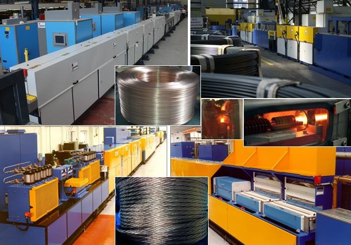
There are noticeable benefits of compact induction systems compared to fluidized beds, infrared heaters, and gas furnaces, such as quick response and the ability to provide a rapid change in the process operating parameters to accommodate the required temperature of the wire/cable being processed at speeds up to 5 mps. Frequencies that are in the range of 10 to 800 kHz are commonly applied. A dual-frequency concept can be beneficial to enhance electrical efficiency of while heating different diameters/thicknesses or it can be advantageous for through heating of metallic alloys that exhibit low toughness/high brittleness.
According to the dual-frequency concept, a lower frequency is used during the initial heating stage when the steel is magnetic. In the final heating stage, when the steel becomes nonmagnetic with significantly increased current penetration depth δsteel and becomes substantially more ductile, it is beneficial to use a higher frequency.
Case study¹:
As an example, consider the induction heating of a 1/8 inch-diameter (3.2 mm-diameter) steel rod from ambient to 2000°F (1100°C) using both a single 10-kHz frequency and dual 10-kHz/200-kHz frequencies (see Figure 2). When using the single frequency of 10 kHz (Figure 2, left), the rod’s final temperature experiences very little change regardless of the coil power that is increased more than fivefold (from 17 to 90 kW). The only noticeable difference is related to the initial slope of the temperature-time curve, where the steel is ferromagnetic. Upon reaching the Curie point, there is no noticeable temperature rise. This is the result of severe eddy current cancellation making the steel rod transparent (practically speaking) to the electromagnetic field of the induction coil.

In contrast, Figure 2, right, shows that a dual-frequency approach provides a remarkable improvement in the ability to heat the rod above the Curie temperature. A power of 14 kW/10 kHz was used to heat the rod below the Curie point and a power of 19 kW/200 kHz was used above it. The total required power is only 33 kW, compared with 90 kW using just 10 kHz, which was still unable to provide the required temperature rise.
Note: The target temperature of 2000°F (1100°C) is above typical target temperatures when hardening plain carbon or low alloy steels and it is more suitable for hot forming applications. This temperature was selected here to better illustrate a dual-frequency concept and the importance of avoiding eddy current cancellation when choosing operating electrical frequencies. It should be noted though that it is not unusual that the heat treating protocols/recipes for some alloyed steels and stainless steels may require target temperatures of 1900°F to 2100°F (1050°C to 1150°C) range.
In some not too often cases, three frequencies may be used. Lower frequency is applied for preheating inductors, a medium frequency is used for mid-heat inductors, and a high frequency is used for final heat inductors.
Sometimes, it is required that the induction system should be able to heat a variety of sizes using a single frequency. In these cases, in order to provide efficient steel heating, it is necessary to choose a frequency that will guarantee that the “diameter-to-current penetration depth (δsteel)” ratio exceeds 3.6 for any workpiece diameter or heating stage. Thus, it is important to remember that when calculating δsteel, the values of electrical resistivity and relative magnetic permeability of the heated material should correspond to their values at the highest temperature that occurs during the entire heating cycle.
The next installment of this column will review a variety of styles of inductors used in continuous and progressive induction hardening applications.
References
- V.Rudnev, D.Loveless, R.Cook, Handbook of Induction Heating, 2nd Edition, CRC Press, 2017.
- J.Mortimer, V.Rudnev, D.Clowes, B.Shaw, “Intricacies of Induction Heating of Wires, Rods, Ropes, and Cables”, Wire Forming, Winter, 2019, p.46-50
Dr. Valery Rudnev, FASM, IFHTSE Fellow, is the Director of Science & Technology, Inductoheat Inc., and a co-author of Handbook of Induction Heating (2nd ed.), along with Don Loveless and Raymond L. Cook. The Handbook of Induction Heating, 2nd ed., is published by CRC Press. For more information click here.