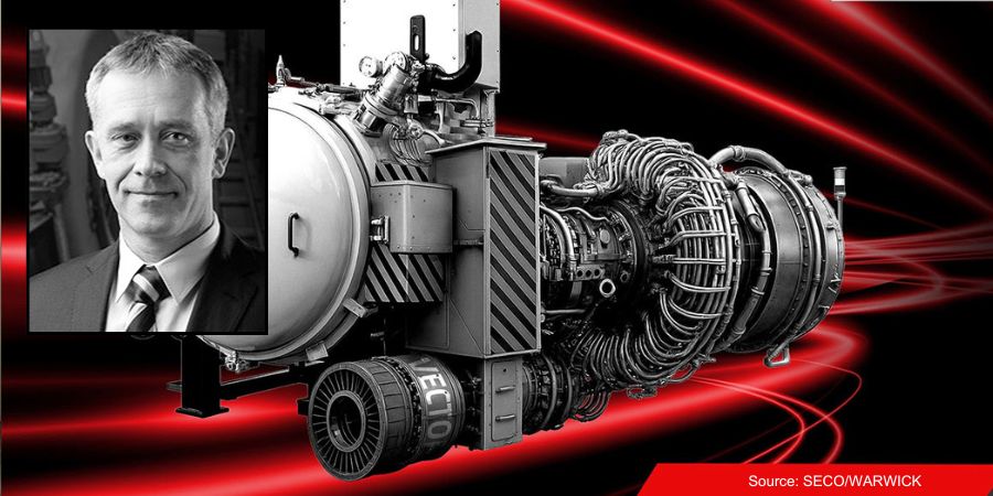
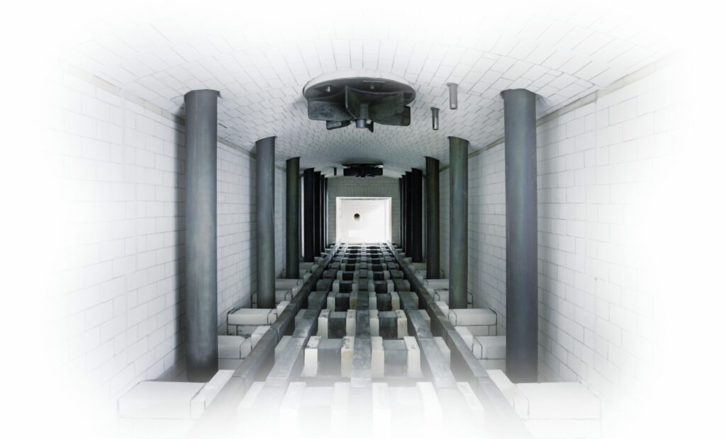
A vacuum furnace was commissioned for the global energy industry. The furnace is equipped with a large working space (900 x 900 x 1200 mm) and a rapid cooling system at pressures up to 6 bar for the production of gas turbine components.
Maciej Korecki Vice President of Vacuum Segment SECO/WARWICK Kamil Siedlecki Sales Manager SECO/WARWICK Source: LinkedIn
“This Partner is responsible for generating about 30% of the world’s electricity today, and their activities play a key role in the energy transition,” said Maciej Korecki, vice president of the Vacuum Segment of the SECO/WARWICK Group, which will provide the furnace.
The furnace is the ninth device delivered to this partner. It provides a high level of vacuum, convective heating up to 850°C, improved efficiency in lower temperature ranges, the capability of using three process gases (argon, nitrogen, hydrogen), precise partial pressure control to minimize alloy losses and ensure process purity, and consistent temperature distribution.
“This furnace is a response to the growing production needs of the client and the requirements related to the processing of a new type of gas turbine component. Our solution will increase process efficiency while maintaining the highest quality and process purity,” says Kamil Siedlecki, sales manager of SECO/WARWICK.
It is predicted that the value of the global gas turbine market for power generation will grow at an average growth rate (CAGR) of 5.7% from 2025–2034. This is driven by the energy transition and demand for efficient, environmentally friendly energy solutions.
Press release is available in its original form here.
This Technical Tuesday installment is part of the Maintenance Message column series. In today’s edition Nate Sroka, quality assurance engineer for Ipsen, provides a complete maintenance guide to rebricking and relining atmospheric furnaces.Keep this one bookmarked for a quick reference to components, the rebricking process, expectations, and project timeline questions!
This informative piece was first released in Heat TreatToday’sAugust 2025 Automotive Heat Treating print edition.
Introduction
The interior brick walls of an atmosphere furnace endure extreme temperatures — sometimes reaching 2200°F — every hour of every day. Over time, the bricks become brittle, crack, and experience thermal expansion, which can open seams in the mortar.
After years of continuous operation, users may notice exterior walls becoming hot enough to melt insulated cables or components attached to the furnace. When bricks start falling out of place or insulation begins to sag, it’s time to shut down the furnace, assess damage, and plan for repairs. Typically, furnaces operating for five to ten years since installation or their last major overhaul require rebricking or relining.
Understanding the Components: Bricks and Boards
Knowing the key components used in the rebricking and relining process prepares you for discussions about repairs.
Insulated Fire Bricks (IFB) come in various temperature ratings. A 2300°F brick is less efficient and durable under extreme heat than a 2600°F brick but is often more cost-effective. High-rated bricks typically line the interior, while lower-rated bricks provide an additional insulation layer.
Insulating boards made from calcium silicate form the thermal barrier between the heating chamber and external components. They can withstand temperatures from 1000°F to 1800°F and are commonly used in lower-temperature furnaces.
Mineral wool is a fibrous insulating material used to fill gaps around furnace entry points and seams. Made from volcanic rock, ceramic, or slag, it allows for expansion and contraction due to temperature changes.
One key thing to know about atmosphere furnaces is that they are almost always “on.” In a vacuum furnace, recipes use electric elements that shut off after every cycle, and quenching often happens within the same chamber. However, in an atmosphere furnace, turning off the burners and then restarting the furnace from room temperature the next day is much less energy efficient than running the burners and holding a consistent temperature, even when the furnace is empty. Parts from an atmosphere furnace are typically quenched in an oil or salt bath, separate from the heating chamber.
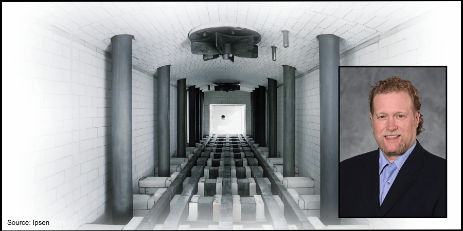
Figure 1. Debris from a damaged atmosphere furnace that collapsed on a hearth Source: Ipsen
Starting the Rebricking Process: What You Need to Know
Prepare for a Quote
First, review the pre-quote checklist to make sure you have the right information to get an accurate quote.
Pre-Quote Checklist: Important information to have on hand when getting a quote for rebricking or relining your atmosphere furnace
Furnace model number and serial number
Heating chamber dimensions (w/d/h)
Archway dimensions from base to top
Door dimensions and condition
Drawings or engineering plans outlining any aftermarket modifications
Typical operating temperatures
Any additional materials installed to prevent heat penetration
Photos from as many angles of the furnace as possible
A list of any consumable or heavy-wear components that also need to be replaced
Build a Timeline
Start collecting quotes at least a year in advance and place a purchase order no less than six months before the planned shutdown.
Consider Scheduling Factors
Many furnace operators are looking to have work like this completed during a summer or winter holiday shutdown period. Advanced planning improves scheduling flexibility.
Site Preparations
Before the service team arrives, ensure the workspace is ready:
Clear space for staging new materials and removing old bricks.
Provide access to a forklift, a durable waste collection container, a dumpster, and other required tools and resources.
Confirm power connections near the site for welding and other power tools.
Review lockout/tagout procedures with maintenance and operations teams.
Determine the required furnace cool-down time before disassembly and plan furnace shutdown accordingly.
Identify and disconnect any electrical, process gas, or water-cooling lines as outlined prior to service.
Rebricking Day: What You Should Expect
During disassembly, consider performing additional maintenance, such as:
Inspecting and rotating or replacing burner tubes
Inspecting and replacing pusher chains and skid hearth section
Checking doors, door hoods, and fan bungs
Conducting leak tests and changing the quench oil
Coordinate these tasks with the service team to avoid disruptions. The rebricking process spans several days, allowing time for concurrent inspections and repairs.
Final Inspection and Testing
Upon project completion:
Figure 2. A newly installed furnace, bricks properly installed, before furnace ignition Source: Ipsen
Inspect the furnace with the installation team to ensure all work aligns with project specifications.
Document any changes as a reference for future maintenance.
Perform a “dry out” procedure and clean the quench tank before refilling the tank. See “Example Dry Out Procedure” break-out box.
Run the furnace without parts to test for temperature uniformity.
Carburizing furnaces may need extra burn-in time to “season” the bricks:
Fresh bricks absorb free carbon until fully saturated.
When bricks are properly saturated, furnace atmospheres stabilize.
Time of burn-in is dependent on the percentage of carbon-level the system needs to achieve.
Identify potential hot or cold spots that may require further insulation adjustments.
Post-Installation Best Practices
A rebrick or reline of a furnace is a significant investment. To get the most from your furnace, make the time to take a proactive approach:
Establish a daily maintenance inspection for the first week, followed by weekly checks for the first month.
Resume regular maintenance schedules if no issues arise.
Schedule independent inspections with a field service engineer at three, five, seven, and nine years to proactively assess furnace condition and secure preferred maintenance dates.
By following these steps, atmosphere furnace operators can maximize uptime, streamline service quoting, optimize downtime usage, and ensure efficient future rebuilds.
This article was originally published on ipsenusa.com.
About The Author:
Nate Sroka Quality Assurance Engineer Ipsen
Nate Sroka has been with Ipsen since March 2014. He holds a bachelor’s degree in mechanical engineering and a master’s degree in engineering and industrial management from Northern Illinois University. Nate oversees the Quality/Documentation/Warranty (QDW) department, ensuring that Ipsen maintains ISO 9001 and ISO/IEC 17025 standards. He is also responsible for documentation related to installation and operations manuals, regulatory certificates, and managing warranty programs.
For more information: Contact Nate Sroka at nate.sroka@ipsenusa.com.
Heat Treat Today offices will be closed today in honor of Labor Day and will reopen on Tuesday, September 2. We hope you enjoy the long weekend with friends and family!
IperionX Limited will receive $12.5 million from the U.S. Department of Defense (DoD) to accelerate the scale-up of a resilient, low-cost, and fully-integrated U.S. mineral-to-metal titanium supply chain. The project will include scaling up to over 1,000 metric tons per year at the Virgnia Titanium Manufacturing Campus.
The $12.5 million will be applied to purchase orders for long-lead, major capital equipment required for the scale-up. Major incremental capacity categories include titanium deoxygenation, sintering and powder metallurgy consolidation systems; near-net-shape component manufacturing and ancillary infrastructure upgrades.
Anastasios (Taso) Arima CEO IperionX Source: IperionX
“This new U.S. Government obligation allows IperionX to move immediately to secure long-lead capital equipment and lock in manufacturing slots with key suppliers. It accelerates our imminent Virginia expansion beyond 1,000 tpa of high-performance titanium manufactured products, and advances a fully integrated, low-cost and traceable American titanium supply chain for defense and commercial customers. This commitment from the DoD is a strong endorsement of our technology, our team, and our mission to reshore a resilient titanium production supply chain in the United States,” said Anastasios (Taso) Arima, IperionXCEO.
In response to the strategic need for increased production capacity of domestic primary titanium metal and manufactured titanium metal components, the project scope under the Industrial Base Analysis and Sustainment (IBAS) program has been revised to prioritize accelerated expansion of IperionX’s titanium metal and manufacturing production capacity at IperionX’s Virginia Titanium Manufacturing Campus.
This project is part of a previously announced $47.1 million award to strengthen the U.S. Defense Industrial Base by accelerating the scale-up of a resilient, low-cost, and fully-integrated U.S. mineral-to-metal titanium supply chain.
Press release is available in its original form here.
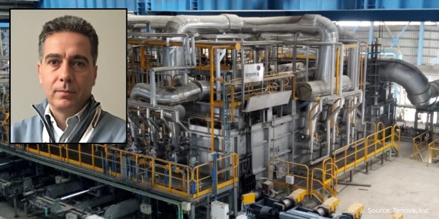
Vinton Steel, headquartered in Vinton, Texas, has commissioned a new walking hearth reheating furnace. The furnace will be engineered for high-carbon steel billets used to manufacture large-diameter grinding media, a high demand product for the mining sector.
This addition is intended to operate alongside a new initiative to increase Vinton Steel’s rebar production capacity up to 400,000 tons per year. The initiative is called Green CityMill™ Flex, which represents an efficient and sustainable long products production platform.
Francesco Memoli
President & CEO
Tenova Inc.
“This project is part of the strategic expansion of Kyoei Steel in the vital North American market and a clear demonstration of our long-term commitment to the State of Texas,” said Masahiro Kitada, board director & executive managing officer for Kyoei Steel Group and chairman of Vinton Steel. “With this additional project, we contribute even more to the continued growth of the El Paso region.”
Francesco Memoli, president and CEO of Tenova Inc., added: “We are honored that Vinton Steel continues to place its trust in Tenova’s technologies. This new reheating furnace will be the most advanced of its kind, equipped with sophisticated control systems and our proprietary low-NOx burners.”
The reheating furnace is scheduled for commissioning in parallel with the Green CityMill™ Flex startup in the first half of 2027.
Press release is available in its original form here.
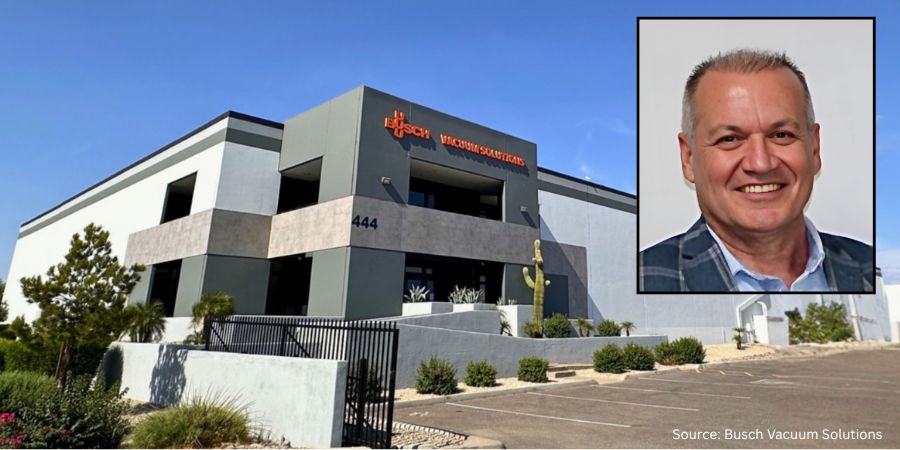
Busch Vacuum Solutions, part of the Busch Group, a global company in vacuum and overpressure technology, has announced the development of its newest U.S. facility. As a key regional hub, the facility will specialize in the repair, service, and overhaul of vacuum pumps, vacuum systems, and overpressure equipment including turbo molecular pumps, leak detectors, valves, and accessories. The almost 60,000-square-foot facility will be located in Tempe, Arizona.
Turgay Ozan President & CEO Busch Group USA
The state-of-the-art facility is scheduled to open in October 2025. This expanded capability brings greater flexibility, technical expertise, and responsiveness to customers across the semiconductor, industrial, medical, and environmental sectors. The Tempe Service Center will provide faster turnaround times, expert support, and more efficient service delivery tailored to the unique operational needs of those across the U.S.
“This investment represents more than just added square footage. It’s about proximity, partnership, and performance. With the launch of our Tempe location, we’re better positioned to deliver unmatched value…on advanced vacuum technologies in high-performance environments,” said Turgay Ozan, president & CEO of Busch GroupUSA.
Corey Woods Mayor Tempe, Arizona
The mayor of Tempe, Corey Woods, commented, “We’re excited to welcome Busch Vacuum Solutions…Their decision to invest here speaks to the strength of Arizona’s semiconductor ecosystem, diversity of thriving industries located here, and the spirit of innovation that defines our community. The new Tempe Service Center will create skilled employment opportunities, strengthen business partnerships, and keep Tempe at the forefront of high-tech growth and excellence.”
In addition to semiconductor and industrial markets, Busch’s vacuum technology supports automotive, food and beverage, packaging, metallurgy, pharmaceuticals, plastics, and large-scale distribution. These capabilities enable more localized production and increase operational resilience across essential supply chains.
Press release is available in its original form here.
The Heat Treat Doctor® has returned to offer sage advice to Heat Treat Today readers and to answer your questions about heat treating, brazing, sintering, and other types of thermal treatments as well as questions on metallurgy, equipment, and process-related issues.
This informative piece was first released in Heat Treat Today’sAugust 2025 Automotive Heat Treating print edition.
Quench cracking during heat treatment can turn expensive components into scrap metal in seconds. In today’s Technical Tuesday article, Dan Herring (The Heat Treat Doctor®) explores more about the underlying mechanisms and proper preventative measures to save you time, money, and ensure reliable part performance.
As a young heat treater, I learned first-hand about quench cracking while running various dies for our tool and die shop — and succeeded in cracking all of them! I have never forgotten the foreman’s (rather animated) critique of my heat treating abilities. Quench cracking can be a significant problem for heat treaters, its potential consequences ranging from costly rework to premature failure in the field. Let’s learn more.
We must not only understand the mechanisms involved but also take proactive steps to avoid it. This includes careful consideration of such items as:
Material (e.g., chemistry, hardenability, form, mill processing)
Component part design (e.g., sharp radii, thin and thick sections next to one another)
Manufacturing processing steps (e.g., the effect of stress relief after rough machining)
Part loading (e.g., part orientation in relation to the quench, fixturing, total load weight)
Equipment choice (i.e., limitations and capabilities)
Quench medium (e.g., type, agitation, flow characteristics, temperature, temperature rise)
Process parameters (e.g., ramp rates, atmospheres, vacuum levels)
The Heat Treatment Challenge
Quench cracking primarily occurs during the hardening process, typically when materials are rapidly cooled via quenching. Since the cooling process introduces internal stresses within the material, it can result in crack formation. These stresses are a result of the rapid transformation of the material’s microstructure, most notably when transforming to martensite, a very hard, brittle structure.
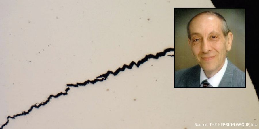
Figure 1. Quench crack in a 4140 axle shaft
Mechanisms Involved
Failure mechanisms related to quench cracking include the following seven factors.
Material Imperfections
As material is heated, thermally induced stresses can cause existing surface or subsurface defects, such as inclusions, laps, and seams. These defects act as stress risers to open and propagate into cracks. Once a defect reaches “critical flaw size” — the smallest flaw that can lead to failure under expected operational stress levels — crack propagation will begin and lead to part failure.
Rapid or uneven heating only exacerbates this issue, especially when a material undergoes phase transformations that introduce volumetric changes.
Stress Risers
Sharp corners, steep edges around holes, and even grooves in parts create stress concentration points where quench cracking is most likely to occur. These features also result in localized heating and cooling, causing differential stresses that can initiate cracks.
The sharp edges of a part, for instance, cool much faster than the rest of the material, leading to a high risk of cracking.
Proper design modifications, such as adding radii to sharp corners, can reduce the likelihood of stress concentrations.
Rapid Cooling and Phase Transformation
The transformation from austenite to martensite during quenching is a key contributor to internal stresses. The rate at which the material cools can greatly influence these stresses. If cooling is too rapid or if tempering is delayed, the material can become overly brittle, leading to quench cracking.
Improper Heating and Overheating
Overheating during the austenitizing process can lead to coarse-grained structures that are more prone to quench cracking. Coarse grains increase the depth of hardening but reduce the material’s resistance to cracking. It is critical to avoid temperature overshoot, high ramp rates, and excessively long dwell times when heating.
Inadequate Quenching Methods
The choice of quench medium (brine, water, oil, polymer, high pressure gas, etc.) can also contribute to quench cracking. Overly aggressive quenchants may create excessive thermal stresses.
Improper Fixturing
The way parts are positioned during quenching can create problems. If parts are bunched together in a basket, uneven cooling rates will occur, with parts on the edges cooling faster than those in the center. This can lead to differential stresses and increase the risk of cracking.
Delays Between Quenching and Tempering
Quenching produces high residual stresses in the material, and if parts are not tempered soon after quenching, these stresses can lead to cracking. For materials with high hardenability, such as 4340 steel, immediate tempering (usually within 15 minutes of quenching) is critical to prevent in-service failure.
Understanding Fracture Mechanics
Contact us with your Reader Feedback!
Understanding these mechanisms is critically important. A material’s fracture toughness, which is the ability to resist crack growth, is defined by the stress intensity factor (KIC). This value varies based on the material’s properties and the size and geometry of the crack. The important point to remember is that when the applied stress reaches a critical threshold, cracks begin to propagate (literally at the speed of sound), leading to catastrophic failure.
Digging a bit deeper, there are three primary modes of fracture:
Tensile (Mode I): Fracture caused by tensile stress at the crack tip.
Sliding (Mode II): Fracture caused by shear stress that causes the two sides of the crack to slide.
Tearing (Mode III): Fracture caused by shear forces in a direction perpendicular to the crack plane.
Preventive Measures
Several strategies can be employed to minimize the risk of quench cracking during heat treatment. They broadly fall into the following categories.
Material Selection
Choosing the right material for the job is essential. Many designers select materials with high hardenability, forgetting that they can be prone to cracking. Additionally, one should take special care with materials that have high carbon content or are heavily alloyed.
Design Considerations
Ensure that part designs minimize stress risers. Avoid sharp corners and incorporate radii where necessary. Proper design can reduce the likelihood of cracks forming at critical locations.
Improved Manufacturing Practices
Proper stock removal during machining and addressing surface imperfections before heat treatment can prevent the initiation of cracks. Machining should aim to eliminate any seams or inclusions that might act as nucleation sites for cracks. Stress relief after rough machining is almost always a good idea.
Control of Heat Treatment Parameters
Maintain tight control over the heating and quenching processes to ensure uniformity. Avoid overheating and try to ensure that the part enters the quench medium in the best possible orientation to reduce the likelihood of creating differential cooling rates.
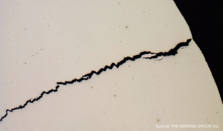
Figure 2. Quench crack due to a combination of rapid heating, overheating and improper
polymer quench medium concentration in a motor shaft (50x, as polished)
Quenching Media
Select the appropriate quenching medium based on the material, part geometry, and load. Less aggressive quenchants or minimizing time in the quench should be considered for materials with moderate to high hardenability.
Post-Quench Tempering
Temper parts as soon as practical after quenching to avoid concerns with internal stresses. High-hardness materials should be tempered immediately to prevent quench cracking.
Quench Cracking in Other Materials
Quench cracking is not exclusive to steel. Other materials, such as nickel and cobalt superalloys, can also experience cracking due to similar mechanisms. In these materials, the phenomena are often referred to as “fire cracking,” “strain-age cracking,” or “stress cracking.” As with steel, cracks in these materials are often linked to high residual tensile stresses on the surface and the presence of stress raisers. Strategies, such as shot peening, redesigning part geometries, and improving surface finishes, can help mitigate cracking in superalloys.
Summing Up
Quench cracking represents a significant challenge in heat treatment, but by understanding its underlying mechanisms, heat treaters and engineers can take steps to mitigate the risk. Material selection, part design, proper heat treatment procedures, and timely tempering are all critical factors in preventing quench cracking and ensuring the integrity of components. A proactive approach to addressing flaws and stress concentrators combined with careful attention to detail in every stage of the manufacturing and heat treatment process can greatly reduce the likelihood of failure and contribute to the long-term success of heat treated products.
References
Herring, Daniel H. 2012. “Quench Cracking.” Industrial Heating, April.
Herring, Daniel H. 2015. Atmosphere Heat Treatment, Volume 2. BNP Media.
Johnson, D. D. 2005. “Thermal and Mechanical Behavior of Materials.” University of Illinois.
Klarstrom, Dwaine L. 1996. “Heat Treat Cracking of Superalloys.” Advanced Materials and Processes, April.
Krauss, George. 2005. Steels: Processing, Structure and Performance. ASM International.
About the Author
Dan Herring “The Heat Treat Doctor” The HERRING GROUP, Inc.
Dan Herring has been in the industry for over 50 years and has gained vast experience in fields that include materials science, engineering, metallurgy, new product research, and many other areas. He is the author of six books and over 700 technical articles.
ATI Inc. and The Boeing Company have expanded their agreement for high-performance titanium materials for aerospace. ATI will supply high-performance titanium materials, including long products — such as ingots, billets, rectangles, and bars — and flat-rolled products, including plate, sheet, and coil.
Kimberly Fields President & CEO ATI Inc.
ATI‘s extension and expansion of its long-term titanium products agreement will support Boeing‘s narrowbody and widebody airplane operations.
“We’re proud to expand our decades-long partnership with Boeing,” said Kimberly Fields, president and CEO of ATI. “This agreement reaffirms ATI’s leadership in titanium at a time of accelerating aerospace production and growing demand for differentiated materials. It also deepens our position in high-strength titanium alloys and sheet products…It includes titanium alloy sheet from our new Pageland, South Carolina, facility and draws on the strengths of both our Specialty Materials and Specialty Rolled Products businesses.”
Specialty Rolled Products Source: ATI Inc
ATI is a producer of high-performance materials and solutions for the aerospace and defense markets, and critical applications in electronics, medical and specialty energy, and a Nadcap certified heat treater. They provide alloys in a full range of mill products, forgings, titanium castings, and machined components, designed for the high performance requirements such as for aerospace and defense, oil and gas/chemical process industry, electrical energy, and medical.
Press release is available in its original form here.
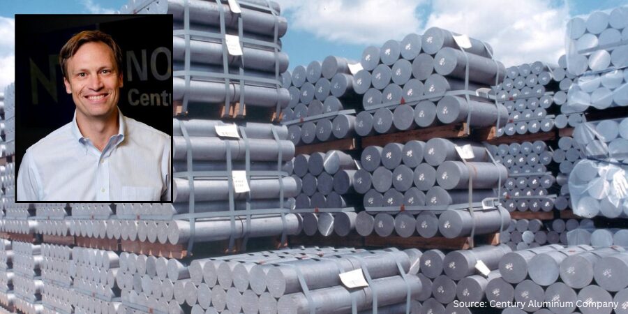
Century Aluminum Company has announced plans to restart over 50,000 mt of idled production at its Mt. Holly, SC smelter. Part of a $50 million investment, the effort will create over 100 jobs and boost U.S. domestic aluminum production by almost 10%.
Jesse Gary CEO Century Aluminum
The restart will enable the plant to achieve full production (up from current 75%) by June 30, 2026. The restart follows President Donald’s Trump’s tariffs for primary aluminum, most recently increasing the tariffs to 50% on aluminum imports without exceptions or exemptions.
“Our team stands ready to continue leading the resurgence of domestic primary aluminum, starting with bringing our Mt. Holly smelter back to full production.” said CEO of Century Aluminum Company, Jesse Gary.
The restart was made possible with the help of South Carolina Public Service Authority (Santee Cooper), Mt. Holly’s power supplier. The parties extended the current contract through 2031 to purchase the additional power necessary for the restart. The final details of the restart will be subject to a definitive agreement with Santee Cooper, along with confirmation of economic incentives provided by Berkeley County and the state of South Carolina.
Century Aluminum is an integrated producer of bauxite, alumina, and primary aluminum products. At full capacity, Mt. Holly smelter has an economic impact of over $890 million annually in the state of South Carolina. Century is the largest producer of primary aluminum in the United States, and operates production facilities in Iceland, the Netherlands, and Jamaica.
Press release is available in its original form here.
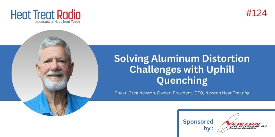
What do Mars rovers, sniper pods, and rotor grips have in common? Uphill quenching — a thermal-mechanical technique that uses liquid nitrogen and high-velocity steam to dramatically reduce stress and distortion.
In today’s episode of Heat TreatRadio,Greg Newton, Newton Heat Treating CEO, joins host Doug Glenn to take a dive deep into this little-known but highly effective process for controlling residual stress in aluminum alloys. Guest John Avalos, Newton’s quality engineer and IT/Digital Transformation Manager, joins the conversation.
Get the full picture of how this thermal-mechanical method improves machinability, enhances precision, and extends component life, especially in aerospace and optical applications.
Below, you can watch the video, listen to the podcast by clicking on the audio play button, or read an edited transcript.
The following transcript has been edited for your reading enjoyment.
Introduction (2:20)
Before we even start talking about the process, let’s talk about your qualifications and experience. How did you get in heat treating and aluminum heat treating?
Greg Newton: In 1968, my father opened up a heat treating facility in the city of industry. From age 13 on, I had a summer job and weekend job. It’s part of my blood. In the early ‘70s, we were the first heat treater to purchase an X-ray diffraction machine, which is a non-destructive way of checking for residual stresses beneath the surface of aluminum alloy and different alloys; we concentrated on aluminum. It’s an old analog Rigaku machine; it’s still running. It gives me great data, so why change it out for a half-million-dollar new machine? That’s how we got started.
There was a pilot project with Northrop Grumman for controlling residual stresses, taking glycol out of the laboratory and putting it in production. Now, one thing I didn’t like about that project was that we gave all the data to Northrop and then they wrote a spec and gave it to the world. I didn’t feel we got our fair payback for it.
When theM1 tank optics came along and they knew we had X-ray diffraction on premises, they wanted to take something basically out of the laboratories. The patent names it “thermal mechanical uphill quenching,” which describes the process perfectly. We use it because of the residual stresses created during the quench cycle. When you go from roughly 1000°F down to room temperature rapidly, that’s what sets up your mechanical properties in aluminum.
What Is Uphill Quenching (5:02)
Doug Glenn: Let’s take a 30,000-foot view for someone who has no concept of what an aluminum alloy is. What is uphill quenching?
Greg Newton: It’s the inverse process of the quenching cycle in the solution heat treat cycle. You’re going roughly from 1000°F to room temperature, hot to cold. A part can’t cool instantly. What happens? The outside cools first. It shrinks, and you get a compressive shell. By the laws of thermodynamics, I have an equal and opposite action happening in the core of that part. So, it develops tensile stresses to hold up that compressive shell. They’re in equilibrium when I’m done with the part and I send it back to the machine shop.
Then, they’re going to remove material from one side; they’re going to gun drill it. That’s when challenges arise, because at the point of after-quench, we have the compressive shell and the tensile stresses in the core. They are in equilibrium. When I remove material away, that compressive shell moves, and that’s where aluminum becomes very difficult to machine.
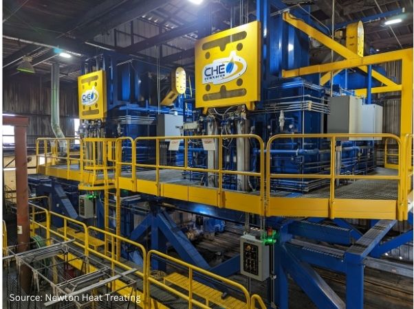
Newton Heat Treating’s thermal processing equipment
Source: Newton Heat Treating
Doug Glenn: Does uphill quenching solve this problem?
Greg Newton: It solves the problem, for all parts, all shapes, all sizes. Parts that don’t lend themselves to flip flopping, which never solves the problem. You might machine away some compressive shell, rejig the part, flip it over, remove a little of the compression on the other side, but you still have those tensiles. The tensiles are the bad guys. That’s what’s causing a failure in use and propagating cracks.
Doug Glenn: Tensile stresses are the ones pushing out, whereas the compressive strengths are the ones that are pulling in.
Greg Newton: And a compressor shell can actually be advantageous for certain types of fatigue, like creep.
Doug Glenn: Is uphill quenching predominantly done on aluminum or exclusively done on aluminum?
Greg Newton: It is predominantly done on aluminum. We’ve done a little bit on titanium. It had fair results with it. Alcoa developed uphill quenching in the late ‘50s. That’s how old this technology; it’s nothing new. Back then, though, engineers used to design things 2.5 times as robust as they needed to be, just because we didn’t know how much residual stresses were inherent in the manufacturing of these parts. But now, with trying to get aircraft, car, and all other types of components to be as light and as thin as possible, this process comes into play. It has finally come of age.
Neutralizing Stresses with Uphill Quenching (7:50)
Doug Glenn: So you have the compressive and tensile stresses, and uphill quenching basically is helping to neutralize or to balance those so that when you go to machining and you’re doing some machining, you’re not going to get what you would anticipate with a distortion or something of that sort.
Greg Newton: Well, again, we go back to the original patent name that describes the process perfectly. Thermal, mechanical, uphill grade. We’re not stretching it with a hydraulic press to 1.5–3% to dislocate the lattices. We’re using a thermal gradient. That’s our energy. That’s our machine.
It’sa little hard to wrap your head around. We’re going to compress and get the dislocation that way. Well, what put those stresses in was that thermal gradient of the quench roughly going from 1000°F to room temperature. How can we reverse that? Aluminum, unlike steels, is almost annealed soft in an as-quenched (AQ) condition.
So that is the optimum time, as the original patent tells you. There are so many misconceptions out there. When you do it in a hardened condition, you’ve lined up everything against yourself. You’ve increased yield strength. You want to do it when the material is as soft as possible. For aluminum, you want to either do it immediately after quench, within an hour, or retard the natural aging by putting it in a sub-zero freezer.
Doug Glenn: The uphill quenching is neutralizing those stresses, so there could be further processing without as much “fear.”
Greg Newton: That’s correct. We’re going to go from -320°F and heat it up with a high-velocity steam blast, back up past room temperature.
Doug Glenn: We’ll get to the actual process, I just wanted to make sure we’re understanding why we’re doing it.
Greg Newton: The machinability of aluminum are close-tolerance parts: They diamond hone our laser optics to a millionth of an inch in aluminum.
Doug Glenn: Wow.
John Avalos: That’s a tight tolerance.
Doug Glenn: Yeah, that’s a tight tolerance. So basically, uphill quenching is just the inverse of the quench.
Greg Newton: That’s all it is.
Doug Glenn: Coming downhill on the quench, then we’re going back uphill. Is this similar to a temper process for a ferrous material?
Greg Newton: We’re not changing any of the mechanical properties. All we’re doing is a realignment of the lattice parameter of the inner crystalline structure.
Doug Glenn: That sounds so different.
Greg Newton: If you picture that compression pushing in and the tensiles pulling out, we’re relaxing them back to a neutral state.
Want to read more about the Newton Heat Treating’s story? Click the image for a full article.
John Avalos: But the main point is that it doesn’t change the temper at all.
Greg Newton: It does not change any of the mechanical properties.
Doug Glenn: Is uphill quenching predominantly or exclusively used in aerospace or are there other markets where you use it as well?
Greg Newton: There are other markets — any close-tolerance parts in aluminum and the alloys. It’s extremely effective on all alloys; 6061 is used in the laser industries or laser optics. We do a lot with the optical industry.
Doug Glenn: So it’s not just aerospace, but a good chunk of it is.
Greg Newton: Nothing on Mars hasn’t come through our hands. I mean, all the gating and sending antennas, all the optical housings, the wheels even were cold stabilized, because they’re trying to make them so light. They’d gun drill them and they would collapse.
Doug Glenn: Did you say “nothing on Mars”?
Greg Newton: All the parts for the Mars rovers have come through our facility.
Actually, our first parts were on Voyager. We’d been looking at this process, and JPL (NASA Jet Propulsion Laboratory) came to us requesting us to try uphill quenching the parts. Dr. Martin Lo from JPL hand-carried these parts over that are still sending data on Voyager that is outside the influence of our sun. Isn’t that incredible?
Doug Glenn: That is incredible. I think it’s just so fascinating what this industry does that people don’t know about.
Getting Technical: The Uphill Quenching Process (12:37)
Doug Glenn: Let’s jump into it and talk technical. What is involved in the uphill quenching process?
Greg Newton: You take these heat treated parts and either perform the uphill quench within an hour or retard the natural agent, that’s key. There are companies that try to uphill quench in a hardened state, and you will get some reduction in stresses, probably more than you will get from any straight thermal stress relief where you’re just lowering the yield strength and popping some of the lattices, but this is nowhere near what you’ll get in an AQ condition.
Doug Glenn: Timeliness is important here. That’s probably the first point.
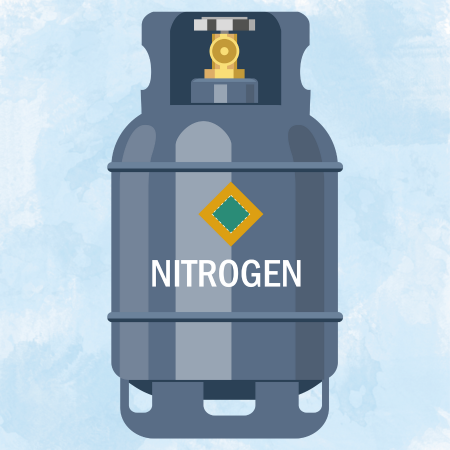
Greg Newton: Very, very important. So some of the equipment you’ll need includes a large door, depending on how big the part is. And you know, we have a 3,000-gallon tank here on premises and we are ready to put a 6,000-gallon one in. Then, all you’re utilizing the LN2 for is its coldness. It’s not like other steel heat treaters and stuff where it’s in the atmosphere. We’re just using it for…
Doug Glenn: Let me interrupt you, Greg. You said an acronym. What is LN2?
Greg Newton: Liquid nitrogen.
Doug Glenn: I assumed, but just want to make sure.
Greg Newton: The boiling point at sea level is -320°F.
Doug Glenn: So you’re taking it down.
Greg Newton: Right. You also need some sort of steam boiler or steam generator; we have both on premises. You may need an accumulator depending on the size of the parts you’re doing, because you’re using the steam, trying to reverse the delta T of the quench as fast as possible.
John Avalos: It’s a rapid process.
Doug Glenn: That’s why steam is very effective at rapidly heating.
Greg Newton: As the original report tells you, the difference is that you’ll get over 80% reduction in stresses utilizing LN2 and steam versus boiling water. The maximum’s around 19%. We’ve done our own testing and have gotten about 20% — so, significantly higher. Doing it in an AQ condition is key. The original report tells you that you get nothing out of doing the process in a hardened condition, which is done by many of my competitors.
We’ll do it any way the client wants it. While we have boiling water capabilities, but I try to talk the client into doing it the preferred way, which is in an AQ condition with LN2 to steam. That’s how you get to your biggest temperature differential, your delta T. You’re trying to match the delta T of the quench of the heat treat quench in reverse. That’s all you’re trying to do.
Doug Glenn: It sounds simple. So far, we have covered needing aluminum as-quenched, as soon as possible. You’re dipping it into LN2 to take it down to -320°F, roughly. Right?
Greg Newton: Depending on the thickness of part, it’s not a soaking cycle like solution heat treating would be, but you do want to make sure that part is completely at that temperature.
Doug Glenn: So you’re taking it down to -320°F, then immediately taking it out, and you’re hitting it with steam for how long, and what’s the criteria?
Greg Newton: It depends on the size, the shape, and the configuration. We have many, many steam fixtures out here that can be slightly modified. If you have a good production run, it’s best to design a fixture specific to that part. Bell Helicopter does this for the rotor grips for the Hueys when they were re-engineered.
Doug Glenn: Are you taking it up then to a specific temperature?
Greg Newton: Yes, we want be above 160°F for casting; 180°F, we prefer, for raw product.
Doug Glenn: Okay, and once it’s back up to that temperature, is the process done?
Greg Newton: You are done. Now there are many specs that repeat the process. I think this is mostly to make up for lack of fixturing, a part-specific fixture, so you can make up with subsequent processing. It does come out of the history of the past of when they really didn’t understand, before the original patent. There used to be tricyclic stress relieving where they would take it from dry ice into boiling water.
One of the advantages of steam, and the reason why you get much better results with steam versus boiling water, is the fact that it’s a higher temperature. It blasts away any ice that’s forming on that part, on the surface of it and it’s a turbulent flow over that part. So it readily transmits that energy quicker.
John Avalos: Can you also talk about the X-ray diffraction and how you use that to measure how effective the process is?
Greg Newton: When we took over this project and we wanted to prove it out, we learned a lot of things. When an engineer patents something, he usually controls everything. And it’s not that they’re wrong, it’s that they are .000001% right. In the real world, it makes no difference. So, you tend to throw those things away because they have no real relevance here on earth or in space.
So,we stumbled upon some other things that were advantageous to buy X-ray diffraction.
The standard operation involved first, getting the part, heat treating it, and then directly after quench, and take a reading because we know after a solution heat treated, we have that perfect setup between the compressive shell and the tensiles and the core. They’re going to be equal. Or close to it.
The thicker the section of the part, the more stresses, because it takes longer to cool. When you get into parts with two-inch cross sections and quarter-inch webbing, that’s when you get a lot of oil canning and all hell breaks loose. We can solve that.
I remember there was a bot part we had for the 767 or 757. It was the pilot’s window, and they were failing in service. The bot had a whole shift Boeing was paying to re-machine all out-of-tolerance parts on the shelf, until they finally they were over-machined and had to be thrown away. We had a hard time. I did parts for nothing to prove it to them, and they adopted it. But then the union fought them, and now that division is closed.
You have to evolve or else you will go the way of the dinosaurs.
Doug Glenn: You can’t fight with science. Ultimately you can’t fight with the truth of metallurgy.
I think we have the basic process down; it doesn’t sound that complicated. It’s a reverse of the quench process, essentially.
“Aluminum alloy 6061 is a forgiving alloy…It lends itself to uphill quenching because of its lower yield than the 7,000 series. We also do work in the 7,000 series.” Source: Theworldmaterial.com
Greg Newton: Attention must be paid to the details, though.
Doug Glenn: Yes, exactly. I have talked with a couple of other people about this process, and I’ve been told that the aluminum alloy is somewhat important in the process depending on what alloy you have. Is that the case?
Greg Newton: Aluminum alloy 6061 is a forgiving alloy, and most of the optics we do are some form of that. It’s a forgiving alloy in many, many ways. It lends itself to uphill quenching because of its lower yield than the 7000 series. We also do work in the 7000 series. It takes a little better steam fixture, perhaps a little more attention to detail. Rough machining comes into play, regarding how much rough machining is done prior to the final solution heat treat and the uphill quench.
John Avalos: There are lots of factors.
Greg Newton: We like to be involved in the beginning, not as an after fact. The best successes we’ve had is when the company knows it’s going to be a problem part, so they get us involved in the beginning. Then, we set it up right and everything goes smoothly, instead of after.
Doug Glenn: You had mentioned the X-ray diffraction and the testing of it. Is there anything more we want to say on that?
Greg Newton: After the solution heat treat, I’m going to get that perfect ratio of my compressive shell and the tensiles. After the uphill quench, we’ll measure again, and then once after aging, because aging can have a slight effect on your stress levels.
That will give us an internal baseline, and we do it for all clients on all first articles. I encourage clients to pay for it, but to a lot of machinists, it’s just an extra cost. But should they ever have a problem in the future? The proof has always been in the pudding. I send it back to them because I can’t tell you how many skeptics we’ve had that call me back and say, “dang, it really worked.” And then they think it’s that magic. Some of the failures that have come from the successes and thinking, “Now I can make up the lost time. I’m going to make twice the cuts, twice as deep, twice as fast.” Then you induce stresses by machining parts.
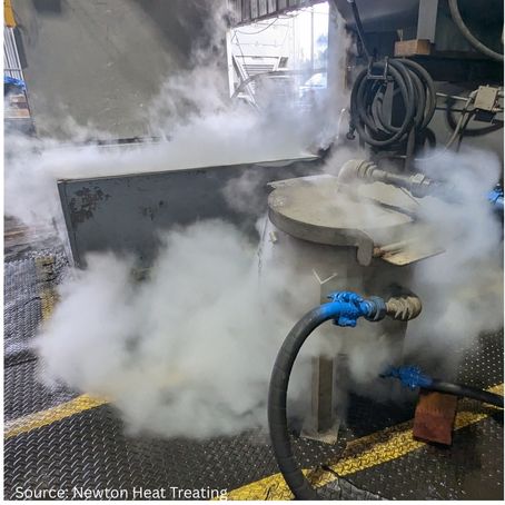
Newton Heat Treating’s equipment for cold stabilization Source: Newton Heat Treating
Doug Glenn: You mentioned that when the engineer initially does the patent, they control everything; they put a lot of standards in there. It sounds to me that in your practical application of this process, you found out which one of those instructions are important, and which ones are maybe not as important.
Greg Newton: We have completely refined the process.
Doug Glenn: Now you know you don’t need to waste time on item X because it really doesn’t matter so much. The correlation for success may be more tied with another item.
Greg Newton: The boiling water aspect becomes so appealing to my competition because you don’t need to use your brain to design steam fixtures and other processes. We have designed many steam fixtures over the years, and they’re semi generic. We can change the inserts for cylindrical parts. We have found it’s very advantageous to steam inside and out, simultaneously. When it says high-pressure steam, I have engineers up with their cameras and I say, “No, no, back away about 30 feet.”
Doug Glenn: Step back from the part. That sounds interesting. The design of the fixtures for the impingement of the steam sounds very similar to me to something we’ve talked to Joe Powell of Akron Steel about. He talks about that high-intensity quench, not uphill quenching, but downhill quenching in this case, where it’s really super critical that you quickly and uniformly cool the entire outer shell at the same time.
It sounds like these fixtures you’re talking about are somewhat along that same line that they need to be hitting the part at the right place, right time, right volume.
John Avalos: They represent the configuration of the part as close as we can anyways, so that we get a nice even steam blast.
Greg Newton: We’ll tend to concentrate steam in thicker areas, back off on thinner areas.
Challenges in Uphill Quenching (25:00)
Doug Glenn: What are the biggest challenges that you face when performing uphill quenching?
Greg Newton: Overcoming the misconceptions of when and how to do it can be challenging as there are so much different variables. We have capacity for boiling water and steam, but we prefer to do the best method possible, and give my clients the best, because the price is the same. I’d rather have a happy client. Then, I think, boiling water sometimes gives it a bad name when it doesn’t work. They often throw out the entire system, the baby with the bath water.
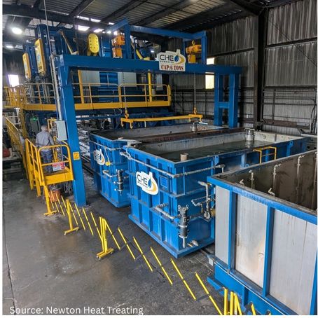
Cyclic thermal shock process Source: Newton Heat Treating
Doug Glenn: In the actual process itself, fixturing can be an issue, placement and configuration of the steam is an issue. I’m guessing part configuration can be challenging, the thick to thin cross-section. What are some of the difficult aspects of uphill quenching or difficult parts.
Greg Newton: One day, Lockheed calls me, and they had a sniper pod for the F16. They tread machined this 1,600-pound hand forging three times and were trying to go to a one piece, monolithic part. They had one more shot until they were going to lose the contract.
So, Don of Lockheed came to me asking if we could do it. They wanted to send me 1,600-pound hand forging and I said, “No, no, you need to rough machine this thing.” I asked how much the part weighed when they were done — “168 pounds.” That’s crazy!
I told them they needed to rough machine the part and then send to me. So, they rough machined it, and I get a part that is 1,200 pounds, but it was 6061. I told them we’ll give it our best shot. We did do multiple stabilizations on that part — I think we stabilized it three times, but it worked.
He was worried about getting this big hand forging back on the machine, because it did move a lot during uphill quenching. We did, in between post-heat treat, straighten it, uphill quench it, then straighten it; each run time it moved less, and, you know, you’re inducing stresses by straightening through the process as well. The third time, we uphill quenched it, checked if we needed to straighten it, and we didn’t. We shipped it, and they got through this. We saw another two or three more.
The challenge is what they think the process will do and what it’s capable of. I don’t think that would’ve worked for the 7000 series. You really want to get it within 150 thousandth to 100 thousands of control, because of the dispersoids they put in the super alloys, making it tougher to uphill clench.
Doug Glenn: What is your most interesting part that you have uphill quenched?
Greg Newton: The rotor grips for the old Hueys. When they re-engineered them and doubled the horsepower, they went from the two blades that you see on the mash that they could hear from 30 to 40 miles away. They increased the horsepower of the engines and went to four composite blades, but the rotor grip itself that they wrapped the carbon fibers around was a 2014 die forging.
But they had machining problems. They would make one pass over it and it would curl up about three quarters of an inch. So, Gene Williams came down from Bell Helicopter and spent a week with me. Bell doesn’t like anybody else’s data; they want to create their own data. So, he was out there with his camera, measuring and doing everything for a week. We got through the machining and they’re dead flat. Now, when I get rid of the stresses, I get rid of all the stresses: the compressive shell and the tensiles. So, they went back to these rotor grips and peened them, glass beaded them. This gave it a nice, even compressed shell without the negative effect of the tensiles in the core.
Now they are getting 8 to 10 times the life expectancy out of these parts, which makes sense on a fatigue curve, because you don’t know where you’re starting on that fatigue curve. Most of the curves go “whoop” [Editor’s Note: Greg demonstrates the exponential swoop of the graphic arc.], and you know you’re in that quarter and then you’re done. They store parts at 50% of their intended life for when they can’t get new parts and pray they get the new ones.
Weget the problem parts, and that usually gets my foot in the door.
Doug Glenn: You mentioned earlier that if a company is developing a part or if they’re having an issue, it’s better for the client and for you guys that the sooner they talk to you the better. Most people don’t think the commercial heat treater or the processor can be that helpful, but with guys like you who have an expertise in the area, it’s probably well worth having an early phone call.
Greg Newton: No heat treater really loves to see final finished parts. It’s a violent process. We would rather have a little beat on that.
Ideal Parts and Benefits (30:45)
Doug Glenn: What type of parts should uphill quenching be performed? Can you give us a quick overview of the types of parts that you’ve uphill quenched?
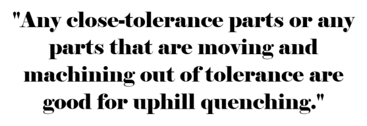
Greg Newton: Any close-tolerance parts or any parts that are moving and machining out of tolerance are good for uphill quenching.
Doug Glenn: What benefit does uphill quenching have over similar or competitive processes?
Greg Newton: With straight thermal stress relieving, in which you’re just raising the temperature of the part, you have to be careful of losing your temper when doing it. To get a real stress relieve, you need to go up 600-700 degrees, and in doing that, you’re going to blow your temperatures right out in aluminum. So, you tend to use 25 degrees below zero for longer periods of time, and you might lower it. That tends to break the most highly strained lattices because you’ve lowered that yield strength a little bit and they’ll pop. That might be enough to get you through that part, the machining.
Is it going to move later in service? Probably. When heating up and cooling it down, especially in space; when you have an unstable part in space and it turns towards the sun gets 200-300 degrees (turns away from space in the vacuum), now you’re thermo cycling. It is a different type of stress relieving, and it can move those mirrors. Any slight movement in those mirrors, and you’ve lost your integrity.
They can figure out mathematically the coefficient of thermal expansion out in space, but warpage is difficult.
Radius of Industry (32:43)
Doug Glenn: You have an expertise in aluminum. What is the radius out of the city of industry that you’re getting clients from?
Greg Newton: We have received Israeli tank mirrors and German tank mirrors. We get parts shipped from the East Coast daily. Hamilton’s products, they attribute their position with the success of their uphill quenching on almost of all their cylindrical parts. They have a better product than anybody else, and they told me that they attribute much of that success the stability of their, their aluminum.
Doug Glenn: Is there anything that you thought of as we’re talking that you want to add into the conversation?
John Avalos: I’ll add that we’re the leaders in this process. There are a lot of similar processes Greg mentioned with boiling water. What that does is it forms the ice barrier around the part. By using steam blasting and uphill quenching, it removes that barrier — a barrier simply doesn’t form.
Greg Newton: Ice is a great insulator.
Doug Glenn: It reminds me of the vapor barrier when you’re trying to quench. It’s an insulator.
Greg Newton: Regarding the X-ray diffraction, having process control is important. You’re spending 10 times a normal heat treat, you’re throwing money in a problem, and there is nobody else that has any process control. To me, that’s playing Russian roulette with five in the chamber, not one. Your chances of success are slimmer. We want to know when something goes wrong. Why did it go wrong? Without any sort of can imagine, if we threw out EC and Rockwell out of our heat treatment and say, “Look, the charts look good! It must be good,” we’d have airplanes falling out of the sky daily.
Heat Treat Radio episode #124 with host Doug Glenn and guests Greg Newton and John Avalos
You have a very expensive problem. I would like to see a little more process control that everybody’s using. Nadcap is trying to tie that up as we speak.
Doug Glenn: Very good. Well, gentlemen, thank you very much I hope the listeners have enjoyed this as well. I think it’s a very interesting, somewhat unique process, and it’s good to talk with you two guys about it.
Greg Newton: I challenge any machine shop out there to send me their biggest nightmare in aluminum
Doug Glenn: He just threw down the gauntlet: Send him your worst stuff, and he’ll see if he can fix it. Anyhow, thanks, Greg and John, thank you so much. I appreciate you guys.
About the Guest
Greg Newton Owner, President, CEO Newton Heat Treating
Greg Newton is the owner, president, and CEO of Newton Heat Treating. Founded by his father in 1968, Greg became president of Newton Heat Treating in 1995 and has decades of experience leading numerous projects in the heat treating industry. Greg has focused specifically on aluminum alloys — specializing in heat treating, uphill quenching, and other advanced thermal processes.