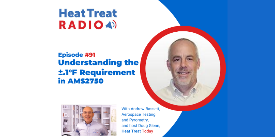
Heat Treat Radio #91: Understanding the ±0.1°F Requirement in AMS2750, with Andrew Bassett
![]()
Where did the ±0.1°F AMS2750 requirement come from and how should heat treaters approach this specification, an important change that entails major buy-in? Andrew Bassett, president and owner of Aerospace Testing and Pyrometry, was at the AMS2750F meeting. He shares the inside scoop on this topic with Heat Treat Today and what he expects for the future of this standard.
Heat Treat Radio podcast host and Heat Treat Today publisher, Doug Glenn, has written a column on the topic, which you can find here; read it to understand some of the background, questions, and concerns that cloud this issue.
Below, you can watch the video, listen to the podcast by clicking on the audio play button, or read an edited transcript.
![]()
![]()
![]()
![]()
![]()
![]()
The following transcript has been edited for your reading enjoyment.
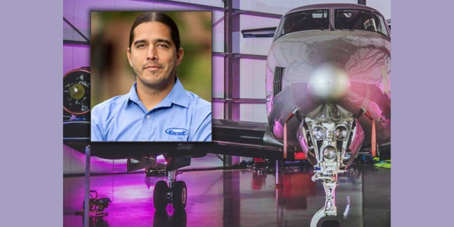
Doug Glenn: Andrew Bassett, president and owner of Aerospace Testing and Pyrometry, Inc., somewhere in eastern Pennsylvania. We don’t know because you’re on the move! What is your new address, now, by the way?

Andrew Bassett: We are in Easton, Pennsylvania at 2020 Dayton Drive.
Doug Glenn: Andrew, we want to talk a bit about this ±0.1°F debate that is going on. It was actually precipitated by the column that I wrote that is in the February issue.
I just wanted to talk about that debate, and I know that you’ve been somewhat involved with it. So, if you don’t mind, could you give our listeners a quick background on what we are talking about, this ±0.1°F debate.
Andrew Bassett: To be honest with you, being part of the AMS2750 sub team, one of the questions came up for us during the Rev F rewrite was this 0.1°F readability — wanting to kind of fix this flaw that’s been in the standard ever since the day that AMS2750 came out. With instrumentation, for instance, you have ±2°F (the equivalent would be 1.1°C). At 1.1°C, the question became, If your instrumentation does not show this 0.1 of a degree readability, how can you show compliance to the standards?
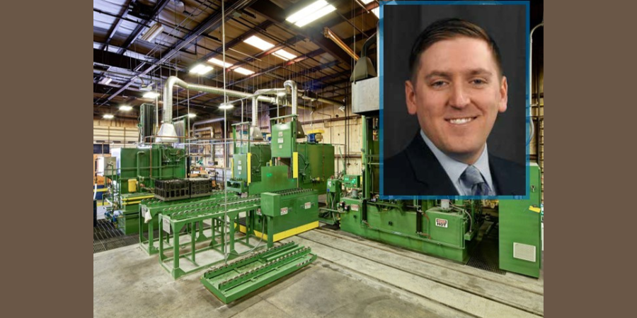
President
Aerospace Testing and Pyrometry
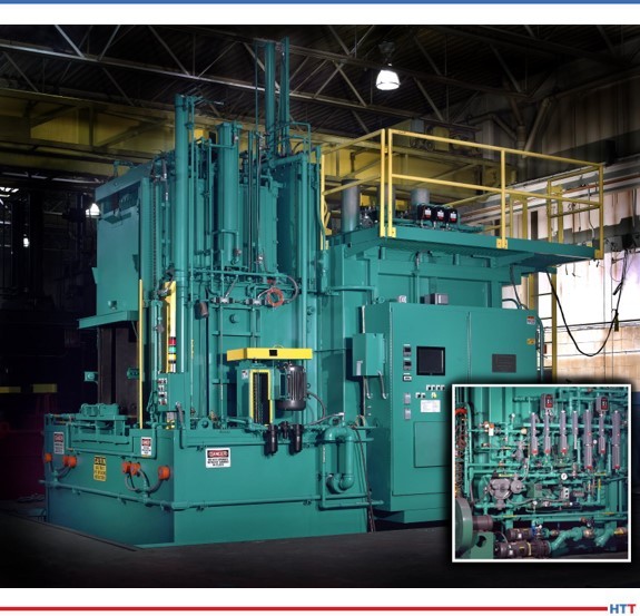
Source: DELTA H
Then, it morphed into other issues that we’ve had in the previous revisions where we talk about precise temperature requirements, like for system accuracy testing: You’re allowed a hard number ±3° per Class 2 furnace or 0.3% of reading, whichever is greater. Now, we have this percentage. With anything over 1000°F, you're going to be able to use the percentage of reading to help bring your test into tolerance. In that example, 1100°F, you’re about 3.3 degrees. If your instrumentation doesn’t show this readability, how are you going to prove compliance?
That’s what it all morphed into. Originally, the first draft that we proposed in AMS2750F was that all instrumentation had to have 0.1°F readability. We got some feedback (I don’t know if I want to say “feedback” or "pitchforks and hammers") that this would be cost-prohibitive; most instrumentation doesn't have that readability, and it would be really costly to go out and try to do this. We understood that. But, at the end of the day, we said: The recording device is your permanent record, and so that’s what we’re going to lean on. But we still had a lot of pushback.
We ended up putting a poll out to AMEC and the heat treating industry to see what their opinions were. We said that with the 0.1 readability (when it came to a percentage reading), recording devices would read hard tolerances. So, for instance, an SAT read at 3° would be just that, not "or .3% of reading."
There was a third option that we had put out to the community at large, and it came back as the 0.1° readability for digital recorders, so that’s where we ran with the 0.1° readability.
When it was that big of an issue, we didn’t make the decisions ourselves; we wanted to put it out to the rest of the community. My guess is not everyone really thought the whole thing through yet. Now people are like, ok, well now I need to get this 0.1° readability.
Again, during the meetings, we heard the issues. Is 0.1° going to really make a difference to metal? If you have a load thermocouple that goes in your furnace and it reads 0.1° over the tolerance, does it fail the load? Well, no, metallurgically, we all know that’s not going to happen, but there’s got to be a line in the sand somewhere, so it was drawn at that.
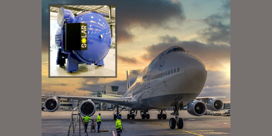
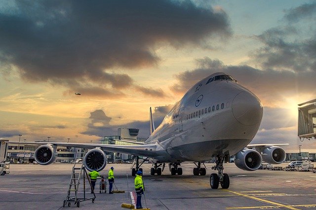
Source: Unsplash.com/Willian Justen de Vasconcellos
That’s a little bit of the background of the 0.1° readability.
Doug Glenn: So, basically, we’re in a situation, now, where people are, in fact (and correct me if I’m wrong here), potentially going to fail SATs or tests on their system because of a 0.1° reading, correct? I mean, it is possible, correct?
Andrew Bassett: Yes. So, when the 0.1° readability came out in Rev F, we gave it a two-year moratorium that with that requirement, you still had two more years. Then, when Rev G came out, exactly two years to the date, we still had a lot of customers coming to us, or a lot of suppliers coming back to us, and saying, “Hey, look, there’s a supply shortage on these types of recorders. We need to buy some time on this.” It ranged from another year to 10 years, and we’re like — whoa, whoa, whoa! You told us, coming down the pike before, maybe you pushed it down the road, whatever, probably Covid put a damper on a lot of people, so we added another year.
So, as of June 30th of 2023, that requirement is going to come into full play now. Like it or not, that’s where the standard sits.
Doug Glenn: So, you’re saying June 30th, 2023?
Andrew Bassett: Yes.
Doug Glenn Alright, that’s good background.
I guess there were several issues that I raised. First off, you’ve already hit on one. I understand the ability to be precise, but in most heat treatment applications, one degree is not going to make a difference, right? So, why do we push for a 0.1° when 1° isn’t even going to make a difference?
Andrew Bassett: We know that, and it’s been discussed that way. But, again, that hard line in the sand had to be drawn somewhere, and that was the direction the community wanted to go with, so we went with that. Yes, we understand that in some metals, 10 degrees is not going to make a difference, but we need to have some sort of line in the sand and that's what was drawn.
Doug Glenn: So, a Class 1. I was thinking the lower number was a tighter furnace. So, a Class 1 (±5), and you’re saying, that’s all the furnace is classified for, right, ±5? So, if you get a reading of 1000°, it could be 1005° or it could be 995°. Then, you’re putting on top of that the whole idea that your temperature reading has got to be down to 0.1°. There just seems to be some disconnect there.
So, that was the first one. You also mentioned the instrumentation. It’s been pointed out to me, by some of the instrumentation people, that their instruments are actually only reading four digits. So up to 99.9 you actually have a point, but if it goes to 1000°, you’re out of digits; you can’t even read that. I mean, they can’t even read that down to a point.
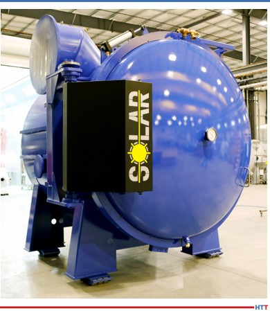
Source: Unsplash.com/Getty Images
Andrew Bassett: Correct. On the recording side of things, we went away from analog instrumentation. The old chart papers, that’s all gone, and we required the digital recorders with that 0.1° readability, as of June 30th of this year.
Again, the first draft was all instrumentation. That would be your controllers, your overtemps, and we know that limitation. But everyone does have to be aware of it. We still allow for this calibration of ±2 or 0.2%. If you’re doing a calibration, let’s say, on a temperature control on a calibration point at 1600° and the instrument only reads whole numbers, you can use the percentage, but you would have to round it inward. Let’s use 1800°, that would be an easier way to do it. So, I’m allowed ±2 or 3.6° if I’m using the percentage of reading, but if the instrument does not read in decimal points for a controller or overtemp, you would have to round that down to ±3°.
Doug Glenn: ±3, right; the 0.6° is out the window.
Andrew Bassett: Correct. I shouldn’t say we like to bury things in footnotes, but this was an afterthought. In one of the footnotes, in one of the tables, it talks about instrumentation calibration that people need to be aware of.
Doug Glenn: Let’s just do this because I think we’ve got a good sense of what the situation is, currently. Would you care to prognosticate about the future? Do you think this is going to stand? Do you think it will be changed? What do you think? I realize you’re speaking for yourself, here.
Andrew Bassett: I’m conflicted on both sides. I want to help the supply base with this issue but I’m also on the standards committee that writes the standard. I think because we’re so far down the road, right now — this requirement has been out there since June 2022 — I don’t see anything being rolled back on it, at this point. I think if we did roll it back, we have to look at it both ways.
If we did roll this back and say alright, let’s just do away with this 0.1° readability issue, we still have to worry about the people processing in Celsius. Remember, we’re pretty much the only country in the world that processes in Fahrenheit. The rest of the world has been, probably, following these lines all along. If we rolled this back, just think about all the people that made that investment and moved forward on the 0.1° readability and they come back and say, “Wait a minute. We just spent a $100,000 on upgrading our systems and now you’re rolling it back, that’s not fair to us.”
At this point, with the ball already rolling, it would be very interesting to see when Nadcap starts publishing out the audit findings when it comes to the pyrometry and this 0.1° readability to see how many suppliers are being hit on this requirement and that would give us a good indication. If there are a lot of yeses on it then, obviously, a lot of suppliers haven’t gone down this road. My guess is, for the most part, anybody that’s Nadcap accredited in heat treating — and this goes across chemical processing, coatings, and a few other commodities — I think has caught up to this.
Personally, I don’t think this is going to go away; it’s not going to disappear. It’s going to keep going down this road. Maybe, if people are still struggling with getting the types of devices that can have that 0.1° readability, then maybe another year extension on it, but I don’t know where that is right now. I haven’t gotten enough feedback from aerospace customers that say, "Hey, I can’t get the recorder." I mean,
Doug Glenn: I just don’t understand, Andrew, how it’s even physically possible that companies can record something as accurately as 0.1° if the assembly or thermocouple wire is rated at ±2°? How is that even possible that you can want somebody to be accurate down to ±0.1° when the thing is only accurate up to ±2°?
Andrew Bassett: Right, I get that. We can even go a lot further with that and start talking about budgets of uncertainty. If you look at any reputable thermocouple manufacturer or instrument calibration reports that are ISO 17025, they have to list out their measurements of uncertainty, and that gives you only the 98% competence you’re going to be within that accuracy statement.
Yes, I get the whole issue of this .1° readability. There were good intentions were to fix a flaw, and it spiraled. We’ve seen where PLCs and some of these high logic controllers now can show the .1° readability, but they automatically round up at .5°. Are you now violating the other requirements of rounding to E29? Now, I think we’ve closed out the poll in the standard, but you’re right. We were trying to do the right thing. Personally, I don’t think we gave it all that much further thought on that except hey, let’s just make recorders this way and this should be okay.
Doug Glenn: Right. No, that’s good. Let me be clear, and I think most everybody that was involved with the standards are excellent people and they’re trying to do the right thing. There is no dissing on anybody that was doing it. I’m not a furnace guy, right, I’m a publisher — but when I look at it, I’m going: okay, you’re asking somebody to be as accurate as 0.1° on equipment that can only do ±2°. That’s a 4° swing and you’re asking them to be within 0.1°, basically.
Andrew, this has been helpful. It’s been good hearing from you because you’re on the frontline here. You’ve got one foot firmly planted in both camps.
Andrew Bassett: I’m doing my best to stay neutral with it all.
Doug Glenn: Anyhow, I appreciate it, Andrew. You’re a gentleman. Thanks for taking some time with us.
Andrew Bassett: Thanks, Doug. Appreciate it.
About the expert: Andrew Bassett has more than 25 years of experience in the field of calibrations, temperature uniformity surveys, system accuracy testing, as well an expertise in pressure, humidity, and vacuum measurement calibration. Prior to founding Aerospace Testing & Pyrometry, Andrew previously held positions as Vice President of Pyrometry Services and Director of Pyrometry Services for a large commercial heat treater and Vice President and Quality Control Manager for a small family owned business.
For more information: Andrew Bassett at abassett@atp-cal.com or visit http://www.atp-cal.com/
Doug Glenn at Doug@heattreattoday.com

Doug Glenn
Publisher
Heat Treat Today
To find other Heat Treat Radio episodes, go to www.heattreattoday.com/radio .
Search heat treat equipment and service providers on Heat Treat Buyers Guide.com