Heat TreatTodayis privileged to present the inaugural 40 Under 40 Class of 2019, a group of young, up-and-coming talent in the North American heat treat industry. On Friday, October 4, 2019, we will introduce this group of industry elite, significant contributors to the heat treat market.
Be sure to check back here on Friday, October 4, where you can read about how this class is breaking barriers, saying yes to challenges, resolving the impossible, and reinforcing the culture of hard work and customer service. They are the reason the future of this industry is bright!
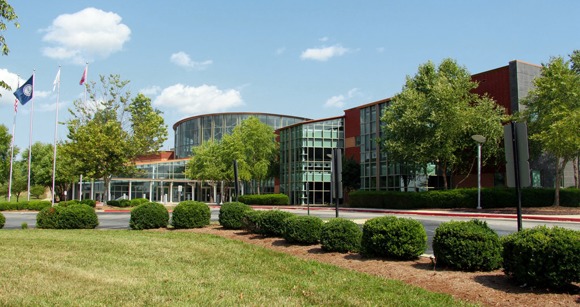
A German developer and provider of 3DMP metal 3D printers and technology recently announced that the company will open its first U.S. manufacturing facility in Danville, Virginia.
Gefertec LLC will introduce its 3DMP® technology, based on modern arc welding, for the production of metallic parts.
Andrea Clark, president of Gefertec, LLC
“Gefertec is excited to announce the opening of our Danville—Pittsylvania County location as our first U.S. location for our 3DMP® additive manufacturing business,” said Andrea Clark, president of Gefertec, LLC.
Tobias Roehrich, CEO of Gefertec GmbH
“This is in alignment with our long-term commitment to Danville and the Institute for Advanced Learning and Research, and we are excited to expand our business to the U.S.,” said Tobias Roehrich, CEO of Gefertec GmbH. “Danville has been chosen for its excellent business and community support and its involvement in the advanced manufacturing sector.”
Conventional wisdom says that batch processing is for smaller volumes. Anytime large volumes of 1 million or more parts per year are envisioned, for instance with ferritic nitrocarburizing, the go-to technology is a roller hearth or other continuous systems like rotary retort or mesh belt furnace. In this article, which originally appeared in Heat Treat Today’sJune 2019 Automotive print edition, Mark Hemsath urges end-users and engineers who use, or specify, continuous systems to not undervalue automated batch processing for large volume production.
There are a number of trends in the automotive arena:
More parts are being light-weighted. This means they need more precise and repeatable heat treating.
Parts need to be cheaper and lighter. The trend we see are increased and more sophisticated stampings.
The trend is away from carbonitriding and toward ferritic nitrocarburizing due to less distortion on lighter parts.
Gears and such are smaller and require exact carburizing, minimized quench distortions, and less hard machining.
A deep discussion of all of these is beyond this article, but we will touch on each as we focus on nitrocarburizing for large-volume production.
Batch v. Continuous
What is the difference between a classic “batch” furnace and a classic “continuous” furnace? The answer is material handling. By definition, heat treating is a “batch” operation. In virtually all instances, the product must be brought to temperature and held—or “soaked”—for a specific time. Ferritic nitrocarburizing is no different. This ramp heat, hold, and cool is a “batch”. Thus, virtually all heat treating is batch and only material handling is the difference. The basic difference is that in batch we move the product in its cold state and heat it in one place (batch). In continuous furnaces, we move it while it is heating.
Advances in Material Handling
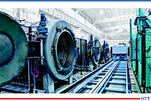
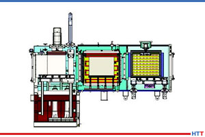
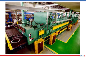
Figure 1: Roller hearth conveyor furnace with heating section, cooling tunnel and after cooling. Note the right angle turn via automatic conveyors to meet space requirements.
Advanced, fully automated, and reliable material handling has made great advances over the last two decades from more recent industries like Amazon, where millions of packages need to be moved through the shipping process, to older industries like heat treating which moves steel parts through furnaces and other equipment. Automation, such as conveyors with self-driven rollers and photo sensors or proximity switches, or robots and automated self-guided vehicles—all coordinated by a PLC—have made material handling more reliable. Manufacturers have a lot of options.
A continuous furnace like a roller convey-or—or “roller hearth”—furnace conveys the product while it is heating (Figures 1, 5 & 8). A mesh belt furnace conveys parts while heating, and a rotary retort furnace (Figure 4) moves parts via a heated rotating barrel to the next process step which is typically cooling or quenching. Moving parts while hot is a challenge, but reliable high volume heat treating is why these furnaces have seen such success over the years. Roller furnaces and rotary retort furnaces are still built and used in a wide variety of industries, and they make sense for a number of reasons. Lower energy use is one main factor.
With robots placing the load, both batch and continuous processes can be fully automated. With such options, batch processing has increased in use.
Automated Batch
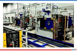
Figure 2: The doors have actuators for automatic opening.
A leading manufacturer of heat treating furnaces has implemented the high volume automation approach many times using batch technologies. In 2013, a fully automated batch FNC installation for gears was installed for processing 1 million gears annually.[1] As a result of this success, the customer added more batch furnaces to the line.
The furnaces in Figures 2 and 3 are retort-based nitriding and ferritic nitrocarburizing furnaces. With automatically opening doors, complete PLC control, and automated batch load movement, no humans are needed. A load car operates in both directions for a heavy load of two metric tons or more, allowing furnaces to be placed facing each other.
Automated, High-Volume System Design
Figure 3: This line consisted of pre-oxidizing ovens on one side to save time in the more expensive FNC furnaces. Cooling stations after heating are also added to reduce time in the batch furnace and make the parts safe for handling.
As mentioned, the company supplied nitrocarburizing technology using its ZeroFlow™ method (Figures 2 and 3) for an automated thermal treatment line for the production of a variety of gears. The line consisted of six large, front-loaded retort-style batch furnaces, a four-chamber vacuum washer, two ovens for pre-activation in air, additional post-cooling of the furnace charges, and an automatic robotic loader/unloader, which ensured charge transport within the system (seen in Figure 3). The automated line also included safety monitoring. System workload dimensions were 32″ wide x 32″ high x 60″ long with a gross workload capacity of 4,400 pounds. Production totaled 2,000 pounds of gears per hour. Good equipment design, retort technology, and use of ZeroFlow control technology resulted in a very successful project.
Cooling the Load and Vacuum Purging
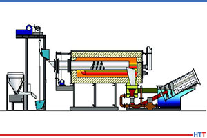
Figure 4: Whirl-Away Quench on a Rotary Retort line for small part efficient quenching/cooling.
There are advantages to continuous furnaces like a conventional roller hearth furnace; however, special options like fast cooling and vacuum purging present challenges to these conventional furnace designs. In batch, this is usually not a problem. Vacuum (and even cooling) is more difficult to attempt in continuous variations due to sealing challenges in the chamber designs. An example of a good solution is the rotary retort furnace shown in Figure 4, which offers single piece quenching where each piece falls into a water or oil quench and is “whirled-away,” a continuous furnace design which works well for small parts with a relatively small footprint. In batch, the whole load needs to be quenched together; this can present challenges that understanding the part needs and configurations can lead the process engineer to different solutions.
In a roller furnace, slow cooling means the furnace gets longer (Figure 1).
Variations in Continuous Batch – Semi-Continuous Processing
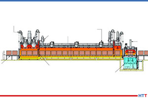
Figure 5: Hardening roller conveyor furnace with integral pre-heat and oil quench system
In Figure 6, an automated batch hardening line is shown. In Figure 7, the same process is shown, but with an added pre-heat chamber to allow faster processing via the pre-heat and use the single quench in a more productive manner. An oil quench is an expensive piece of equipment. The cycles are also always much shorter for quenching than heating, so we want to maximize the use of the quench. In a pure batch system, you need one quench per furnace. In the semi-continuous approach, the quench is used more frequently and there is higher productivity per capital dollar invested. In a roller hearth or rotary retort installation, the quench can be properly sized to handle all of the heating production. In an installation using pure batch systems, there might be 3 to 6 quench tanks. In a fully continuous roller furnace, there would be one quench (see Figure 5).
Figure 6: This automated batch line is for low pressure carburizing and vacuum hardening, with oil quench, automated washer, and batch temper furnace. The smart loader makes the cell fully automated.
Case History and Take-Aways
The automated batch system referred to in Figures 2 and 3 went online in 2014 and is currently operating at full capacity, while meeting the stringent requirements of the automotive industry. It achieved the planned production goal of 1 million gears per year with 99% process reliability and 98% equipment availability. The customer previously had a continuous conventional pusher furnace. The new line achieved an 80% reduction in the consumption of ammonia from that consumed using in the pusher furnace to nitrocarburize. Endothermic gas was also eliminated by the supply of a new methanol CO generator as the carbon source in the process.[1]
Figure 7: Triple chamber vacuum hardening line with oil quench and pre-heat chamber. Tray flow is right to left.
The take-away from this successful project is that in order to increase production even more, automated batch systems need to exhibit two factors to compete with a continuous system like a roller hearth furnace. First, the loads need to be optimized and very densely packed. Second, the batch loads need to be larger than the continuous loads. A standard size of 40″ x 40″ x 60″ has since been created which has 50% more volume than the unit in the example above. Making the furnace a bit larger is not that difficult. Additionally, in a recent application, CFC tooling has been utilized to assure more dense loading geometry with much lighter parts, giving reliable rack geometry for a load of 1,000 pieces.
Gas Usage – Benefit Batch
Figure 8: Cooling tunnel and exit of continuous roller hearth furnace for instrument transformer electrical steels annealing.
The biggest advantage of batch furnaces is the lower process gas usage. In continuous furnaces, in order to keep the process safe and clean, pressure must be maintained by flowing a significant volume of gases. With the constant opening of doors during the process and the need to keep operating pressures high enough to prevent air infiltration, atmosphere gas usage is always high. To keep the costs down, gases are typically generated with the use of an endothermic generator (40% Nitrogen, 40% Hydrogen, and 20% CO) or a lean exothermic generator with a low dewpoint. In all instances, the generator is another piece of thermal equipment to maintain and purchase.
Energy Costs – Benefit Continuous
In most instances, batch processing uses more energy—or more expensive energy—such as electricity. Electricity costs can vary tremendously from location to location whereas natural gas prices are more consistent and lower. Batch nitriding furnaces are available in gas-fired heating options at an added capital cost. However, the batch process still uses more energy per pound. If electricity is available at a reasonable rate, then the difference is not as great on a per pound basis. In a recent analysis, it was estimated that an electrically heated batch system came to cost the equivalent of about $0.06 per pound of FNC operating costs, versus $0.03 per pound of FNC operating costs in a continuous gas-fired variation (energy and consumables only).
Summary
Batch or continuous in large volume scenarios is no longer a clear-cut answer. Your heat treating professional and your furnace suppliers should understand this. There are literally dozens of variables that need to be assessed, and only after a careful analysis tailored for each customer can an optimized solution be designed with either batch or continuous furnace solutions.
Notes
1. Hemsath et al, “Nitrocarburizing Gears using the ZeroFlow Method in Large-Volume Production”, Thermal Processing, 10/2015
About the Author: Mark Hemsath is Director of Nitriding and Special Vacuum Furnaces at SECO/VACUUM Technologies, LLC and acting Thermal General Manager at SECO/WARWICK Corp. in Meadville, Pennsylvania. With 30 years of experience in the industrial furnace and heat treat equipment market, he is in charge of all North American atmosphere furnace sales, gas nitriding, and gas carburizing. This article originally appeared in Heat TreatToday’sJune 2019 Automotive print edition and is published here with the author’s permission.
A medical device manufacturer has upgraded its in-house heat treating capabilities with a dual-chamber furnace system, which will give the company the same pyrometry requirement in its medical device production as materials and parts produced for the aerospace and defense industry in terms of furnace/oven calibration, classification and performance requirements.
Richard Conway, DELTA H chief technology officer and founder
Straits Orthopaedics in Penang, Malaysia, commissioned DELTA H TECHNOLOGIES for a second dual-chamber aerospace heat treat (DCAHTTM) furnace system. The furnace system, controls, and software are designed for full compliance to the medical accreditation program “MedAccred” as well as the US FDA’s recent recognition and adoption of the Society of Automotive Engineers (SAE) Aerospace Materials Specification 2750 (AMS2750) pyrometry standard.
Mr. TH Su, CEO of Straits Orthopaedics
“Previously medical device pyrometry standards varied somewhat from manufacturer to manufacturer,” said Richard Conway, DELTA H chief technology officer and founder. “With the adoption of the well-established AMS2750 standard, there is a consistent requirement across the industry. For DELTA H this is an exciting opportunity in a market that now has the same uncompromising demands for performance and accountability which our thermal processing systems are designed for.”
“DELTA H is making great contributions to our heat treating technology which is delighting all our customers,” Mr. TH Su, CEO of Straits Orthopaedics.
A multinational manufacturer of ships, industrial machinery, and aircraft headquartered in Tokyo, Japan, recently entered into an agreement to acquire the regional jet program from a Montreal-based manufacturer of regional airliners, business jets, and equipment for public transport.
Mitsubishi Heavy Industries, Ltd. and Bombardier Inc. announced they have entered into a definitive agreement, whereby MHI will acquire the maintenance, support, refurbishment, marketing, and sales activities for the CRJ Series aircraft, including the related services and support network located in Montréal, Québec, and Toronto, Ontario, and its service centers located in Bridgeport, West Virginia, and Tucson, Arizona, as well as the type certificates.
Seiji Izumisawa, president and CEO of MHI
“This transaction represents one of the most important steps in our strategic journey to build a strong, global aviation capability. It augments these efforts by securing a world-class and complementary set of aviation-related functions including maintenance, repair, and overhaul (MRO), engineering and customer support,” said Seiji Izumisawa, president and CEO of MHI. “The CRJ program has been supported by tremendously talented individuals. In combination with our existing infrastructure and resources in Japan, Canada and elsewhere, we are confident that this represents one effective strategy that will contribute to the future success of the Mitsubishi SpaceJet family. MHI has a decades-long history in Canada, and I hope this transaction will result in the expansion of our presence in the country and will represent a significant step in our growth strategy.”
Alain Bellemare, president and CEO, Bombardier Inc.
“We are very pleased to announce this agreement, which represents the completion of Bombardier’s aerospace transformation. We are confident that MHI’s acquisition of the program is the best solution for airline customers, employees and shareholders. We are committed to ensuring a smooth and orderly transition,” said Alain Bellemare, president and CEO, Bombardier Inc. “With our aerospace transformation now behind us, we have a clear path forward and a powerful vision for the future. Our focus is on two strong growth pillars: Bombardier Transportation, our global rail business, and Bombardier Aviation, a world-class business jet franchise with market-defining products and an unmatched customer experience.”
The CRJ production facility in Mirabel, Québec, will remain with Bombardier. Bombardier will continue to supply components and spare parts and will assemble the current CRJ backlog on behalf of MHI. CRJ production is expected to conclude in the second half of 2020, following the delivery of the current backlog of aircraft.
An oil and gas OEM specializing in technology, products, and services recently announced it will expand its heat treating capabilities when it assumes responsibility of a Houston-based oilfield services company’s forging operations.
Under the terms of the agreement, AFGlobal, based in Houston, Texas, will assume all operational responsibility in its assumption of Dril-Quip’s forge facilities and equipment located at its Houston manufacturing campus with an option to acquire those same assets. AFGlobal will supply Dril-Quip with its forging needs while also using the assets to further support AFGlobal’s OEM business in the broader oil and gas market as well as other existing markets, including industrial, aerospace, defense, and transportation.
Curtis Samford, president and CEO for AFGlobal
“We are excited to partner with Dril-Quip, not only for their forging needs but also to strengthen our offering for our core energy clients in drilling and pressure pumping,” commented Curtis Samford, president and CEO for AFGlobal. “Furthermore, we see this as another major step in our ongoing expansion into the broader industrial, aerospace, defense, and transportation markets. This equipment significantly expands our existing capabilities in both open- and closed-die forging and nearly doubles our ring rolling capability and capacity. These assets also provide us with further expansion opportunities for heat treating and machining.”
A global leader in primary and metalworking industrial process fluids recently announced an agreement to acquire the operating divisions of a UK company that provides specialty chemicals, operating equipment, and services to industrial end markets.
Quaker Houghton plans to purchase Norman Hay plc, which serves a number of industries including aerospace, automotive, oil and gas, and power generation through four divisions:
Ultraseal, a leading global provider of impregnation technology, including porosity sealants, and associated chemistry and equipment for die cast components;
SIFCO ASC, a leading global provider of surface treatment solutions through selective electroplating, anodizing, chemical solutions and engineering solutions;
Surface Technology, a specialty provider of surface treatment solutions including coatings, thermal sprays, plating and other ancillary services; and
Norman Hay Engineering, a leading provider of design and engineering services that support surface treatment plants and equipment for the Ultraseal, SIFCO ASC and Surface Technology businesses as well as additional third-party industrial engineering applications.
Michael F. Barry, chairman, CEO, and president of Quaker Houghton
Quaker Houghton intends to operate the acquired divisions as a stand-alone business within its Global Specialty Businesses platform while it completes the integration of Quaker Chemical and Houghton International.
“This acquisition represents an opportunity to add new technologies with good growth characteristics in attractive core market segments with high barriers to entry such as die-casting, automotive OEM and aerospace,” said Michael F. Barry, chairman, CEO, and president of Quaker Houghton. “We also believe it provides a strategic opportunity to take advantage of external market trends such as the light-weighting of vehicles and 3D printing where we have the opportunity to leverage our global footprint and complementary geographic strengths. In addition, Norman Hay’s engineering expertise, which includes robotics applications, strengthens the existing equipment solutions platform inside Quaker Houghton and further positions the Company for Industry 4.0.”
Norman Hay plc was established in 1946 as a decorative electroplating business and has evolved into a global specialty chemicals sealant, surface coatings, and engineering group. The company is headquartered at its modern, state of the art production facility in Coventry, England. The company has approximately 400 employees with production and R&D facilities across Europe and the United States.
This article was written by Dr. Vadims Geza, chief scientist at CENOS. More information on CENOS Platform can be found here.
Induction is becoming an increasingly popular choice for heating steel billets prior to forging due to its ability to create high heat intensity quickly and within a billet, which leads to low process-cycle time (high productivity) with repeatable high quality, occupying minimal space on the shop floor. It is more energy-efficient and inherently more environmentally friendly than most other heat sources for steel billets.
In this article, the author demonstrates a simulation example on how to optimize a progressive induction heating system for a steel billet. The method used is CENOS Platform, a 3D simulation software which focuses specifically on induction heating and uses open source components and algorithms.
CENOS platform is capable of simulating various types of induction heating for forging. It is possible to simulate both static heating and progressive heating where the billet is moved through the coil with constant velocity. In accomplishing this simulation, coil design is not a limitation: both single coil and multi-coil are possible to simulate. Besides the coil, it is also possible to simulate any material and frequency.
The functional performance of the software
CENOS is a finite element method-based, computer-aided engineering desktop software for 2D and 3D physical process simulation and computational modeling of induction heating, induction hardening, brazing, annealing and tempering of steel, aluminum, copper, and other materials.
The simulation process consists of three steps:
Choose the workpiece geometry (from built-in templates or create your own CAD file).
Define induction heating parameters (frequency, voltage, time, etc.).
Run 2D or 3D simulation of your choice.
At the conclusion, results like temperature and magnetic field are displayed in 3D renderings, plots, and more. Apparent power, induced heat, and inductance are logged into an Excel file.
3D Simulation example—comparison of two heating systems
In the simulation, two systems under consideration—two-stage and three-stage systems—in the progressive heating of the billet. The target for the simulation was to reach 2192°F (1200°C) ± 122°F (50°C). To check both systems, the user has to create set up for both of them, set physical parameters (material properties, frequency, current, etc.), and start the simulation.
After the simulation is done, the user will have access to different output variables, including:
Temperature distribution
Current density and Joule heat distribution
Magnetic field lines
Total, reactive and apparent power
Inductance of the coil
Coil current, voltage
In our example of billet heating, it is possible to compare both cases and the output.
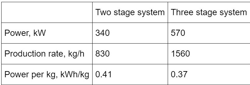
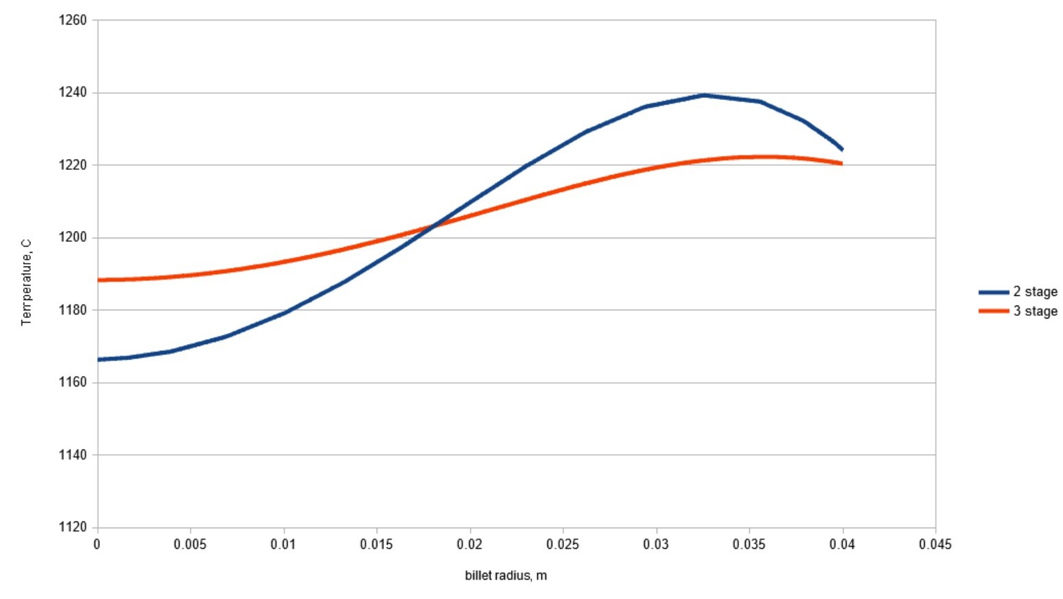
It is observable how a three-stage system can decrease power consumption and increase the production rate for this specific case. It is also possible to plot the distribution of temperature, Joule heat, magnetic field, etc. Resulting temperature distribution in the billet across the radius is shown in Figure 1. As can be seen, better temperature homogeneity is obtained in the three-stage system.
Figure 1. Temperature distribution along the billet radius at the outlet of the heating system
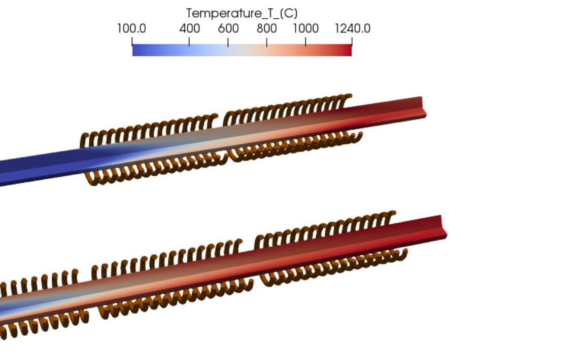
Figure 2. Temperature distribution in the long billet during scanning (progressive) induction heating.
Figure 2 shows how different systems lead to different temperature distribution. In the two-stage system, the temperature required for forging is reached with shorter coils, thus also with smaller scanning speed. This leads to worsened temperature uniformity and smaller production rates. On the other hand, the three-stage system heater gradually increases the temperature of the billet and the resulting temperature difference between core and surface is smaller.
Platform users are free to change all the input parameters and assemble the system of any number of stages required for their process.
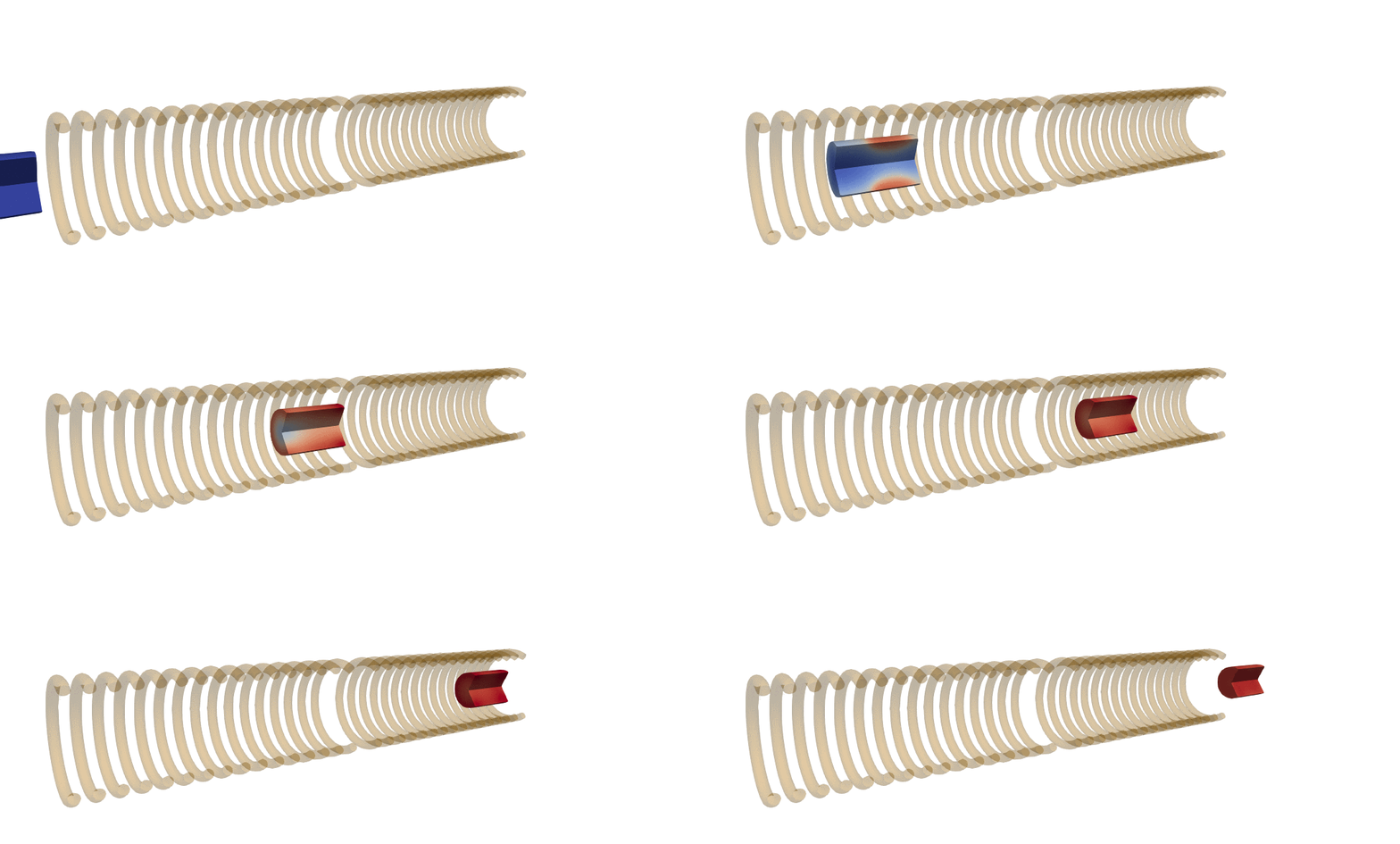
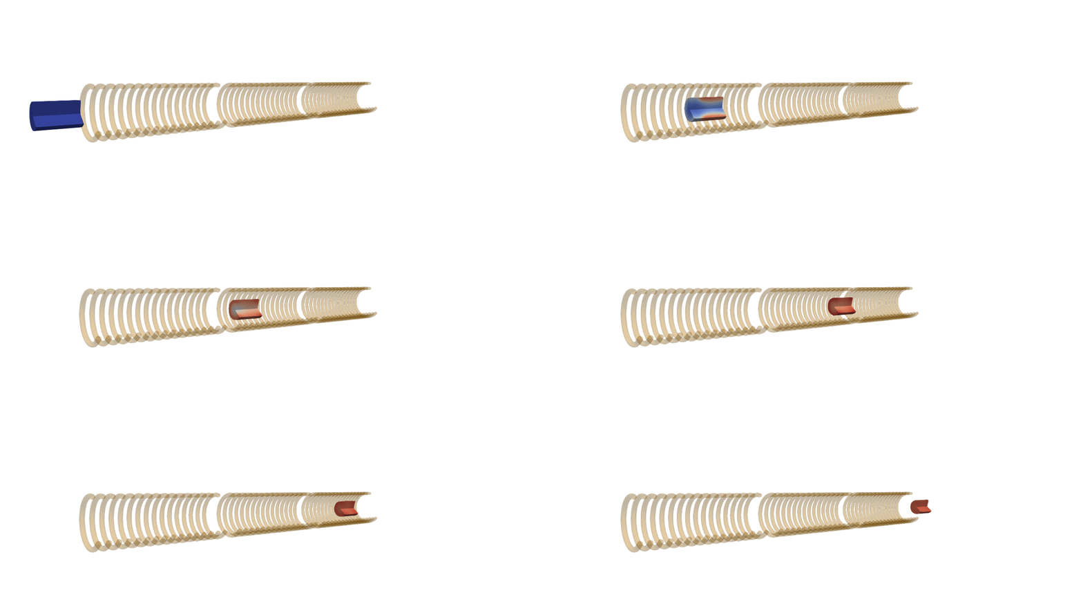
Should the same system need to be used for scanning of shorter billets where end effects play a more significant role, it is possible to set up a simulation with a moving billet. An example of temperature dynamics in such simulation are shown in GIF images below:
A simulation with a moving billet in a two-stage system.
A simulation with a moving billet in a three-stage system.
Simulation helps make better decisions for production set-up and planning
As demonstrated in the simulation example, it is possible to compare two different systems and get results. The scope and variety of different simulations are unlimited; it all depends on what problem the user wants to solve:
Dr. Vadims Geza
Heating system design—to optimize induction heating performance, improve product quality, and avoid unpleasant surprises related to subsurface overheating
The selection of power, frequency, and coil length in induction billet heating applications
The selection of right forging temperatures for plain carbon and alloy steels to avoid possible damage by incipient melting or overheating.
Main Photo Image via CENOS, courtesy of efd-induction.com
A UK-based provider of hot form quench (HFQ®) technology recently joined forces with an auto parts manufacturer to bring HFQ® technology to the North American market.
ITL’s CEO, Jonathan Watkins
The creator of HFQ® technology, Impression Technologies Ltd (ITL), a leading advanced lightweighting solution for high-strength aluminum structures, has partnered with Telos Global in Caryville, Tennessee, with the latter taking on the production of high-strength aluminum body-in-white and chassis HFQ® components, enabling the company to service OEM requirements in the SUV, pick-up truck, and electric vehicle markets. Telos will manufacture HFQ® components at its facility in Caryville, Tennessee, before expanding into Asia and Europe.
Rick Teague, CEO and founder of Telos Global
“We are delighted to have entered this strategic partnership with Telos Global, which will offer automotive OEMs a high-volume supply base for stronger, lighter, more cost-effective structures made using HFQ® Technology to a guaranteed standard,” said ITL’s CEO, Jonathan Watkins. “We look forward to working with Telos to develop a global HFQ® supply chain capability in North America as well as globally.”
“This partnership with ITL offers Telos an exciting opportunity to supply automotive customers in North America and around the world with complex components manufactured from new, high-strength aluminum alloys,” said Rick Teague, CEO and founder of Telos Global. “We believe HFQ® Technology, using Telos’ scalable production system, will offer significant opportunities for light-weighting and design flexibility at a competitive price.”
Heat Treat Today readers are invited to meet our team at Heat Treat in Detroit and we want to make it easy for you!
Use the HTS Expo Fast Pass option, and you can avoid the $50 registration fee and gain complimentary access to the exhibit hall. Your first stop, of course, will be at the Heat Treat Today booth at #2123.
Just go to www.asminternational.org/heattreat to pre-register using the discount code EXPOFREE, which is valid Tuesday–Thursday during expo open hours and will give you access to everything on the expo show floor.