A North American-based manufacturer of helicopter masts, turbine shafts, engine thrust links, and nuclear components with in-house heat treating will receive a customized vacuum tempering/gas nitriding furnace. The furnace will be used for nitriding and nitrocarburizing loads up to 63" diameter x 175" deep and has a load capacity of 13,200-lb.
Peter Zawistowski Managing Director SECO/VACUUM TECHNOLOGIES, USA Source: secowarwick.com
The manufacturer ordered the custom-made pit nitriding furnace from SECO/VACUUM to increase load capacity. In addition to being able to process oversized workloads, the furnace, with an almost 80% increase in size from the standard, has a working temperature range of 300°F–1,300°F, a temperature uniformity of +/-5°, and low ammonia consumption.
"We are very pleased to collaborate with this precision manufacturer to enable new state-of-the-art nitriding and nitrocarburizing capabilities in their Canadian facility," commented PeterZawistowski, managing director of SECO/VACUUM.
A worldwide supplier of high-temp piezo ceramics in the military, aerospace, and medical fields will receive a floor-standing, high-temperature, silicon carbide furnace. The furnace, powered by high-density silicon-carbide elements, will be used for processing glass products to 2,500°F.
L&L Special Furnace Co., Inc. will provide the furnace, model GLF836, which has a work zone of 18"x18"x36" with a double pivot horizontal door. The furnace, constructed from high-alumina refractory (with reduced silica), will help to delay the corrosive reaction between silica and the lead outgassing at elevated temperatures.
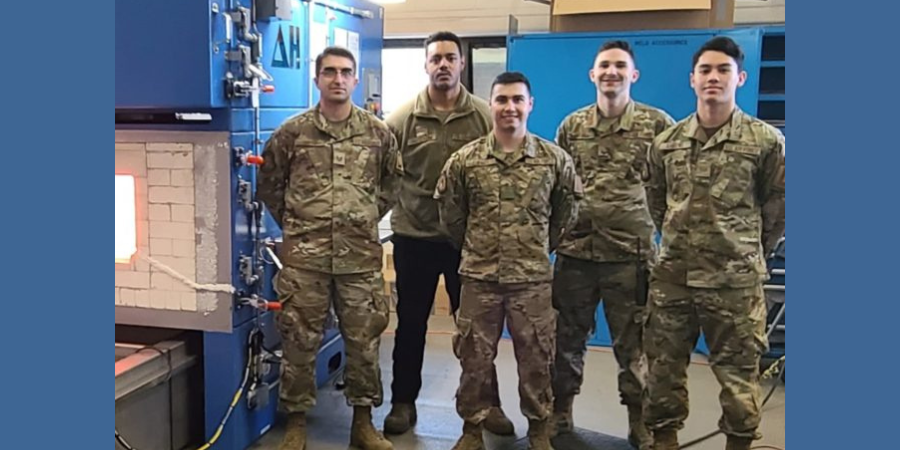
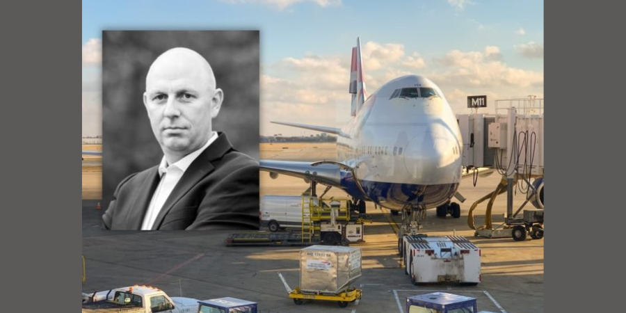
United States Air Force personnel stationed at Royal Air Force (RAF) Base Mildenhall in the United Kingdom recently commissioned and received full training on the use and maintenance of a heat treating furnace for aerospace parts. The furnace will help maintain KC-135, CV-22, C-130 aircraft, and F-15 fighter jets assigned to RAF Mildenhall or nearby RAF Lakenheath air stations. The installation was interrupted by an impromptu visit from the U.S. President.
Richard Conway Chief Technology Officer Delta H Technologies
The DELTA H® TECHNOLOGIES dual chamber heat treating furnace for aerospace (DCAHT®) was designed by the supplier to rapidly heat treat all common aviation grade metals and alloys necessary for aircraft maintenance and is fully compliant with USAF/NAVAIR Tech Order 1-1A-9 and SAE-AMS2750F. The training received by the USAF airmen at RAF Mildenhall included essential instructions in heat treating, as well as furnace calibration practices like temperature uniformity surveys (TUS) and system accuracy tests (SAT) and culminated with each airman receiving Certificates of Training.
The specialized furnace features an upper chamber convection system, 18" wide x 12" high x 48" deep, capable of Class 1 (+/-5°F) from 200°F to 1200°F and a lower chamber radiant heat system, 12" wide x 12" high x 36" deep, capable of Class 3 (+/-15°F) from 1000°F to 2000°F with air or argon atmosphere. A roll-away quench tank features dual baths for water and oil quenchant. The controls and data acquisition provide detailed batch records of heat treated parts, including quench delay, as well as automatic tracking of thermocouple usage and calibration intervals.
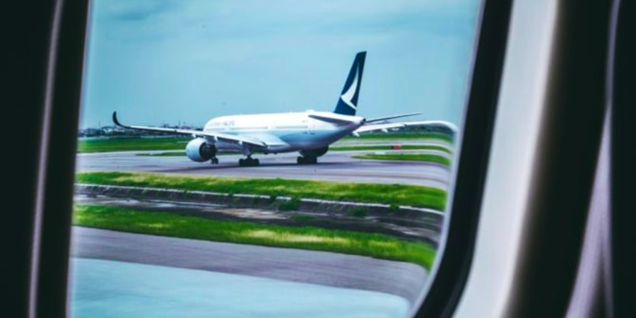
Air Force One at RAF Mildenhall
The training was interrupted by an unexpected visitor to RAF Mildenhall. The hangar next to the Metals Tech Shop, where the furnace was being commissioned and the training was being conducted, was the epicenter for the arrival of a top-secret VIP. When the Air Force Band began practicing "Hail to the Chief," it became obvious that U.S. President Joe Biden would be making an unexpected visit to the base. While the President’s visit was not related to the furnace commissioning, Richard Conway, DELTA H® founder and chief technology officer, and wife Mary Conway, witnessed this presidential visit and got a few candid photographs of Air Force One (see above).
Heat treating any aerospace projects? Then you know titanium is up there when it comes to VIP alloys in the industry. This best of the web is pulled from an aerospace magazine in which Michael Johnson of Solar Atmospheres answers five questions about creep flattening titanium:
Typical temperatures for creep flattening titanium parts
Whether of not creep flattening can only be done in a vacuum
Best fixturing for creep flattening titanium parts
Can creep flattening minimize movement
Will reheating titanium over 1,000°F affect certification
An excerpt:
"Give your heat treater your material certifications. Many mills will certify to aerospace material specification AMS 2801, AMS 4905, AMS 4911, AMS-H-81200, etc. The material often can be re-annealed while simultaneously creep flattening." - Michael Johnson, Director of Sales, Solar Atmospheres
A European machinery group will receive a vacuum furnace for hardening and tempering processes, and its design has been customized in order to meet the group’s need to harden aviation steel used as landing gear. The heat treatment solution will improve the process economy in European plants and is characterized, in part, by low energy consumption.
Maciej Korecki Vice President of Business for the Vacuum Furnace Segment SECO/WARWICK
To meet this particular application, SECO/WARWICK engineers fitted the Vector® vacuum furnace with a non-standard system for subquenching with liquid nitrogen that enables the required quick cooling down of landing gear components. The solution has also been expanded with a vacuum system designed with a diffusion pump and is equipped with a directional cooling option and convection heating system with a specially designed fan.
“This is already the fourth purchase order for a furnace from this product segment from this customer,” commented Maciej Korecki, VP of Business Segment for Vacuum Heat Treatment Furnaces at SECO/WARWICK, the sister company to North American heat treat supplier SECO/VACUUM. He also added that “The product solves the customer’s problem with the hardening of special aviation steel, significantly increases the capacity of the existing production line of this component, and also improves process parameters, since the current devices used by the customer are not fitted with a subquenching system using liquid nitrogen. It will certainly be one of the unique solutions completed this year.”
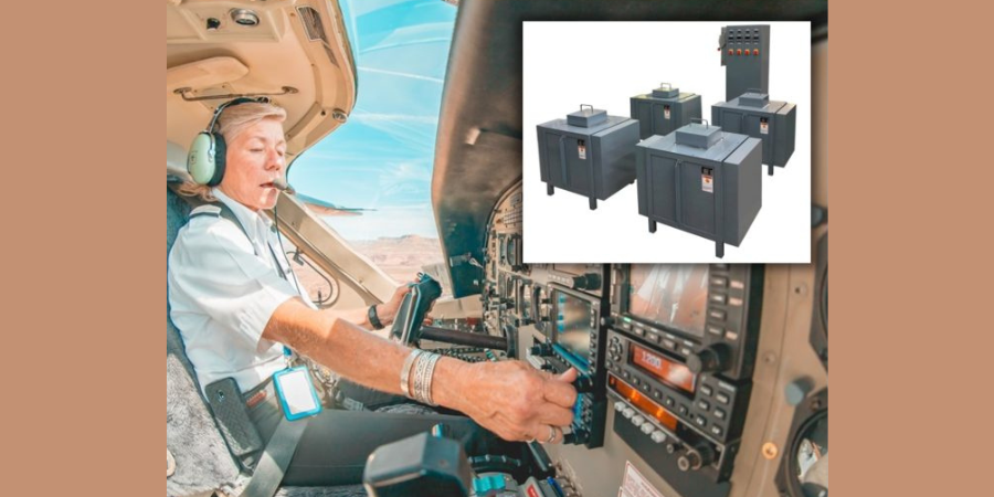
A multi-unit modular pot furnace system has been set for an aerospace manufacturer in the U.S. to help the end user increase heat treat capacity.
Each of the four Lucifer Furnaces Model 2057 pot furnaces is connected to a single freestanding NEMA 1 control panel. Each furnace is heated electrically with 18 KW of power to heavy duty coiled elements in removable holders on all 4 side walls. Roof and side covers bolted to the frame of each furnace can be removed for easy service access.
The units are insulated with 5" of multi-layer insulation consisting of dry-fit hot face lightweight firebrick backed by cold face mineral wool. A vestibule at the top of each furnace reduces heat loss between the pot wall and firing chamber. Controls onboard include Honeywell DC3500 digital multiprogrammable cascade controllers which automatically interpret multiple thermocouple readings and adjust the inside/outside pot temperature to achieve the desired set point. Additional energy efficiency and power uniformity is maintained with SCR power units.
Heat treat specifications can be tiresome to stay up-to-date on. So it’s great when we find digestible content on AMS2750F to share with you.
In today’s best of the web article, you’ll be able to review the 4 new requirements for process instrumentation and what 18 pieces of information must always be reported in the calibration certificate.
An excerpt:
“The recording tools used on heat treatment plants should not be used to record TUS or SAT sensor temperatures unless it can be demonstrated that the recording channels of the TUS and/or SAT sensors of an integrated system are separated from the recording system of the heat treatment furnace and also meet the requirements of the field test instrument.”
Heat TreatToday publisher Doug Glenn wraps up this three-part series with Pelican Wire experts by talking with John Niggle from Pelican Wire about thermocouple insulation types and considerations.
The first two episodes cover the history, types, vocabulary, standards, and other basics of understanding how thermocouples work. Listen to the previous episodes of the series here.
Below, you can either listen to the podcast by clicking on the audio play button, or you can read an edited transcript.
The following transcript has been edited for your reading enjoyment.
Doug Glenn (DG): Welcome to Heat TreatRadio!
John Niggle (JN): Yes, it's good to see you again, Doug. I know we've run into each other a couple of times out there in the field. I'm looking forward to having the opportunity to do all of this stuff in person again.
DG: It will be nice. Before we hit the record button, we were talking about shows this fall and hoping that they happen because you, like I, are ready to get out and go.
You are the business development manager for Pelican Wire. If you don't mind, give us just a little bit of background about you and about your experience in the whole thermocouple world.
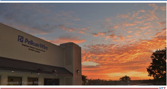
Pelican Wire headquarters
JN: Sure, absolutely. As you said, I am the business development manager at Pelican Wire. I've been at Pelican since 2013 so we're working out my eighth year here. I'm a career industrial sales representative. I do have previous experience also, actually, in the process instrumentation industry. Way back when, before I even knew how to spell thermocouples, I was selling that stuff when I first got out of college. My career has, sort of, gone full circle, let's say.
DG: Very nice. Well, you've got plenty of years of experience, which is great. We've had two previous episodes with your colleague, Ed Valykeo, and we covered a good bit of stuff. We covered a lot of basics in the first episode. We covered standardization, and things of that sort, in the second episode. I want to encourage any listeners who haven't listened to those episodes, feel free to go back, Google “Heat TreatRadio” and search for “Pelican Wire” and listen to episodes 1 and 2.
John, you and I want to move forward. I'm always kind of curious about this question: From your perspective, with your experience, why do we use thermocouples? Let's talk about what they are and why we use them.
JN: First of all, we have to assume that somebody is trying to measure the temperature of some sort of a process- a process or an event of some kind. That's basically what they're trying to do. Compared to other devices like RTDs, bimetal thermometers, liquid expansion state change devices and so forth, thermocouples are robust, they're inexpensive; they're repeatability, they're ease of use and size -- all of those factors lead them to be more widely used than another sort of thermal measurement device of any kind. It is the preferred method.
On top of that, I mentioned the expense part. Because they're relatively inexpensive, there are certain industries, the heat treat industry and smelting industry, for example, consider these as, actually, consumable or disposable. So, the cost factors in significantly in the industry that we're talking about here.
DG: I live in western Pennsylvania and the town where my wife grew up, there was an old Leeds and Northrup manufacturing plant. I believe they made the consumable thermocouples for melt shops. You would, basically, throw the thermocouple in and it would melt quickly but it would give you a response during that time.
CLICK to Listen!
JN: Right. And, as I mentioned earlier, the response factor is important, or that's one of the factors considered, when people are looking at thermocouple wire. And, you're correct, Ed Valykeo, as you mentioned, has 40 years of experience in the industry and has seen exactly the same sort of thing that you're talking about where people will just tack weld it onto something that gets thrown into a furnace or it gets thrown into a melting pot or something like that, and they're looking for that instantaneous temperature.
If you don't mind, I'll tell you that we've done some work, actually, in the aerospace industry and we had a customer that we sold significant, literally miles, of thermocouple wire to (when I say aerospace, it was specifically for space exploration) and this was because of whatever we had done with the insulation. I can't tell you, because it was before my time, but this is what was relayed to me- they were able to get another 3 - 4 seconds of temperature measurement out of that wire. That critical, extra data for them made all the difference in the world.
DG: We're going to get to the insulation part which should be interesting. You won't have to tell us any trade secrets, but we are headed in that direction anyhow.
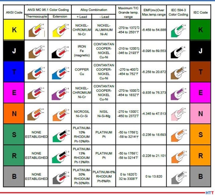
So, different types of thermocouples. Again, just a review question for us. Why use them? Why the different types and why are we using different types?
JN: Forgive me, Doug, and the rest of the audience, for that matter, if I end of repeating some of the things that came out in the previous episode. Basically, when you're talking about thermocouples, there are the two chemistries; for lack of a better term, you have “base” and “noble” metals. The base metals are really the metals that we focus on at Pelican. The noble metals are the more expensive ones- rare earth metals, tungsten, titanium, platinum and all those sorts of things that people spend exorbitant amounts of money on. There are purposes for those, but, typically, what you're going to see in the heat treat industry, in particular, you're going to see a lot of the base metals.
I like to say that, truly, the 20 gauge K, in particular, is the 800 pound gorilla in the room. It's almost considered, and I think it would be by people in the industry, a commodity. There are untold miles of that wire that are used in the heat treating and smelting industry. K is used, really, because of the temperature range. It fits in well with what people do in the heat treating industry. It is good for temperatures from zero up to around 1260 C. It's inexpensive, it covers the ranges that those people are looking for, and, again, it's the 800 pound gorilla in the room when it comes to temperature measurement in the heat treating industry.
Click to read the Heat Treat Today Original Content article on thermocouples.
The other types such as J comes up periodically, particularly if you're looking at lower temperature ranges. You won't see it quite as often in the heat treating industry. You will see it somewhat, but not to the degree that you would K. The J thermocouple wire has an iron leg so it does oxidize and you need to be careful about that sort of thing. Type T thermocouple wire has a narrower range. It has very good response times in cryogenic and cold temperature applications. The higher, upper end of type T thermocouple wire, typically, wouldn't be of terrible interest to the audience that we're involved with here, for the most part, because the upper ends around 370 to 400 C degrees, in lab environments; that's where it's going to be the most popular.
There is also type E. It's a higher temperature, as well. Response time. Broader range is a little bit better than K at lower temperature ranges. An interesting one is type N that you will see fairly often in the heat treating industry. For those people not familiar with type N, it is different alloys than type K. It covers virtually the same temperature range that type K does and will, actually, have less drift than type K. It is more expensive because of the alloys that it is made of, but, again, if you're interested in less drift, then type N is worth looking at. It hasn't quite caught on in the US the way it has in, say, Europe, in particular, and that really has to do with the infrastructure of the instrumentation. People have instrumentation that is either calibrated for K or J or something like that. Now, there is instrumentation out there, now, that would use K and N both, so we may see more, particularly, in the aerospace industry I would think it would become more and more popular.
DG: That's helpful. It's always good to hear those things over again.
How about the parameters and/or the factors that need to be considered when you're constructing the wire to start with? What do we need to be worried about in that area?
JN: I don't know if I like the word “worried” exactly, Doug. It's more, what do we need to think about? What do we need to be concerned about? Besides the metallurgy that we just talked about, we need to think in terms of what the sensor is actually going to look like. Is it just the wire? Thermocouple wire, by itself, can be a thermocouple; that's it, without any protection or anything like that.
As I mentioned earlier, you can tack weld it to an ingot, or something like that, and there you go. You don't have any probe, there is no thermal well to protect it or anything like that. But, what we do need to think about, then, is the process that it's going to be involved in. Where is it going to be used? Is it going to see an environment where there is a flow. Is it going to see an environment where somehow the thermocouple wire can become damaged? In that case, then, we're headed in the direction of talking about what our customers are interested in. And for a customer for Pelican Wire, we're mainly talking about people who actually assemble thermocouples – they make the connections, they have the molds and all that sort of thing.
To be clear, Pelican Wire just makes wire. And, again, the thermocouple wire can be used as a thermocouple, but a tremendous amount of wire is actually connected to some sort of a sensor or a probe, as I said, and is protected in a thermal well or something along those lines.
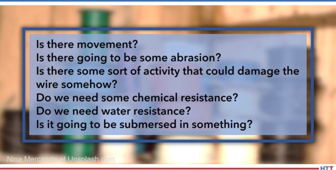
"But, what we do need to think about, then, is the process that it's going to be involved in. Where is it going to be used? Is it going to see an environment where there is a flow. Is it going to see an environment where somehow the thermocouple wire can become damaged? In that case, then, we're headed in the direction of talking about what our customers are interested in."
John Niggle
DG: Do we also have to be concerned with oxidizing, carburizing atmospheres, corrosive atmospheres? Is that, also, something that we need to be aware of?
JN: Absolutely. And that is one of the reasons you will see a probe thermocouple is because the wire is protected from that atmosphere. Nearly all of the wires that we talked about would be affected, particularly, in say, like a sulfurous environment; it would be subject to corrosion, oxidation and something along those lines.
Other factors, of course, are the accuracy and how much space we have. Believe it or not, if it's going to go into a small orifice, then we need to think about what the age size is going to look like. And then the environment: Is it going to be abrasive? Is there movement? Is there some sort of braiding motion that could wear a hole in the wire in the insulation and so forth? There are a lot of things to think about.
DG: And, it would probably be a good idea, especially if our heat treat people are running anything outside of the norm, regardless of what it is, whether it be atmosphere, configuration, fixturing, if there is anything outside the norm, they would probably be wise to mention it to the thermocouple wire and/or thermocouple probe manufacturer and make sure that they know so that you guys can get help get the right thing on there in their furnace.
JN: Yes, absolutely. At the end of the day, we work with this every day. We have design engineers on staff who can assist with technical questions and so forth and, of course, our customers, and the actual thermal wire assembly people, this is what they do every day of the week.
“I'll tell you that we've done some work, actually, in the aerospace industry and we had a customer that we sold significant, literally miles, of thermocouple wire to (when I say aerospace, it was specifically for space exploration) and this was because of whatever we had done with the insulation.”
DG: Let's talk about something a little bit new, I guess, to our conversation here in this 3-part series, and that is the insulation that's going to go around these wires. Can you tell us what are the different types of insulations and what are the advantages and/or disadvantages of each, and why would we be using them?
JN: I'll break it down into, what I would call, the four basic categories. That would be an extruded insulation, insulations that are tapes, fiberglass insulations that are routinely worked with and then, of course, high temp textiles. High temp textiles, in particular, would be of interest to the audience here in the heat treat metallurgy world.
Extruded insulations can be a variety of thermoplastics. A term that, I think, Ed has probably mentioned before and we've talked about before is extension grade wire. That typically has a PVC insulation on it and the reason PVC works for that is that it's cheap and extension grade wire, typically, does not see the sorts of high temp environments that you're going to see in processes. It's really a signal wire that takes the signal from the probe or from the sensor to the process control device.
DG: So what kind of temperature tolerances can the extruded wire handle? Are we talking 300, 400 degrees? I guess you talk C, I talk F.
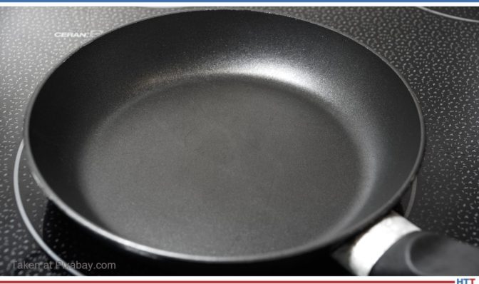
Teflon frying pan
JN: We talk whatever language our customer likes to talk, but we do talk C quite a bit. So, PVC is quite low, it's in the 200s F. But, when you're looking at fluoropolymer insulations (and Pelican is really a high temp house, so we focus on the higher temp insulations) you have FEP and PFA, those are in the 200s. PFA actually goes up to 260. So, you can see, it's probably not suitable for heat treating applications, smelting and that sort of thing. The advantages to those compounds would be that you're going to have abrasion resistance. Think about your Teflon frying pan: it's slick, it's smooth. So, if you're in an environment where there is some movement, it will be good for that. And, of course, it will have excellent moisture resistance and chemical resistance. Those would be the advantages to the extruded wire. The other advantage would be, because you'll have a thinner wall than you will with the other insulations, you'll have some more flexibility. So, if you have a type N radius, you can go around a corner easily.
The next step up, in terms of temperature resistance, would be the tapes. Basically, in that area, you're looking at PTFE tape, mica take and capped-on tape or polyamide tape. Those will give you slightly higher heat resistances. The mica, in particular, would give you more. (Mica, as a matter of fact, is used as a supplement to the PTFE to give it even higher heat resistance.) Mica will go up to 500 C, PTFE and the polyamides match, in terms of heat resistance, the extruder products around 260. What they do give you, again if you use the tapes, is the heat resistance you're looking for, some abrasion resistance and the moisture resistance. You'll have less flexibility because those products are stiffer, but they're also going to be a little bit lighter weight unless you incorporate the mica into it. Then, when you do that, you're going to end up with an even stiffer wire and it will be a little bit heavier, and all those will be larger in diameter than an extruded wire. If you look at an environment where you need to poke the wire through a hole and that hole is an eighth of an inch, you need to think really hard if what you're doing is going to work.
DG: So you've got extruded and you've got tapes.
JN: The next step after that would be fiberglass. In the case of fiberglass, you have E glass and S glass. Of the two, E glass would have the lower temperature resistance and you're looking at 482 C on the high end. For S glass, you're up to 704 C. Now you're starting to talk about insulations that you will see in the heat treat environment; it's quite common, especially on the S glass side where you're looking at the 704, you'll see a lot of people that need 500 C for whatever reason. The advantage, obviously, to the glass, as I mentioned, is the higher heat resistance.
There are disadvantages. Think about fiberglass for a minute. We actually have to saturate the wire to keep it from fraying without it ever really experiencing any abuse. If we don't saturate it, then the wire can fray, and you can get fiberglass in your fingers even, which is unpleasant. So, fiberglass has some disadvantages like that. If you put it in an environment where there is some movement, abrasion, vibration or something like that, it can be problematic. Also, it's going to be stiffer because it's saturated, typically. Sometimes you'll even see those saturants even cause problems in a heat treat environment where, if it gets too hot, the saturant can leave an ash behind. You're going to lose flexibility, as I said. You're not going to have the abrasion resistance, the chemical resistance or the moisture resistance that you're going to get from an extruded product.
The other one that we see, again, literally miles and miles and miles of, in the heat treat world would be what's called Refrosil and Nextel, (those are both, actually, trade names). We're talking about vitreous silica and ceramic. Again, those are, what we call, high temp textiles. Now, you're looking at products that are in the 1200 C range. Ceramic goes up to 1204, vitreous silica is in the 870's. Again, there are some of the same disadvantages with those that you're going to have with glass. It's going to be somewhat fragile. We don't saturate those because the saturants are not going to hold up in the environments that they're going to be placed into, so you would have that ash residue left.
Again, it will be stiff, it will be even larger in diameter than the fiberglass, which is larger than tape which is larger than the extruder products. Of course, you're not going to have the abrasion resistance, the moisture resistance or the chemical resistance. But it does protect the wire in those elevated temperature environments that are critical for the heat treating industry.
DG: Let's back up a bit. I want to understand something you said. You said, in the fiberglass, it is saturated and in the textiles it's not. I want to know what you mean by saturated.
JN: It's either a solvent-based or a water-based saturant that is applied to the wire to protect it. Think in terms of a varnish. It would be like a protective coating. Again, it just keeps the exterior of the wire, the bare wire, from being exposed. It's a coating, but we call it a saturant.
DG: High temperature textiles tend to be the stuff we're using, in the heat treat industry, probably most.
JN: Yes. Again, when I mentioned the 800 pound gorilla in the room, the 20-gauge K with the vitreous silica or the Refrosil would be an extremely popular product in the heat treating industry, absolutely.
DG: Let me ask you a very, very fundamental question. I'm curious of your answer to this. Why do we insulate wires at all? Is it done to protect from temperature or is it done simply to protect them from crossing with each other and grounding or shorting out? Why do we insulate?
"I'll go back to something that I know Ed talked about: the Seebeck effect. You have this loop; if you don't have that loop, then you don't have anything. You don't have the EMF, the electromotive force, that you're looking for."
John Niggle
JN: It is the second part. When you look at any wire construction, the two singles have to be insulated from each other. I'll go back to something that I know Ed talked about: the Seebeck effect. You have this loop; if you don't have that loop, then you don't have anything. You don't have the EMF, the electromotive force, that you're looking for. We do make a wire that is not duplex, but, typically, what you're going to see is a wire that has two singles and then it's duplexed with an insulation over the top. We do make a wire that the two singles are jacketed in parallel and then no jacket is placed over the top but that is for an application that wouldn't be suitable for the heat treat industry.
DG: I asked that question, because for those who are unbaptized in this conversation, it's kind of interesting. So, we're talking about insulation and we're doing a lot of conversation about temperature ranges and, for someone who wouldn't think so, they would say, "Well, that means you're insulating because of temperature." But, really, the reason you're insulating wire is for electrical. It's to keep them apart. It's just how high of temperatures those insulations can handle, not that you're insulating the wire to keep them cool. Right?
JN: Absolutely not.
DG: That may sound very basic, but there may be people that think that, so I want to get that on the table.
JN: Most of the people in the audience are probably familiar with this already. Typically, what happens is the wire is stripped so we have exposed ends. And then those ends, as we mentioned earlier, can be tack welded onto something or they can just be out there. The thermocouple world, by the way, is an incestuous world where we have customers, we kind of compete with those customers, some of our customers compete with others of our customers but then they buy supplies from each other. You probably already know that from talking with other people in this industry. At any rate, the wire is stripped and then it's either tack welded or it's connected to some sort of sensor or probe of some kind.
DG: It's a tangled web, the whole thermocouple world. You've got customers, yet you sell to certain suppliers who also sell to those customers. It can be complicated! But that's OK, we'll let you guys worry about that; we just want to make sure the thermocouples are good and we'll be in good shape.
Another question for you: We talked about the process and a lot of different environments about what type of thermocouple you should use, but does the process being monitored influence the type of insulation that should be used? Obviously, temperature is going to have an impact, but is there anything else?
JN: Yes. Let's circle back to what we talked about earlier just a little bit. When you look at the process, you need to think of what is going to happen to that wire? Is it going to see, first of all as you mentioned, the temperatures? That is certainly important so that comes into play with the insulation. But, we need to think about, Is there movement? Is there going to be some abrasion? Is there some sort of activity that could damage the wire somehow? Then, we need to look at the chemicals, like we talked about. Do we need some chemical resistance? Do we need water resistance? Is it going to be submersed in something? Those things all need to be considered.
Again, as I mentioned earlier, the actual placement of the wire. Does it need to be inserted in a hole? At Pelican, we produce wire down to 40 and actually 44 gauge which, I think, will probably be stunning to most of the people in your audience because, again, 20-gauge K is what these people think about. In the heat treating industry, what you see is they need a robust wire, something that's going to be able to handle those temperatures and a large conductor like that.
Another thing to think about, actually, is a bend radius. Are you going to put the wire somewhere where it needs to go around a corner, around a bend? Then, are you better off using a stranded wire? A stranded wire is going to have more flexibility. You can buy a 20-gauge stranded wire, you can buy 24-gauge, 28-gauge, 36-gauge.
DG: Now, what do you mean by stranded?
JN: Stranded wire would be instead of just one solid 20-gauge conductor, you have multiple strands that make up that 20-gauge. But, if you think about it, multiple strands of wire will actually be more flexible. You'll still get the same results, but it will be more flexible if you need to go around a corner or if you need to insert it into something.
DG: It's almost like a braided wire as opposed to a solid.
JN: Yes. Now braiding is a little bit of a different process. When we're talking about stranded wire, it's, basically, just spiral. Braided is more crossed into each other, which, coincidentally, is the way that the fiberglass and the high temp textile insulations are made – those are actually braided. And, by the way, I'll just toss this out, it's made on equipment that really hasn't changed since the ‘20s. I'm not talking about the 2020s, I'm talking about the 1920s! Rumor has it, some of that braiding equipment was, actually, designed by Thomas Edison. I'm not sure if that's really true. But that is the process used to apply the fiberglass and high temp textiles.
DG: So, anything else as far as any other considerations we need to take into consideration when we're talking about choosing insulation? If not, that's fine.
JN: I think I covered them, Doug.
DG: At Pelican Wire, your company, I know you guys deal with a broad number of markets, I'm sure, one of them being heat treat. What do you see as any special demands or special concerns that are, maybe, unique or, at least, inherent in the heat treat market?
". . . what you see is insulations that are higher in temperature resistance, as well. In some cases, as I mentioned earlier, in ovens where there is a saturant involved, we could see ash. Some people ask that saturant not be applied to the fiberglass and that's certainly something that can be done."
John Niggle
JN: For the heat treat market, again, I'll go back to what I said earlier, we see a lot of 20-gauge K used. It's because of the higher heat requirements, the higher heat that is involved with the processes of heat treating. Secondly, what you see is insulations that are higher in temperature resistance, as well. In some cases, as I mentioned earlier, in ovens where there is a saturant involved, we could see ash. Some people ask that saturant not be applied to the fiberglass and that's certainly something that can be done.
Sometimes we're even asked to not put tracers. We go back to what we talked about earlier with the metallurgy- you have two legs, a positive and a negative leg. Well, how do those end users tell those legs apart if they look similar, if they're an alloy of some kind? So, we put a tracer wire in there so you have a red leg and a yellow leg, in the case of type K, or sometimes you just have a red leg depending on what they ask for. Those tracers can, actually, cause problems, too, if the ovens are hot enough and they are in there for long enough times. We even have customers who ask us not to put tracers in their wire, for that matter.
Accuracy, of course, is extremely important. I know that Ed, in a previous episode, talked about standard limits, special limits and all that sort of thing. Typically, you're going to see special limits used in the heat treat industry and, in some cases, we're asked even for special calibration points. In previous podcasts, I've heard you talk with other people about AMS2750 and how that comes into play. It is extremely critical for the folks in the heat treating industry and something that clearly a thermocouple wire producer has to understand.
Episode 1 of 3 of AMS2750 series
DG: Let's say you've got a customer that calls you and wants to talk about their thermocouple needs, let's say there is some sort of special need. What would you suggest they have, in hand, when they call you? What do you need to know from them to help you do a better job with their thermocouple needs?
JN: Honestly, the first question we do ask is: What temperature are you going to be running this at? How hot are we going to be? We, absolutely, need to know that. That helps us narrow down the alloy that we might be looking at, whether it's type K, type J, type E, or whatever. And then, of course, it's a natural thing to dial in the insulation after that. Quite honestly, one of the things that frustrates me is when people say, "I need Teflon." Well, OK. Do you need FEP or do you need PFA? Those are both fluoropolymers like Teflon is. We need to talk about temperature resistance, so don't tell me you just need Teflon. We do need some specifics when it comes to that sort of thing. Again, we talked earlier about stranding and stranded wire. Do you need some flexibility? What gauge size do you think you need? How robust does this wire need to be? Those are some of the key factors we need to know about.
DG: Let's say, for example, somebody does want to get a hold of you or Ed, your colleague who was on the first two episodes, how is best to do that? How can we get a hold of Pelican Wire?
JN: Our web address is www.pelicanwire.com, about a simple as it possibly gets. Our email addresses are, actually, quite simple, as well. If anybody wants to email me, it's jniggle@pelicanwire.com. You can contact me directly, if you want to, or we have a sales inbox and that is simply sales@pelicanwire.com. We do have a phone number, but it seems a lot of people don't care about phone numbers as much these days. But the number is 239-597-8555.
DG: I have one, unrelated, question for you that I know the world is wanting to know: How is it having a company in Naples, Florida, that's what I want to know?
JN: I'll tell you what, Doug, the answer today will be different than the answer in October or December. It's actually quite nice. We moved down here 8 years ago in 2013. I moved from the Midwest and didn't really feature myself owning palm trees, but I own palm trees, which is pretty darn cool. We are, as the crow flies, about 3 miles from the water, where I live anyhow, 20 minutes by car. Our office and manufacturing facility are, actually, on the very edge of the everglades. You can see the picture in the background behind me. That's our building. That's actually facing east. That is a sunrise over the everglades. We're on the very edge of the everglades. There is a lake right next to our building and then, after that, it's everglades all the way over to Miami. And, real quick, our weather pattern comes from the east. It doesn't come from the Gulf. This time of year, in the summer at about 3:00 in the afternoon, about the time that we're doing this call right now, a thunderstorm blows up and it comes from the east over the everglades and it moves to the west. The trees blow that direction, you can see it coming. It's interesting. During the wintertime, I have to tell everyone, you'd probably be jealous, but it is truly paradise.
DG: Yes! I've been to Naples, ate at a nice restaurant down there, years ago, but it was very nice.
You guys are also employee-owned, right?
JN: That's correct, yes. The company is over 50 years old. The founder of the company passed away in 2008 and, before he passed away, he converted the company to an employee-owned operation. So, we've been employee-owned since 2008. We've purchased a couple other companies since then that folded into, what we call, the Wire Experts Group. Pelican Wire is part of that. We have a sister company out in Colorado. We bought another facility in Chicago and folded that into our company in Colorado. So, yes, we're employee-owned and it works out really well for the employee owners, I'll tell you that much.
DG: That's great. John, it's been a pleasure talking with you. Thanks for taking the time. I appreciate your expertise. Hopefully, we will see you out on the pavement somewhere in the real world.
JN: I'll, actually, be seeing you at the heat treat show in about 3 weeks.
DG: That's about right, yes.
JN: Hopefully, some of the people that are listening we will see, as well.
Doug Glenn
Publisher Heat TreatToday
To find other Heat Treat Radio episodes, go to www.heattreattoday.com/radio and look in the list of Heat Treat Radio episodes listed.
An aeronautic motion control manufacturer invested in a low-temperature vacuum furnace. The furnace operates up to 1380°F (750°C) with work zone dimensions of 24” x 24” x 36” and a load capacity 1750 lb. The furnace works for applications with process temperatures up to 1400°F and where product surface purity is required.
Piotr Zawistowski Managing Director SECO/VACUUM TECHNOLOGIES, USA
The SECO/VACUUM Technologies furnace meets class 2 TUS requirements per AMS2750F - +/-10°F and is capable of nitrogen convection heating and cooling. The furnace can realize low-temperature processes under vacuum and in nitrogen convection. Cooling – the final stage of every heat treat cycle – is completed using an internal recirculation blower and an internal, water-cooled heat exchanger. In addition, the furnace has built-in software tools for monitoring and control.
“The type of heat treat equipment this customer has acquired from us demonstrates a significant bandwidth in our capability to meet a wide range of thermal processing needs," Piotr Zawistowski, managing director of SECO/VACUUM says. "We find this is fairly typical of aircraft OEMs and suppliers since the demands on their complex product range are not easily satisfied by a 'one-size-fits-all' solution.”
This is the fifth vacuum furnace for tempering, aging, and other processes supplied by SECO/WARWICK Group to the international aircraft controls manufacturer.
A Dutch manufacturer and global heat treater has reached a definitive agreement to acquire 100% of the shares of Premier Thermal Solutions LLC (PT), based in Lansing (Michigan, USA). PT operates nine locations across the industrial Midwest in Michigan, Wisconsin, Indiana and Ohio, and provides surface technologies and related services to achieve metallurgical specifications for its various industrial clients.
Their specialized technology portfolio in the industrial Midwest region of the U.S. will complement Aalberts N.V. surface technologies, which has core activities in the Northeast and Southeast region. PT is serving the light and heavy truck, electrical vehicles, agriculture, defense and aerospace end markets.
PT has a project funnel that includes work in electrical vehicles, light and heavy truck, agriculture and industrial end markets. NADCAP and OEM certifications allow Aalberts surface technologies to progress work in the defense and aerospace markets in North America.
The management team of PT, under the leadership of Steven Wyatt, will continue to develop the business and drive business opportunities.