This article continues the ongoing discussion on Equipment Selection for Induction Hardening by Dr. Valery Rudnev, FASM, IFHTSE Fellow. Six previous installments in Dr. Rudnev’s series on equipment selection addressed selected aspects of scan hardening and continuous/progressive hardening systems. This post continues a discussion on equipment selection for induction hardening focusing on single-shot hardening systems.
The first part on equipment selection for continuous and progressive hardening is here. The second part in this series on equipment selection for single-shot hardening is here; the third part is here. To see the earlier articles in the Induction Hardening series at Heat Treat Today as well as other news about Dr. Rudnev, click here. This installment continues a discussion on equipment selection for continuous and progressive hardening applications.
Why Single-Shot Hardening?
With the single-shot method, neither the workpiece (cylinder shaft, for example) nor the coil moves linearly relative to each other; the part typically rotates instead.¹ The entire region that is to be hardened is heated all at once rather than only a short distance, as is done with scan hardening.
With conventional scan hardening of cylindrical parts, induced eddy currents flow circumferentially. In contrast, a single-shot inductor induces eddy currents that primarily flow along the length of the part. An exception to this rule would be the half-moon regions (also called the crossover or bridge sections) of a single-shot inductor, where eddy current flow is circumferential.
Normally the single-shot method is better suited for hardening stepped parts where a relatively short (1.5–2 in. [38–50mm] long heated area is commonly minimum) or moderate length area is to be heat treated. This method is also better suited to cylindrical parts having axial symmetry and complex geometry including various diameters.
When scanning these types of parts, improper austenitization of certain areas may occur due to localized electromagnetic field distortion, for example. Insufficient quenching due to the deflection of quench flow not allowing it to properly impinge on the surface in various diameter regions may also occur. Both factors are considered undesirable and can cause low hardness, spotted hardness, or even cracking. For example, the use of scan hardening on stepped shafts with large shoulders, multiple and sizable diameter changes, and other geometrical irregularities and discontinuities (including fillets, flanges, undercuts, grooves, etc.) may produce severely non-uniform hardened patterns. In cases like this, a scan hardening inductor or progressive/continuous hardening system would be designed around the largest diameter that would have sufficient clearance for safe part processing.¹ However, variations in the shaft’s diameter, to a significant extent, will result in a corresponding substantial deviation in the workpiece-to-coil coupling in different sections of the shaft, potentially causing irregular austenization.
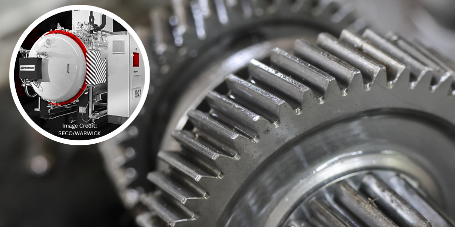
Besides that, sharp corners have a distinct tendency to overheat owing to the buildup of eddy currents, in particular when medium and high frequencies are used. The electromagnetic end and edge effects may also cause the shoulders to severely overheat while the smaller-diameter area near the shoulder (including undercuts and fillets) may have noticeable heat deficit. These factors may produce a hardness pattern that might grossly exceed the required minimum and maximum case depth range, making it unacceptable. Single-shot hardening is usually a better choice in such applications. As an example, Figure 1 shows some examples of components for which single-shot hardening would be a preferable method of heat treating.

In some not so frequent cases, when hardening larger parts, there are advantages to the single-shot method over the scanning method, such as the reduction of shape/size distortion, enhanced metallurgical quality, and increased production rate.
Single-shot hardening may also be the preferred choice when shorter heat times/high production rates are desired. For example, in some applications, the time of heating for single-shot hardening can be as short as 2 s, though 4 to 8 s is more typical.
However, the single-shot method has some limitations as well. One of them is cost. Single-shot inductors are typically more expensive to fabricate compared to the coils used for scanning. This is because the single-shot inductor, to some degree, must follow the contour of the entire region required to be heated. Additionally, a single-shot inductor is usually able to harden only one specific part configuration, whereas a coil used for scanning may be able to harden a family of parts.
Besides that, in some case hardening applications using a scanning method, it is possible to apply certain pre-programmed pressure/force on a workpiece during heat treating. This allows distortion to be controlled. Single-shot hardening might also permit applying this technique but there might be some limitations.
Design Features of Single-Shot Inductors
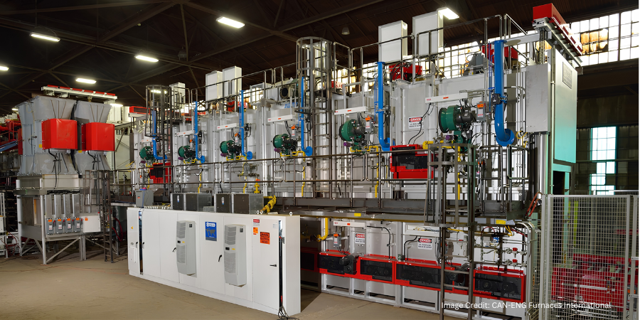
Single-shot inductors are made of tubing, either 3-D printed or CNC-machined from solid copper to conform to the area of the part to be heated. This type of inductor requires the most care in fabrication because it usually has an intricate design and operates at high power densities, and the workpiece’s positioning is critical with respect to the coil copper profiling. Figure 2 shows several examples of induction heating of different components using single-shot inductors.

In order to provide the required temperature distribution before quenching, heat is sometimes applied in several short bursts (pulse heating) with a timed delay/soaking between them to allow for thermal conduction toward the areas that might be difficult to heat.
Single-shot inductors typically require higher power levels than used in scan hardening because the entire area of the workpiece that needs to be hardened is austenitized at once. This is the reason why single-shot hardening normally requires having a noticeably larger power supply compared to scan hardening, resulting in increased capital cost of power source. Additionally, the increased power usage and power densities combined with complex geometry can reduce the life of the inductor. For this reason, single-shot inductors often have shorter lives than scan inductors.
It is always important to keep in mind that, electrically speaking, the inductor is typically considered the weakest link in an induction system. For this reason, most single-shot inductors have separate coil-cooling and part-quenching circuits. The inductor will fail if power is increased to the point at which the water cannot adequately cool it. Additional cooling passages may be needed with high-power density, single-shot inductors. A high-pressure booster pump is also frequently required.
The next several installments of Dr. Valery Rudnev on . . . will continue the discussion on design features of single-shot inductors and equipment selection.
References
- Rudnev, D.Loveless, R.Cook, Handbook of Induction Heating, 2nd Edition, CRC Press, 2017.