One of the leading global power, aviation and renewable energy providers has selected a vacuum furnace hot zone replacement. The replacement and modernization of this hot zone is to be updated in a 20+ year old furnace. Once the furnace is updated, it will be installed at the client's facility in Hungary, Europe.
The supplier, SECO/WARWICK, replaced the hot zone of a horizontal vacuum furnace so that it could be integrated with the new, technologically advanced materials in the industry.
CQI-9 compliance demands adherence to the standards for the purpose of excellence in automotive heat treating. Poorly maintained quench oil can cost heat treaters in many areas.
In this Heat TreatToday Technical Tuesday feature, Greg Steiger, senior key account manager at Idemitsu Lubricants America, shares how costly quench oil issues can be addressed through proper adherence to the CQI-9 quench oil testing protocols. Let us know if you’d like to see more Original Content features by emailing editor@heattreattoday.com.
Greg Steiger Sr. Key Account Manager Idemitsu Lubricants America
Introduction
A poorly maintained quench oil can cost a heat treater in more ways than simply the cost of having to replace the oil. The costs can quickly expand to include those associated with poor quality. For example, costs associated with part rejects, or rework and downstream costs for shot blasting, or third-party inspection are often the cause of poor quench oil maintenance. Dirty or poorly maintained oils can affect part cleanliness, surface hardness, and surface finish. For instance, it is well known that a heavily oxidized oil may create surface stains that must be shot blasted to remove. High molecular weight sludge or excessive water can create surface hardness issues. Many of these issues can be addressed through proper adherence to the quench oil testing protocols established by CQI-9.
How can CQI-9 help?
CQI-9 is designed as a tool to help heat treaters produce consistent parts. Using a CQI-9 compliant quench oil analysis can also be a very powerful tool in a heat treaters tool kit. Just as the level of carburization is influenced by the carbon potential of a carburizing atmosphere, the cooling speed of the oil influences microstructure formation and microstructure composition along with mechanical properties such as hardness as well as tensile and yield strength. Furthermore, the cooling speed is dependent upon the viscosity of the oil, the amount of sludge, moisture level, and oxidation of the oil. All of these are tested on a regular basis under the requirements of CQI-9, ISO TS 16949, and most quality systems adopted by modern heat treaters. All of the tested parameters required under CQI-9 will be addressed individually later in this paper.
What is CQI-9?
The member companies of the Automotive Industry Action Group (AIAG) encompassing automotive manufacturers and their Tier I suppliers have enacted an industry heat treating standard called CQI-91. This standard was originally a standalone standard designed and adhered to primarily by North American OEMs and Tier I suppliers as a quality tool to create consistent documented processes within the heat treating industry with the goal of producing consistent reproducible results. Since that first implementation of CQI-9, the standard has now been incorporated into the ISO TS 16949 standard and is now adhered to by most automotive OEMs and their Tier I suppliers. The full range of management responsibilities, material handling, and equipment operations of the CQI-9 standard is beyond the scope of this paper. Instead we will be discussing the used quench oil analysis requirements of CQI-9, why the tests are required, and how heat treaters need a CQI-9 compliant quench oil analysis to properly care for their quench oils.
Utilizing a compliant CQI-9 analysis and the supplier provided operating parameters for the CQI-9 required tests is the first step in the proper care of a quench oil.
CQI-9 Compliant Analysis
Most quench oil suppliers provide a quench oil analysis. Although the quench oil supplier may provide a quench oil analysis, for the analysis to be CQI-9 compliant the analysis must contain the following tests or their equivalent:
Water content; ASTM D6304
Suspended solids; ASTM D4055
Viscosity; ILASD509
Total acid value; ASTM D664
Flash point; ASTM D92
Cooling curve; JIS K2242
The frequency of the above testing must be a minimum of semiannually. A more frequent sampling interval does not violate CQI-9. In fact, the more often a quench oil is analyzed, the easier it is to use the quench oil analysis as a tool in the proper care of a quench oil. It is important to note that the CQI-9 standard does not prescribe specific test methods be used in the above testing; however, they must be performed to a traceable standard. The CQI-9 standard only states that the above values, along with a cooling curve, must be reported. The following sections will describe each test in a CQI-9 compliant analysis.
Water Content
Everyone knows water in a quench oil can be have catastrophic safety and performance consequences. However how much water is too much? That is a question that is difficult to answer. The answer depends on a variety of factors such as the quench oil used and all of the variables associated with a furnace atmosphere. A general rule of thumb when it comes to water levels is to keep the water level below 200PPM. At levels above 200PPM of water, uneven cooling begins to occur.2 It is important to remember a quench oil is not a pure homogenous fluid. Samples taken at various places throughout the quench tank will be similar but will also have differences. These differences will include water and solids levels. Therefore, in areas where the water content exceeds the 200PPM level, uneven cooling will begin. Parts coming into contact with this “localized” quench oil with high water can potentially begin to crack, have a high surface hardness, or have staining problems. Yet parts in other areas of the load continue to behave normally. For this reason, and also because water is much heavier than oil, it is imperative the oil be under agitation. In addition to the potential uneven cooling issues high water may create, a high level of water can also influence the rate of oxidation in an oil.
Suspended Solids
Because solids are typically denser and more viscous than liquids they do not have the same heat transfer properties as a liquid. Due to the inequality of heat transfer capacities between liquids and solids, it is very important to keep the solids level, especially high molecular weight sludge, at a minimum. Sludge reacts in an opposite manner of water. Where water can increase quench speed, high molecular weight sludge will decrease quench speed through uneven cooling.2 The result of the uneven cooling from sludge is typically seen in soft surface microstructures or soft surface hardness. Also, like water, sludge is heavier than oil and the lack of homogeneity in the oil means having proper agitation is paramount when sampling.
Viscosity
Changes in viscosity can lead to both faster quench rates and slower quench rates. As the quench oil is used in the quench process, it undergoes thermal degradation.3 This degradation process can be seen when the oil becomes thinner or less viscous. During this process, a small portion of the base oil and a small amount of the quench oil additives undergo a process called thermal cracking. In this process, heavier molecules are broken into smaller molecules through the use of heat. This thermal cracking creates lighter less viscous oil from heavier oils. The newer lighter viscosity of the quench oil can potentially lead to changes in the quench speed of the oil. These changes can have an impact on the microstructure, case depth, core hardness, and surface hardness on the quenched parts.
As an oil is subjected to the high temperatures of a quenching operation, oxidation is a natural occurrence in the oil. As the oil oxidizes it will begin to increase in viscosity until it reaches the point of forming an insoluble sludge. Therefore, an increase in viscosity typically means the oil is oxidizing. Just as an oil that becomes thinner and less viscous may have a change in cooling properties, an oil that becomes thicker and more viscous may see a change in cooling performance. A thicker oxidized quench oil may affect surface hardness, microstructure, case depth, and core hardness. In severe cases of oxidation staining may result. Such stains typically require post quench and temper processing such as shot blasting.
Total Acid Value
The Total Acid Value, or TAV, is a measure of the level of oxidation in a quench oil. The amount of oxygen in a quench oil cannot be measured without a sophisticated laboratory analysis. However, the formation of organic acids within a quench oil can be easily determined via a titration method. It is well understood that these organic acids are the precursors in a chain of chemical reactions that will eventually form sludge. As the TAV increases so will the levels of oxidation, and in turn, the amount of sludge will also increase. Consequently, as the TAV increases, the amount of staining due to oxidation may increase. The cooling properties of the oil may decrease due to the increased sludge formation as well. Figure #1 shows an example of how the acid value increases the viscosity of a quench oil due to the formation of polymeric sludge in the quench oil.2
Figure #1. Acid number vs kinematic viscosity for Daphne Hi Temp A
Flash point
The flash point of a quench oil is another check to ensure the safety of the quench oil user. As oil thermally cracks, the heavier base oils become not only lighter in viscosity, but their flash points also decrease. If left unchecked, the decrease in flash point could result in a higher risk of fire. In addition to serving as a watchdog against the results of excessive thermal cracking, a flash point is also a safeguard against human error and adding the wrong quench oil to a quench tank. High temperature oils typically have a higher flash point than conventional oils. An increase in flash point, along with no change in TAV, and an increase in viscosity could indicate a contamination issue between oils has occurred.
Cooling curve
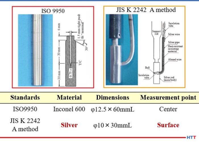
There are many different methods of running a cooling curve. Many Asian suppliers of quench oil will use the Japanese Industrial Standard (JIS) K 2242. European suppliers will use the ISO 9950 and North American suppliers rely on the ASTM D 6200 method. All of these standards measure the same basic property, the ability of an oil to reach martensite formation. However, they differ in one basic item. The JIS K-2242 and methods used in China and France use a 99.99% silver probe that is smaller than the size of the Inconel probe used in the ASTM and ISO methods of Europe and North America. Because of this difference, it is important to note that cooling curves and cooling rates between the methods should not be compared. Figure # 2 shows the comparison between the two probes and their dimensions.
Figure # 2. ASTM D-6200/ ISO- 9950 and JIS K 2242 quenchometer probes^2 ISO/ASTM Inconel probe 12.5mm x 60mm. JIS K 2242 Silver probe 10mm x 30 mm
In addition to comparing the cooling curve against the standard for the quench oil used, the Grossman H value should also be calculated and used as an indicator of cooling performance. Unlike the old GM nickel ball test that tracked the time to cool a 12mm nickel ball to 352°C, the Grossman H value measures the severity of the quench6.
In using the Grossman H value, the lower the value, the slower and less severe the quench. For use as a rough guide in comparing the quench speed in seconds to the Grossman H value measured in cm-1 the table below can be used.
Table #1
For example, air has an approximate H value of 0.01 cm-1 and water has an approximate H value of 0.4 cm-1 compared to oil with an approximate H value of ___ cm-1
The calculation used to determine the Grossman H factor has historically been:
H=h/2k
Where h is the heat transfer coefficient of the part when measured at the surface of the part and k is the thermal conductivity of the steel. Typically the heat transfer coefficient is measured at 705°C. A steel’s thermal conductivity does not typically change according to alloy composition or temperature. Therefore, the Grossman H value is proportional to the heat transfer coefficient of the part.
Interpreting a CQI-9 quench oil analysis
Table #2
Discussion
In examining the test parameters for CQI-9, it becomes apparent that many of the test results should be compared with other test results. For example an increase in the amount of sludge or solids should also increase the viscosity of the quench oil. As the sludge increases, the level of oxidation increases, and therefore, the level of organic acids formed in the quench oil should be increasing the TAV. Finally, as the sludge increases, the cooling property of the quench oil should decline as indicated in the lower H value.
Figure #3. Total Acid Value (TAV) and Grossman H value
Likewise, as the flash point decreases the amount of thermal cracking is increasing, which should reduce the viscosity and thereby increase the H value and the overall cooling speed of the quench oil. Conversely, if the test parameters are not working in concert with each other, there may be other issues going on within the quench oil. For instance, an increase in the water content can be detected before the increased water levels begin the oxidation process thereby increasing the TAV. Or a viscosity change without a change in other parameters could be an addition of the wrong quench oil to the quench tank. The graph below for Idemitsu Daphne Hi Temp A helps illustrate this point.
Figure #4. Graph for Idemitsu Daphne Hi Temp A demonstrating viscosity change
In the graph above, it can be seen when the water H value increases and the viscosity remains stable, the likely explanation is an increase in water. When both the H value and viscosity decrease, additive consumption is the most likely reason. Likewise, when the viscosity increases and the H value decreases, the formation of sludge from oxidation is the culprit.
Having test parameters that work in conjunction with each other is only beneficial if sample frequencies are often enough. While CQI-9 only stipulates a semi-annual sampling frequency, the conditions of a quench tank can change in very short order. There are the obvious changes when water is added to the tank. However, many of the changes are more subtle, and left unchecked over time can create potential costly solutions such as a partial dump and recharge of the quench tank, poor part quality, or an increase in downstream processing such as shot blasting. For this reason, many quench oil suppliers request a minimum of quarterly sampling. In addition, if a sample is missed on a quarterly sample frequency, there is still time to sample the quench tank and remain in compliance with CQI-9.
Conclusion
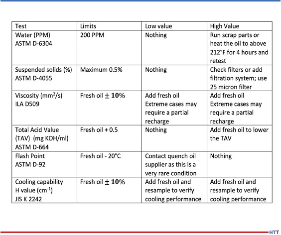
Over time the condition of a quench oil will change and corrective measures will be needed to bring the quench oil back into the suggested supplier’s operating parameters. The chart below helps understand what some of the methods need to be.
With proper care and maintenance, a quench oil can last a very long time. A conventional oil should last 10 to 15 years or longer while a marquench oil should last seven to 10 years. The proper care of a quench is simple and straight forward. A quality quench oil should not need the use of additives to improve oxidation resistance or quench speed. Simply adding enough fresh virgin oil to replace the oil that is being dragged out through normal operations should replenish the oxidation protection and quench speed to within the normal operating parameters. The table below offers recommendations for treating out of normal operating parameters for the required CQI-9 tests.
Recommendations for treating out of normal operating parameters for the required CQI-9 tests
Most heat treaters make weekly quench oil additions to their quench tanks. The most popular type of filtration system is a kidney loop style where the quench oil is constantly filtered. There are two basic types of these systems. They differ in the number of filters used. For a single filter system, a 25 micron filter is sufficient for quench oil filtration. In a two-stage filtration system, a 50 micron filter is typically used in the first stage and a 25 micron filter is used in the second stage. In a two-stage filter, the cheaper 50 micron filter will be replaced more often than the 25 micron filter in the second stage.
Utilizing a compliant CQI-9 analysis and the supplier provided operating parameters for the CQI-9 required tests is the first step in the proper care of a quench oil. The next basic steps are ensuring there is enough fresh quench oil available for regular additions to replace the oil that is lost through drag out and proper filtration of the quench oil in a constant kidney loop type of a system. With these steps in place, a quench oil will offer consistent performance for years and will be one less concern heat treaters face in the operation of their furnaces.
References:
Automotive Industry Action Group, “CQI9 “Special Process: Heat Treatment System Assessment;” AIAG version 3, 10/2011.
M.A. Grossman and M. Asimov. Hardenability and Quenching. 1940 Iron Age Vol. 107 No.17 Pp 25-29.
About the Author:
Greg Steiger is the senior key account manager of Idemitsu Lubricants America for quench products. Previous to this position, Steiger served in a variety of technical service, research and development, and sales marketing roles for Chemtool, Inc., Witco Chemical Company, Inc., D.A. Stuart Company, and Safety-Kleen, Inc. He obtained a BSc in Chemistry from the University of Illinois at Chicago and is currently pursuing a Master’s Degree in Materials Engineering at Auburn University. He is also a member of ASM International.
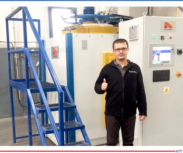
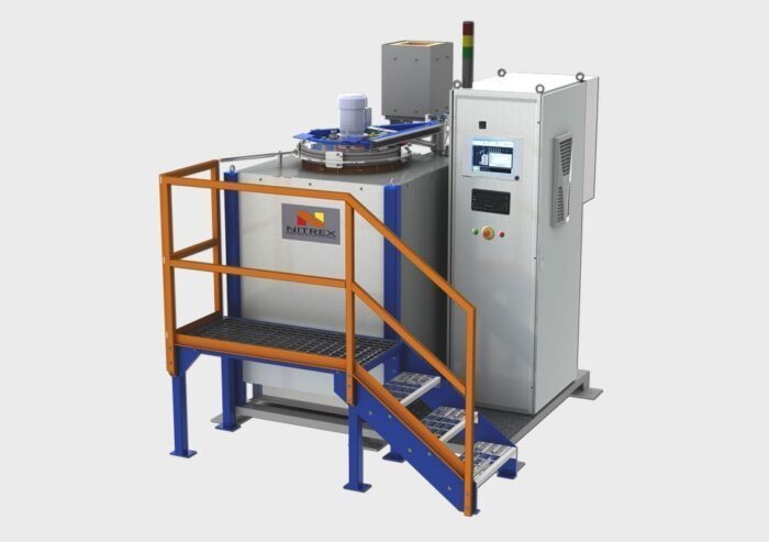
Alugen Aluminium, a Turkish aluminum extrusion company, recently expanded their production capabilities with a high-performance compact nitriding/nitrocarburizing system. This system will allow the company to bring all manufacturing operations in-house for more optimal work-planning and quality control.
"In partnering with Nitrex," says Özcan Sürücü, die shop manager at Alugen Aluminium, "we [Alugen] have become self-sufficient from an operational point of view, no longer relying on external contractors to fill this work gap. This allows for more effective planning and ensures that all projects, whether big or small, are done on time and on budget."
Özcan Sürücü, Die Shop Manager, Alugen Aluminium (Source: Nitrex.com)
The decision to bring nitriding operations in-house with Nitrex's multipurpose batch-type furnace was based on improved quality consistency and cost-effectiveness of Alugen's gas nitriding processes. With the company expanding over the years in order to meet demand, this recent addition to Alugen's manufacturing process has enabled them to meet customer requests to "mix special dies with regular production dies for a faster turnaround of product-specific production plan," according to Marcin Stoklosa, project manager at Nitrex Poland.
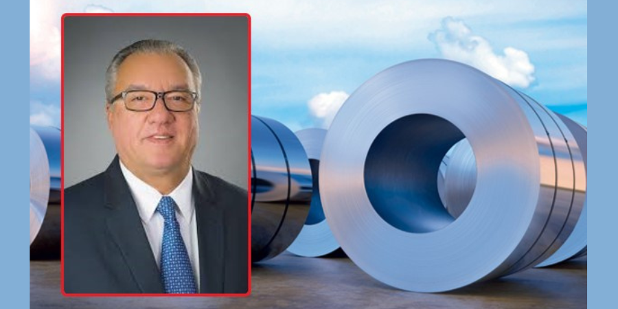
Lourenco Goncalves Board of Directors, president, and CEO Cleveland-Cliffs
Cleveland Cliffs Inc. announces that it has entered into a definitive agreement with ArcelorMittal S.A., in which Cleveland-Cliffs will acquire substantially all of the operations of ArcelorMittal USA LLC and its subsidiaries for approximately $1.4 billion.
Upon closure of the transaction, Cleveland-Cliffs will be the largest flat-rolled steel producer in North America with combined shipments of approximately 17 million net tons in 2019. The company will also be the largest iron ore pellet producer in North America with 28 million long tons of annual capacity.
Lourenco Goncalves, Chairman of the Board, president, and CEO ofCleveland-Cliffs, will lead the expanded organization. “Steelmaking is a business where production volume, operational diversification, dilution of fixed costs, and technical expertise matter above all else,” he says, “and this transaction achieves all of these. ArcelorMittal is a world-class organization that we have long admired as our customer and our partner, and we know for a fact that they have taken good care of their U.S. assets.”
“The acquisition of ArcelorMittal USA amplifies our position in the discerning automotive steel marketplace, and further improves our position in important U.S. markets such as construction, appliances, infrastructure, machinery, and equipment,” he says. “It also adds to our strong legacy raw material profile and growing finishing capabilities. The transaction will enable us to become a more efficient fully-integrated steel system, with the ability to realize all of our operational and financial goals.”
Don't you just wish there was direct, consolidatedinformation that clearly identified the keycharacteristics of new technologies? All too often, there is a dissonance between scholarly discoveries and jargon and the work on the ground (or the shop floor, as it were). But today's resource is different.
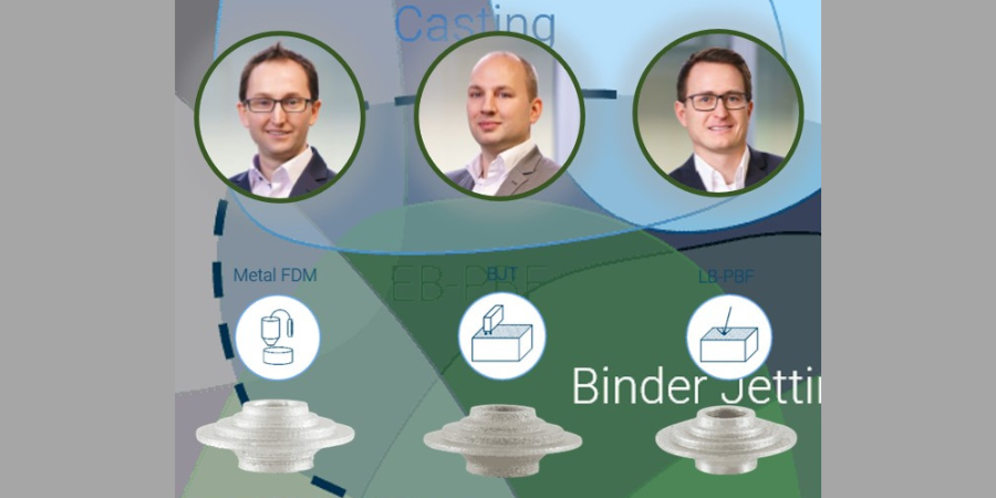
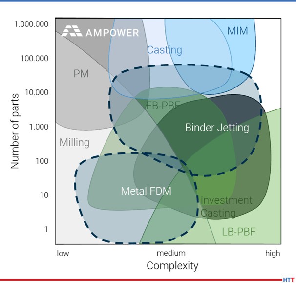
In this Heat Treat Today Best of the Web feature, Ampower presents analytical evaluations of sinter-based additive manufacturing (AM) technologies compared against laser beam powder bed fusion (LB-PBF) and metal injection molding (MIM). The analysis covers over 50 specimens from 9 different system suppliers. The authors are Dr.-Ing. Maximilian Munsch, Matthias Schmidt-Lehr, and Dr.-Ing. Eric Wycisk (pictured above left to right).
An excerpt: "For automotive and machine industry, binder jetting technology and metal fused deposition modeling offer great future potential. They will cover the gap between casting and LB-PBF regarding cost and productivity."
An internationally recognized processor of safety critical automotive fasteners has purchased an industry standard 6000 lb/hr mesh belt furnace to be used in the design and commission of products.
The system includes a computerized loading system, controlled atmosphere mesh belt hardening furnace, oil quench system, post quench system, mesh belt tempering furnace, soluble oil system, and CAN-ENG’s PET™ SCADA System.
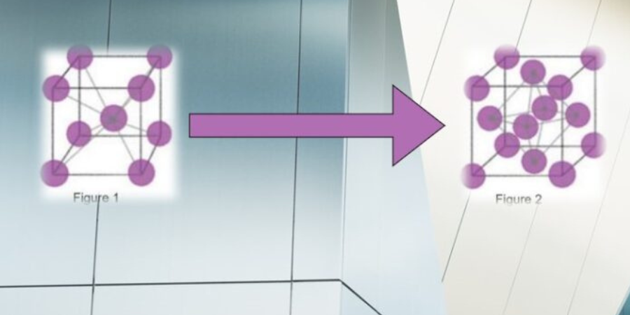
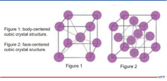
Graphic of Atomic Structures (Photo Source: AHT Blog post “What’s Happening to Metals During Heat Treatment”)
For this Heat TreatToday Technical Tuesday, check out this Best of the Web primer if you are looking to share a few basic pieces of heat treat info with your trainees. These heat treat fundamentals are about what happens to metals in the heat treatment process, tracing steel heat treating back to the ancient Romans in 223 B.C. — though, Encyclopedia Britannica currently places the origins in Egypt by 900 BC. Heat treatment benefits, atomic structural transformation, and hardenability are all covered here.
An excerpt: “Not every steel reacts the same. Chemical composition can vary greatly between the different grades of steel. Certain alloying elements can greatly increase the hardenability of steels such as nickel (Ni), chromium (Cr) and molybdenum (Mo). Hardenability is not how hard a material is. Hardenability directly relates to the ability of a metal to form martensite and martensistic [sic.] structure upon quenching, which points to…”
An aerospace and medical part manufacturer in Southeast USA recently purchased 5 vacuum furnaces. They will be used primarily to sinter and stress relieve stainless steel components.
Dan Insogna Southeast Regional Sales Manager Solar Manufacturing (photo source: solarmfg.com)
The furnaces were provided by Solar Manufacturing and are part of their Mentor® vacuum furnace series. The model HFL-2018-2IQ furnaces feature a graphite-insulated hot zone, a load weight capacity of up to 250 lbs, and maximum operating temperature of 2400° F.
“Our customer worked directly with our R&D team at our sister company, Solar Atmospheres,” states Dan Insogna, Southeast Regional Sales Manager for SolarManufacturing. “The customer received a line of brand new Mentor® furnaces with their custom recipe preloaded and ready to go.”
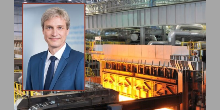
Dr. Arnd Köfler Chief Technology Officer (CTO) thyssenkrupp Steel Europe AG
thyssenkrupp Steel Europe AG, a global manufacturer in high-grade flat steel, has ordered a walking beam furnace. The furnace is designed for heating slabs and will be located at their plant in Duisburg, Germany. This furnace replaces an old reheating furnace. The scope of the contract includes engineering and the largely turnkey delivery of all equipment as well as the erection and commissioning including training.
The new furnace is designed to produce premium sheets, which will service the automotive industry. With a capacity of 380 t/h, it will be integrated in the existing hot rolling mill infrastructure. Additionally, it will be used for heating slabs made of alloyed or unalloyed steel and charged in one and/or two rows. Finally, the furnace features a combustion air pre-heating system to significantly reduce the energy consumption of the overall production. In the long term, it will assist the thyssenkrupp group with achieving their climate related emissions targets.
“The new plant [read: furnace] is scheduled to start operating in mid-2022,” commented Dr. Arnd Köfler, Chief Technology Officer at thyssenkrupp Steel.
Further, “The new plant [read: furnace] will ensure the high surface quality requirements of the automotive industry,” said Antonio Catalano, Executive Vice President of the Tenova Downstream BU, “and support our customer’s forward strategy.”
Tenova, with the companies Tenova LOI Thermprocess and Tenova Italimpianti involved in the project, will design and supply the entire walking beam furnace plant including the charging roller table and the charging machine as well as the related electrical, measuring and control systems. In addition, a sophisticated automation system developed by Tenova LOI Thermprocess will enhance the control and energy efficiency of the furnace.
The production start of the walking beam furnace is scheduled for July 2022.
Heat Treat Radio host, Doug Glenn, discusses how one company saved over $700.00 in hard grinding costs PER GEAR on an 18-inch bevel gear. Joe Powell of Integrated Heat Treating Solutions tells how they did it. Listen to find out how Joe helped this company upgrade their heat treating and bring it into the 21st century.
Below, you can either listen to the podcast by clicking on the audio play button, or you can read an edited version of the transcript.
The following transcript has been edited for your reading enjoyment.
Doug Glenn (DG): This episode is the second in four conversations with Joe Powell on “quench to fit” technologies. Joe is from Akron Steel Treating and Integrated Heat Treating Solutions. We wanted to review a bit of what we talked about last time in our first podcast. Probably the best way to summarize it to say that we’re trying to get heat treaters to think about heat treating differently: not heat treating in the 20th century or even the 19th century, but in the 21st century. What do you say to that?
Joe Powell (JP): Yes, we’re trying to integrate heat treating solutions into the part making process and take advantage of all of the sensor technologies, all of the manufacturing technologies, all of the other advantages that happened in metallurgy in the last half of the 20th century in terms of atmosphere control, temperature control, vacuum furnaces, and integrate them with the part design.
Professor Jack Wallace (Source: Southern Illinois State University website)
DG: You and I were talking about a statement that was said by one of our mutual friends, and the statement was this: “Every metallurgist knows the faster the quench cooling rate, the higher the probability of cracking a hot part.” What do you say to that?
JP: It was professor Jack Wallace who was the head of the metallurgy department in 1997. When he heard about intensive water quenching, he said it would absolutely not work. He was so sure of it, he basically blurted it out, “It will never work! The parts will blow up in the quench!” If anybody knows Jack, they know that’s exactly how he would say it! The other people in the conference room, just kind of looked at each other: Wayne Samuelson from Shore Metal Treating, myself representing Akron Steel Treating, and John Vanas representing Euclid Heat Treating.
The other two heat treaters in the room heard Jack say this and thought, “Well, you’ve got to be right, majority rules,” but I said to myself, “Well I don’t know who Jack Wallace is, (because I didn’t at the time), but I do know Michael Aernoff and he’s introducing this water quenching technology that was discovered by Dr. Nikolai Kobasko back in the former Soviet Union, and I’m willing to give it a try. All he wanted me to do is heat up some parts (made by Timken Bearing) and quench them in a water bath. They were made out of 52/100. I knew 52/100 blows up when you look at it sideways and when you quench it because it’s a deep hardening steel. But if Michael says you can do it, the worst that can happen is it’s going to blow up, in which case everybody will be wearing a face-shield when it goes in the water. The best thing that could happen is that it doesn’t blow up, and we’ll learn something.
About six months later, this prototype tank shows up at Akron Steel Treating with some tapered bearing rings about 10 inches in diameter. We basically said to ourselves, “Let’s heat them up and see what happens.” They came out of the water about 20 seconds after going in; they flash dried as the core heat had just tempered the martensite that we had just formed on the shell; and they didn’t crack. Then, we did a whole bunch more of them. Jack Wallace was present for that demonstration and he just looked at it and said, “We gotta figure out how this works.” That was in 1998, I believe.
Dr. Nikolai Kobasko (Source: wseas.org)
DG: For the reader’s benefit, let’s give them the birds-eye view of what happened.
Last time, you had said that if you can quench a part fast enough in all areas so that you get below the martensite start temperature, then that actually forms what you could imagine in your mind to be a dye shell. It just holds the part in place.
JP: Yes, it’s a hardened shell over the still hot and plastic core of the part. So, whatever the geometry is, that is what you have locked it in.
DG: And that is, in fact, the key, right? Just reviewing what we talked about last time: The key is you lock the geometry of the part in, regardless of what the shapes are, regardless of whether you have hidden holes, whether you have grooves and everything; you lock it in and then all you have to do is keep that shell at below the martensitic start temperature until the core “cools,” which can be calculated. Then, you’re done.
JP: That’s part of the science behind it, yes. At the end of the day, the trick is to have the equipment to be able to do that. The equipment in 1998 was available to do batch quenching. In fact, in 1999, Akron Steel Treating spent a good deal of money to build a 6,000 gallon quench tank that essentially we are still using today at Akron Steel Treating to do intensive water quenching.
DG: Just to be clear, also from our last episode, it isn’t always that it has to be an intensive quench. It doesn’t have to be instantaneous.
JP: Right, so it also works at the other end of the continuum. If you can build a uniformly hardened shell on a part that is made of high alloy air hardening steels, you can actually develop in a gas quench a very uniform, very predictable size change in that shell. That allows you to predict how the part is going to move so that you can machine it before heat treatment so that it literally morphs into the hardened shape that you want.
For instance, take a very thin, complex bearing ring that has a very thin wall that’s made out of a Pyrowear 53 material, which would basically harden up in air — this is part of the DANTE Solutions patent that we discussed last time. [See original DANTE Solutions HTR] The gas quenching process first creates a shell at the thin section, then stalls out the temperature to keep the temperature hot in the gases, which are flowing across the part during the quench, thus allowing the thick sections to catch up. When the thick sections catch up, and once the thin and thick sections have thermally shrunk a certain amount, then you go to the next plateau in temperature cooling. Here, the gases are introduced to the part surface to bring the thin section down first, and then the thick section. You would continue to do that until you get to the martensite start temperature.
[blocktext align=”left”]“If you go too fast, it will crack the part and it will blow the shell off, and that’s what gives water quenching such a bad name; because the core swells up and blows the corner off the part.” – Joe Powell[/blocktext]At the martensite start temperature, you then do the same thing: let the part stabilize at that temperature in the thin and thick sections, and now you have a shell that’s locked in the part. As the part is cooling down into the core, the thin and thick sections of that core are now going to start the transformation to martensite at about the same time. That means that you have a very predictable size change from the thermal shrinkage, and then the following phase change expansion as the austenite kicks over to martensite. That phase change expansion is the thing that you really don’t think about, but that’s what has to be controlled in order not to blow the shell off. If you go too fast, it will crack the part and it will blow the shell off, and that’s what gives water quenching such a bad name because the core swells up and blows the corner off the part.
DG: You said that there is a need for equipment that is able to do what you’re talking about. In the last episode, you said that there are a lot of really good furnace companies out there and that they are “furnace companies” but what they really ought to be doing is focusing on becoming “quenching companies.” Can you expound on that just a bit?
JP: They obviously need to focus on the heating part and that needs to be uniform, but they’ve given absolutely no focus to the quenching part and how uniform it is over time, and between part to part in a load, and how it affects the compressive stresses. The quenching process is more important, in my mind, than the heating process. And yet, there are no specifications on quench zone uniformity. We have to run surveys at Akron Steel Treating all the time on our heating zones. But when you open the door on an integral quench furnace and go into a quench tank, how uniform is that quench? We don’t know. We hope it’s uniform.
DG: We need a “TQS,” a temperature quench survey.
JP: Yes, exactly! Well, it’s really a uniformity survey for the quench cooling rate.
DG: A “QUS,” a quench uniformity survey, how about that?
JP: Doug, we don’t need another acronym– People will go crazy!
DG: I’d like to ask you a few questions about this one example of an 18-inch bevel gear that Integrated Heat Treat Solutions worked on with a company that may remain nameless, unless you would like to name them.
JP: They will remain nameless, but I can tell you that it’s an Ohio company that makes rolls for steel mills. For years, they refurbished and made rolls and “shavs” for steel mills and bought all their gears from outside. They got gears from various sources, and some of the gears that they got over the years were these large roll drives for steel mills in which some of the teeth would fall off. It was very unpredictable. They had the right hardness on the surface, they appeared to be made out of a high quality 8620 carburizing steel, but when cut apart, a very fine gear metallurgist indicated that the teeth, which were a pretty good size, had carburization of 60,000th effective case steps on the tip, but at the root of the teeth, they only had 15,000th effective case steps. This indicated to us that there was an ineffective oil quench after the carburization process. The carbon is there, but it just didn’t quench out to give you the 50 Rockwell effective case steps at the root of the teeth. When we thought about it, we asked, “How do you run bevel gears?” You stack them on top of each other in the furnace, you heat them up, you carburize them, and you quench them. Well, when they’re stacked on top of each other, the oil cannot circulate and quench the teeth either effectively or uniformly, especially at the root where the heat from the hub is constantly coming out. Additionally, you have a long period of basically gas quenching as the oil boils in all of those big teeth at the root.
Image of Quality Inspection from Akron Steel Treating website
So the first thing we said was, “Well, if we do them, we’re not going to stack them up like that.” The second thing we said was, “Why don’t you let us try our water quenching process in our 6,000 gallon tank?” They said they had nothing to lose, and they gave us some gears. Believe it or not, with no gear cutting equipment, they were making the gears on a 5-axis CNC machine. Then they cut the gears out. These gears are not high quantity gears; these are for steel mills and you use hundreds per year, not thousands or millions. And each gear is a pretty good buck, so they can afford to make it on a 5-axis CNC machine. What they did was they cut the gear out by measuring a gear that had a broken tooth, using the metrology that this company also had, (and they have some really cool laser based metrology for measuring parts), and they created a cloud map.
That cloud map was then used to program their CNC machine. They then sent us these rough-cut gears, and we heat treated them. We carburized them for like 20 hours and I think we left around 60,000th of grind stock on them. When they got the gears back, they said, “These are pretty doggone uniform. Do you think we could tighten up and not leave so much grind stock so we could save some money on our grinding?” And I said, “Yes! Let’s try it.” So, on the next part, we left less grind stock. By the sixth sample gear, we had it down to the point where the gear literally was cut in the 5-axis CNC machine in such a way that the gear teeth came out, but they didn’t need any grinding. They were as straight across the top and they quenched to fit.
I asked, “How much does that save you per gear?” They estimated about $750/gear in grinding costs that they were avoiding. “Well that sounds pretty good,” I said, and they said, “Yes, we think so too.” So, we’ve been doing them ever since. We do them in lots of 12 at a time on racks in our radiant tube batch furnace, (it’s an atmosphere furnace), across the aisle from our 6,000-gallon batch quench tank.
[Image.furnace grate] The other thing that we learned from this experience was that the distortion was very, very predictable as long as we didn’t set the hub on the furnace grate. The furnace grate has two areas where the rollers in the integral quench furnace ride on the furnace grate, and those 4-inch-wide tracks essentially block the quenching water from hitting the bottom of the hub. In those areas, their cloud map showed that there was a distinctly different kind of an ovality to the hub on the ones that were quenched on the grate. Now that could be ground out; it wasn’t that big of an ovality. But, it was a non-uniformity that could be avoided simply by raising up the part on the grid allowing the water to reconnect when it rose from the bottom in the batch quench tank to flow around the hub of the part.
The second thing that we learned was that the parts have higher residual compressive surface stresses on the teeth. Our new gears were wearing down case carburized and oil quenched gears that were on the motors driving the steel mill rolls, yet those case carburized gears are the exact same hardness. The difference was that they don’t have as high of compressive residual surface stresses in the case as we developed in our carburizing and intensive water quenching process.
The third thing we learned—and we knew this a long time ago—is that we could cut the carburizing cycle time by about 36%, versus using oil quenching, and still get the same effective case step because we don’t need to drive in as much carbon into the gradient to develop the 50 Rockwell minimum hardness for the effective case step.
[blockquote author=”Joe Powell” style=”1″]“It’s a win-win-win. The customer is happy, we’re happy and it works. This demonstrates that you can indeed quench very, very intensively. We’re talking about 400-600 degrees Centigrade/second of quenching.”[/blockquote]It’s a win-win-win. The customer is happy, we’re happy and it works. This demonstrates that you can indeed quench very, very intensively. We’re talking about 400-600 degrees Centigrade/second of quenching. You can set the shell and once that shell is set, the part predictably changes to a martensitic case-hardened structure on the outside and a relatively ductile core from the 8620 material, and you get a good gear that is very, very consistent that doesn’t need to be ground after heat treat.
DG: The material that they initially came in with was 8620, and you didn’t change the material; you just changed the processing cycle, which was shortened by about 10 hours (36%), and you were able to get the same hardness. But you were also able to get higher compressive residual surface stresses which actually made that bevel gear all the more effective and more robust. And you saved $750/per gear in grinding costs.
JP: Right, and this is from a company that never made a gear before. They had a 5-axis CNC machine and a bunch of smart guys and this new metrology that they have, (which gives them millions of points of measurement on that gear). And at the end of the day, all I can say is it is pretty amazing, because now they can adjust the green size by comparing the post-heat treat cloud map to the pre-heat treat cloud map and constantly whittle away at the amount of grinding stock that they need with each load until they get it to the point where it doesn’t need to be ground.
DG: So all they do is quench it and fit it, thus your statement, “quench to fit.”
JP: Yes, quench to fit. We obviously temper after quenching, but that’s it. They do clean up the hub, and they do clean up the ID of the hub just to make sure everything is square, so that the gear runs true. But the teeth are not ground in this application.
DG: You mentioned earlier that the initial gears that came in had 60,000th effective case step at the top and 15,000 at the root. Did you do tests on yours, and how did it turn out?
JP: They are super consistent. They have the 60,000th required case all the way around.
DG: This is one excellent example of what you’re talking about with “quench to fit.” I know that you’ve had other applications where you’ve done the same thing, so what part do you want to talk about next time?
JP: We’ll talk about fracking pump valve seats that can be made for about $150, which competes against the typical $800 sintered carbide valve seat.
DG: Stay tuned for that. We’ll get that one on our next podcast.


 One of the leading global power, aviation and renewable energy providers has selected a vacuum furnace hot zone replacement. The replacement and modernization of this hot zone is to be updated in a 20+ year old furnace. Once the furnace is updated, it will be installed at the client's facility in Hungary, Europe.