FEATURED NEWS

Effective Integral Quench Furnace Maintenance

OC

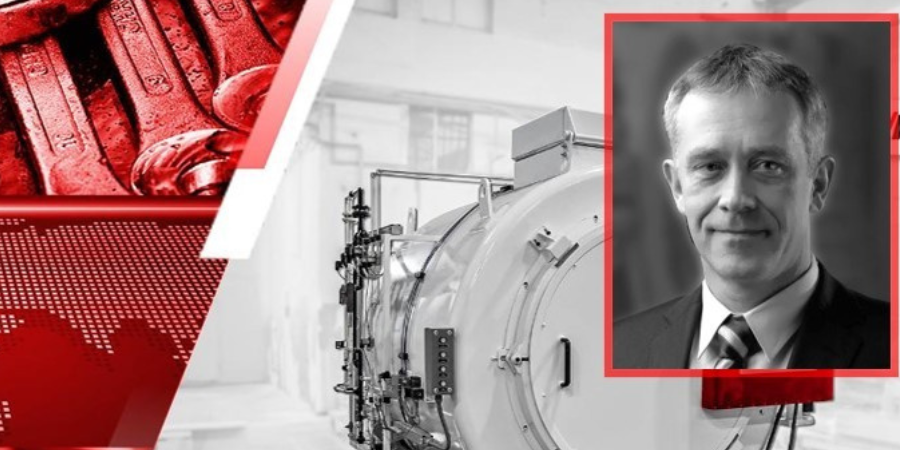
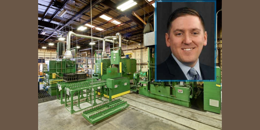
Considerable investment is made when purchasing a batch integral quench (BIQ) furnace. These popular furnaces need specific care and maintenance to keep them in prime operating condition. In this informative article by Ben Gasbarre, president of Industrial Furnace Systems at Gasbarre Thermal Processing Systems, learn how you can protect your BIQ from avoidable downtime. 

This original content article appears in Heat Treat Today’s Air and Atmosphere’s February 2021 magazine. When the print edition is distributed, the full magazine will be accessible here.


Ben Gasbarre
President, Industrial Furnace Systems
Gasbarre Thermal Processing Systems

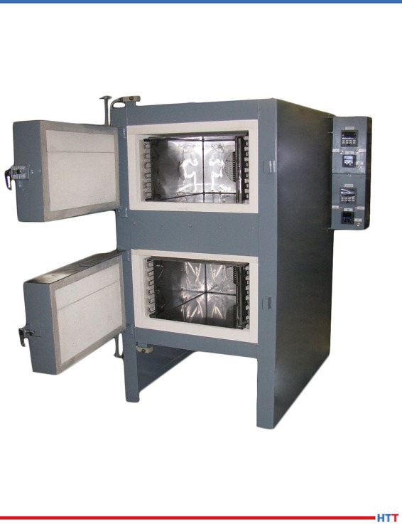
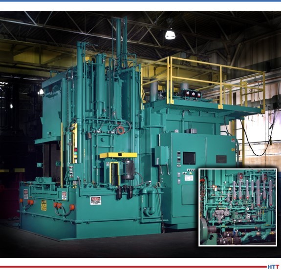
The batch integral quench furnace, or sealed quench furnace, is one of the most popular pieces of equipment in the heat treating industry. The core benefit is its versatility as it can easily adjust to changes in load weight, configurations, and heat treating processes. This makes
it a highly efficient and profitable piece of equipment for both captive and commercial heat treaters.

With all the good that is done in these furnaces, the downside comes in the maintenance of the equipment. By nature, these furnaces are hot, dirty, and have many moving parts, including multiple doors, load handlers, elevators, fans, quench agitators, and pumping systems; this furnace has it all! Although there are many areas of an integral quench furnace, understanding the subassemblies and having a good maintenance program can ensure the equipment operates safely and maintains its highest level of performance year after year.

Maintenance Safety

The discussion on maintenance of any piece of equipment begins and ends with safety. Prior to any work being done on the equipment, safety measures need to be considered based on the work being performed. Certain maintenance activities must be completed while the equipment is in operation; in these cases, proper personal protective equipment must be considered for work being done around hot surfaces, high voltages, elevated work, and potentially hazardous gases. If work is necessary while the equipment is offline, additional safety procedures must be followed, including lockout/tagout of all major power sources, special atmospheres, and natural gas supplies to the furnace.

Integral quench furnaces are considered confined spaces. Prior to entry into the quench vestibule, furnace chamber, and even quench pit, confined space procedures must be followed; hard stops must be in place for doors and elevators. Technicians need to ensure proper oxygen levels and air circulation prior to entry. The buddy system is always recommended when someone is entering the furnace. Prior to returning the furnace to operation, it is important to ensure all necessary safety and maintenance equipment has been removed, all supply lines are receiving designed gas pressures, and proper startup procedures are followed.

For furnace safety during shut down periods, it is wise to review furnace interlock systems and safeties to ensure proper operation. This includes items such as high-limit controllers, solenoid valves, burn off pilots, and other components critical to emergency situations. Additionally, per NFPA 86 requirements, valves and piping should be leak-checked periodically.

Reporting and Metrics for Optimum Performance

Image Source: Gasbarre Thermal Processing Systems

While Industry 4.0 is a popular concept in today’s manufacturing environment, the basic concepts behind the technology are what is important to any good maintenance plan. First, having an asset management system that enables engineers, operations, and maintenance personnel to access maintenance records is critical to ensure they can troubleshoot issues and perform maintenance activities more efficiently. Asset management tools are readily available and can range from well-established cloud-based software systems to simple Excel spreadsheet records. Ensuring important information, such as alloy replacements, burner tuning, or control calibration information, can help operations and maintenance personnel as they plan and assess future equipment needs.

The second concept is preventive or predictive maintenance plans. While these are not interchangeable concepts, the goal of implementing either is to reduce the likelihood of significant unplanned downtime, which can be costly to an organization. Preventive maintenance is a schedule of planned maintenance activities on a piece of equipment using best practices that give the best chance to catch a problem before it arises.

Predictive maintenance uses data and analytics from equipment operations that can be used to predict when problems are likely to occur. There are considerations for either approach, and the evaluation criteria for preventive versus predictive maintenance plans could be an article in and of itself.

Integral Quench Furnace Maintenance

As stated previously, breaking the furnace down into a series of subassemblies is the easiest way to develop an overall maintenance plan for equipment that has many sections and components. Discussed items will include mechanical assemblies, the heating system, the filtration system, atmosphere controls, temperature controls, and furnace seals. Each has its own importance to ensuring reliable equipment performance.

Mechanical Assemblies

Typical load transfer system alignment.

The mechanical system includes the load transfer system, recirculation fans, quench agitators, door assemblies, and elevator system. There are many exterior items that can cause abnormal equipment operation, including position sensors, rotary cam switches or encoders, and proximity switches, that if not operating properly can interrupt or cause failure within the furnace. Position settings should be logged for future reference, and sensors should be inspected regularly. Belts that may be used on recirculation fans and quench agitators should be inspected regularly for damage and excessive wear. Vibration of these items should be monitored as excess vibration can be an indication of damage or wear to the fan or agitator bearings, shaft, or blades.

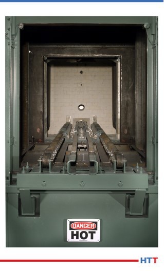
The largest item of concern in this system is the alignment of the load transfer system. Unsuccessful load transfer due to misalignment or obstruction can cause significant furnace damage and create unsafe conditions within the furnace. Internal alloy components should be evaluated for integrity and alignment every six to twelve months. Elevator alignment should be reviewed to ensure smooth operation during the same period. Frequent visual inspection through sight glasses, quench time monitoring, and motor load data can give valuable information of future potential transfer issues within the furnace.

Heating Systems

Whether your furnace is gas or electrically heated, well-maintained systems can have significant impact on the operating efficiency of a furnace. For gas-heated systems, proper burner tuning and combustion blower filter cleaning can ensure optimum gas usage and can also improve radiant tube life. Burners, pilots, and flame curtains should be cleaned at least once or twice a year to ensure proper performance.

Electrically heated systems typically require less general maintenance and have fewer components that are susceptible to failure. Regular checks of heating element connections and electrical current resistance can help to identify upcoming element failure.

The largest and most critical components of reliable process performance are the radiant tubes. A crack or leak in a radiant tube can cause part quality issues. Changes in your furnace atmosphere gas consumption or troubles from controlling carbon potential can be signs of tube leaks. If the radiant tube failure is unexpected, it can also cause significant downtime if replacement tubes are not available. Cycle logs and run hour timers are the best metrics for preventive or predictive maintenance on radiant tubes.

Filtration Systems

Filtration systems are recommended for most integral quench applications. They help to eliminate build up and contamination in the oil recirculation system that flows through the heat exchanger and top/atmosphere cooler on the furnace quench vestibule. Filtration systems typically are comprised of a pump, dual filters, and an alarm system to alert users when it is time to change filters. Maintenance on your quench oil can vary by composition. Quarterly analysis of the quench oil performance is common. However, it is recommended to consult with your quench oil supplier to ensure safe and effective performance.

Atmosphere Controls

Integral quench furnace atmosphere systems can vary both by manufacturer and in overall gas composition. The most common being endothermic gas, nitrogen/methanol, along with options for ammonia or other process gases. Although these items may vary, maintenance remains consistent. Users need to ensure the integrity of the piping system including regulators, solenoid valves, and safety switches.

Endothermic gas lines should be cleaned out at least once or twice a year. Many furnace atmosphere problems can be traced back to endothermic gas generator issues, so it is important to have a well-maintained atmosphere generator to ensure peak performance in your integral quench furnace.

Typical integral quench furnace atmosphere system.

Recent technology allows for automatic burn-off of carbon probes and automated atmosphere sampling. However, probes should be burned off once per week if they are manual. Probes will require calibration and periodic replacement, and they can be rebuilt to like-new specifications. Controllers or gas analyzers that support carbon potential control should be calibrated quarterly, biannually, or annually depending on heat treat specification requirements.

Updates in the automotive CQI-9 specification will require calibration of all atmosphere flowmeters on a periodic basis. Users will need to be aware of this requirement and understand how their gas flowmeters should be calibrated. In some cases, control upgrades may be required.

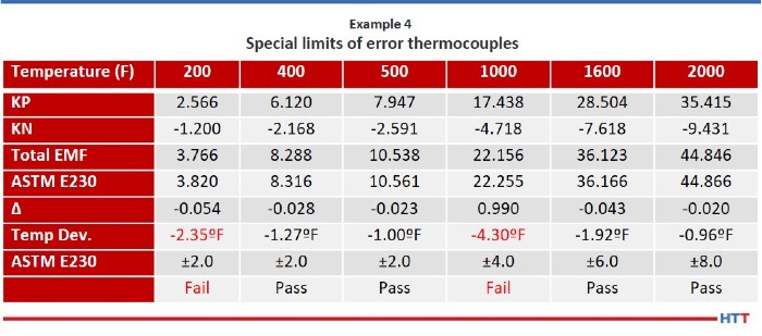
Temperature Controls

Temperature control maintenance typically follows AMS2750 or CQI-9 specifications. This would relate to thermocouple replacement, system accuracy test procedures, and controller calibrations. Depending on the age of the equipment and specification requirement, these items may need to be done as frequently as once per quarter or annually.

Temperature uniformity surveys (TUS) follow similar specifications for frequency. However, a TUS can diagnose areas of the furnace that may need maintenance attention. Having a baseline TUS to reference will help identify changes in furnace performance. Changes to a TUS can indicate burner or element tuning requirements, an inner door leak, refractory damage, fan wear, or radiant tube failure.

Furnace Seals

Integral quench furnace seals can be a source of heartache for any maintenance technicians working to troubleshoot a furnace. Typical seal areas include the inner door cylinder rod, elevator cylinder rods, inner door seal against furnace refractory, outer door seal against quench vestibule, fan shaft(s), and an elevator seal if there is a top atmosphere cooler.

Typical sealing of cylinder shafts are glands comprised of refractory rope and grease. Greasing of these areas should be completed weekly. Outer door and elevator seals are typically fiber rope and may have adjustment built in as they wear, but ultimately will need to be replaced. Frequent inspection of these areas will help identify early issues. Using a flame wand or gas sniffer can help find leaks in unwanted locations. Small furnace leaks can cause part quality issues, and larger leaks can also create safety concerns within the furnace.

Additional Maintenance Items

Other key maintenance items include a bi-monthly or monthly burn out of the furnace heating chamber. This requires the furnace to have air safely injected into the chamber at or slightly above process temperature to allow the carbon to burn out of the furnace. Doing this process on a regular basis will help improve refractory and alloy component life as well as helping to maintain good process control.

Example thermal camera image

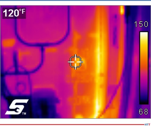
Another helpful snapshot of furnace health is using a thermal camera to take images of the equipment. It is recommended to do this on a monthly or quarterly basis. Thermal camera images can identify hot spots on the furnace outer steel shell that may indicate refractory deterioration or a furnace atmosphere leak. Thermal images can also identify potential issues with motors or bearings on fans and agitator assemblies.

Conclusion

In the end, all furnaces have different nuances that require different maintenance approaches. This could be based on the manufacturer, types of processes being run, or utilization of the equipment. By consulting with your original equipment manufacturer or other furnace service providers, a strong maintenance plan can be developed and implemented. This can include support and training from experienced professionals on that style of furnace. Broader cost benefit analysis should be done as it relates to spare part inventories, resource allocations, frequency of preventive maintenance activities, or investments into predictive maintenance and asset management technologies and how those activities can maximize utilization of each piece of equipment.


About the Author: Ben Gasbarre is president of Gasbarre’s Industrial Furnace Systems division. Ben has been involved in the sales, engineering, and manufacturing of thermal processing equipment for 13 years. Gasbarre provides thermal processing equipment solutions for both atmosphere and vacuum furnace applications, as well as associated auxiliary equipment, and aftermarket parts and service.


All images provided by Gasbarre Thermal Processing Systems.

Effective Integral Quench Furnace Maintenance Read More »

Achieving High Furnace Production

OCYour system is great, but is your furnace performing the best it can? In this Original Content article from Alberto Cantú, vice president of Combustion, Control and Services at Nutec Bickley, learn three key performance evaluation methods and five tips to increase productivity. Check out how implementing these changes applies in the brief case study at the end.


Alberto Cantú
VP Combustion, Control and Services
Nutec Bickley

Adjusting furnace burners not only saves fuel, but can increase the return on investment (ROI) of heat treating operations when confronted with:

  • Problems reaching the desired temperature
  • Longer than expected processing cycles

Every kilogram of product that we fail to create has a corresponding impact on the ROI that we are able to obtain.

Adjusting your equipment may be the solution to reaching your ideal temperature, make your parts heat faster, and increase production. Learn more in this article.

Performance Evaluation Methods

We recommend the following:

1. Establish a benchmark of standard values in your industry to evaluate your performance in each furnace/process and discover the opportunities for improvement.

Example: For a reverberatory aluminum furnace, consumption should be between 2,000-2,500 British Thermal Unit (BTU)/pound. On the other hand a stack melter is in the order of 1,000 BTU/pound. (See “A Melt Performance Comparison” for example.)

2. Measure the oxygen level inside the industrial furnace to determine the current air/gas ratio and whether there is any infiltration.

If oxygen levels are high, the furnace will consume more fuel, flames will be cooled, and you run the risk of oxidizing your product (in the case of metals). If you introduce the correct volume of air, there should be no oxygen in the furnace, since it is all consumed in the combustion process.

This measurement can be conducted extremely rapidly without being expensive or invasive and will allow you to evaluate the status of your processes. If you measure it in-situ, which is more expensive, you will get a consistent reading. Alternatively, you can measure it manually with an oxygen probe. Doing it manually should take no more than a couple of minutes.

3. Obtain a thermographic image in order to determine the furnace wall temperature, to confirm the state of the insulation, and to verify that there are no relevant heat leaks that represent a danger to the furnace or its instruments.

It is vital to check your entire system since sometimes the burners are correctly adjusted, but there are leaks in the doors or walls. The picture to the right shows leaks through the furnace door. If pressure is negative, this becomes an infiltration and you will see more oxygen in the furnace and, therefore, more fuel consumption.

Tips for Optimizing Operation of Your Furnaces

Some recommendations to increase furnace productivity are:

  • Modify the heating curve by adjusting the set point and increasing the initial temperature value to reach the required level faster.
  • Perform ramp-type reductions in temperature to increase production by shortening cycles.
  • Space out the individual parts in the load for greater heat transfer. Increasing the transfer area decreases the heating time and allows us to produce more.
  • Nutec Bickley’s IMPS system intersperses the use of burners to optimize heat transfer thanks to the principles of convection and radiation phenomena.
  • The use of regenerative and recuperative burners in radiant tubes makes it possible to improve the system’s energy efficiency by taking advantage of residual heat from the process.

Implementation

To conclude, here is an example of a customer with an aluminum homogenizing furnace where time was decreased 20% by modifying the temperature curve:

About the Author: Alberto Cantú is the vice president of Combustion, Control and Services at Nutec Bickley. Cantú has more than sixteen years of professional experience, including in the food industry, CFD software consultancy, heating and thermal treatment processes, and general manufacturing industry. He has written nine official publications in a variety of journals about residence time distribution and analyzing different designs. Cantú is also a well-recognized member of Heat Treat Today’s 40 Under 40 Class of 2020; read more about him here.

All images provided by the author.

Achieving High Furnace Production Read More »

Fringe Friday: Future of AM in COVID

Source: AMPOWER Report

Sometimes our editors find items that are not exactly “heat treat” but do deal with interesting developments in one of our key markets: aerospace, automotive, medical, energy, or general manufacturing. To celebrate getting to the “fringe” of the weekend, Heat Treat Today presents today’s Heat Treat Fringe Friday Best of the Web article on how COVID-19 affected the additive manufacturing (AM) industry.

The trajectory of AM has been altered due to COVID, but specifically by what has happened to supply lines, traceability, and service providers. Further topics, details, graphs, and analyses are highlighted in this article by AMPOWER Report: “Severe economy impact from disruption of trade routes.”

An excerpt:

[blockquote author=”AMPOWER” style=”1″]This reorientation of supply chains offers significant potential for Additive Manufacturing. The accompanying flexibility and availability can represent a considerable added value that has hardly or not at all been considered so far and may also justify a cost increase due to risk reduction.[/blockquote]

Read more: The impact of the COVID-19 pandemic to the Additive Manufacturing market


All images from Additive-Manufacturing-Report.com.

Fringe Friday: Future of AM in COVID Read More »

Heat Treat Radio #47: Justin Rydzewski and James Hawthorne on CQI-9 Rev.4 (Part 3 of 4) – Process Tables & New Resources

Heat Treat Radio host, Doug Glenn, conducts Part 3 of this 4-part series with James Hawthorne of Acument Global Technologies and Justin Rydzewski of Controls Service, Inc. about Revision 4 of CQI-9. We will hear about changes in process tables and key information on how to read this revision of CQI-9.

To find the previous episodes in this series, go to www.heattreattoday.com/radio.

Below, you can listen to the podcast by clicking on the audio play button or read the edited transcript.


The following transcript has been edited for your reading enjoyment.

Doug Glenn:  Welcome everybody.  In the first episode of CQI-9 Revision 4, we covered pyrometry and Justin mainly covered it because he’s the expert in this area.  In the second episode, we spoke primarily with James and he shared about changes in the heat treat system assessments (HTSAs) and job audits areas.  Justin, if you don’t mind, would you please review with us just exactly what CQI-9 is?

Justin Rydzewski:  It has essentially three primary sections.  You have your heat treat system assessment, which is often abbreviated as the HTSA; you have the pyrometry section; and then you have the process tables.  The job audit is also something that needs to be completed on an annual basis, so it’s a minor section to the document.

DG:  Today we’re going to talk about process tables and some other support portions of the spec.  Let’s jump in.  James, if you don’t mind, maybe you can talk to us a bit about what are these process tables and why are they important?

James Hawthorne:  The HTSA covers the heat treat system and assessing that system.  There are very unique processes that are covered by CQI-9.  Those are captured in the process table section of the CQI-9 document.

Process Table A covers carburizing, carburnitriding, carburrestoration, austempering, and precipitation hardening or aging.  You’ve got sections like B- this covers nitriding and ferritic nitrocarburizing.  Then you have process table C which covers aluminum.  Process Table D covers induction.  Process Table E covers things like annealing, normalizing the stress relief.  And we go all the way up to process Table I.  So, there is a process table for each unique type of heat treat that is out there in the industry and this allows some very specific topics to be covered in those types of processes.  They all cover pretty much the same thing, so I’ll go back just to run through the headers of Process Table A.

The first portion of it is Process and Test Equipment Requirements.  What are the rules of engagement for those items?  The same thing for pyrometry.  There are specific call outs in the process tables.  If this is part of your system, you have to play by these rules.  Some of them will point you to specific sections of pyrometry.  So, if you’re looking at the thermocouple and calibration of thermocouples, the process table is going to tell you that you shall conform to section P3.1 which covers all of those.

Interview with Justin Rydzewski, James Hawthorne, and Doug Glenn
Source: Heat Treat Radio

It also covers the process monitoring frequency.  How often do you have to check your temperatures?  What are the rules of engagement?  It calls out specifically each portion that may be included in that type of process.  If you have a batch style furnace that covers that process, it has certain rules for you to manage your batch process.  If it’s a continuous furnace, you have certain rules on how you would manage that continuous.  If your process has an endothermic or exothermic generator or even some type of nitrogen methanol system, there are rules of engagement on how to manage or review that system for those items.

Then you get into things like inspection. Your in-process and final test parameters are also covered here.  The last portion of it, in section 5 of the process table, is when you get into things like your quenchant and solution test parameters, and what are the rules for checking that.

What’s really nice about the document is that as you traverse the document, for instance, we have in the quenchant and solution test parameters, it’s A5.1.  The next column over, it tells you what is the related HTSA question.  It is set up in a way where you can go to the HTSA right from the process table and see if you’re compliant to what’s listed there as the shell statement and the requirements or the frequency for checking those.

DG:  That answers another question we were going to address, and that is, how do those process tables work with the HTSA?  It sounds like, in a sense, they are cross-indexed. Is that it?

JH:  That’s correct, Doug.  Like we spoke about in the last interview when we were talking about the job audit, the job audit is set up the same way: It has that same column, it tells you what the related question is, and it affords you the ability to easily traverse the document from the questions in the HTSA to the requirements in the process tables.

DG:  Justin, anything else from you on that?

JR:  The way that I typically frame it for people new to CQI-9 is that the process tables essentially define two things. First, your tolerances for process and test parameters, and second, your frequencies for those process test parameters in testing parts, which are specific to each heat treat process.

As James mentioned, there are nine process tables.  The requirements in each of those process tables are going to be specific to that process.  The requirements within the HTSA are intended to be broad and generic.  They’re intended to be applicable to any organization performing one of those heat treat processes.  As you go an HTSA, you will be notified when to refer to the process table for some specific aspect of the tolerance or frequency portion on that particular requirement.

DG:  It sounds like a lot of work has been put into the cross referencing, making it simple and making it user friendly, right?  So, whether you’re in the process or whether you’re in the HTSA, you can quickly and easily find the portion in the other section of the spec that applies to what you’re doing.

JH:  That’s correct.  Plus, it does afford you the opportunity to find compliance in a simpler fashion.

JR:  And to also specify tolerances and frequencies that are appropriate for that given process.  If I’m heat treating aluminum, I might have a tighter tolerance than that of hardening steel.  They are very two different processes susceptible to different things, so the values need to be different.

DG:  When you’re looking at the changes that were made from Rev 3 to Rev 4 with these process tables, is there anything that jumps out at you?

JR:  I think one of the most notable changes is an item that wasn’t changed, actually, and that was the formatting and grading system retained from the 3rd edition.  The primary focus of our efforts with the process tables this go-around was to enhance that clarity.  The most notable change across many of the process tables was the added requirement to continuously monitor and record that temperature control signature for generators.  So, for atmosphere generators, that temperature side of things needs to not just be monitored, but also recorded.

DG:  Having taken just what we’ve heard today about the process tables, thinking back to what we covered in the last section on the HTSAs, and going back, Justin, even to your first episode that we did on pyrometry, it seems like there is a lot of stuff here.  The CQI-9 comes in at 115 pages long, I’m guessing there are going to be people that start dipping their big toe into this thing and say, “What the heck?  I’m struggling here!  I don’t understand.  What’s required of me?”  From what we’ve talked about, before we hit the record button, there are some other very helpful things in this spec besides these table requirements and things of that sort.

Let’s talk about those a little bit.  What are some of those other resources that will help simplify the execution of this spec?

JR:  There’s a lot to it, but the underlying intent was not to confuse or bombard the organization with unnecessary rules and just allowing people to figure it out on their own.  Everything goes through a “stink test” as we’re writing this up.  Everything must make sense to us.  If it doesn’t, it’s typically not added in or it’s refined and beat up until it is okay and then added in.

What can we do or what are the things that would be helpful to the end-user to make sure that they’re adhering to these things and that they understand to a point where they can adhere to it? It is not uncommon for me to find my customers having no problem following the rules so long as they know what they are so that can understand them and they make sense.

To convey that and get that buy-in, we’ve added a few elements and refined others.  I think the most significant one, and it is in the section within the document that I reference most, is the Glossary of Terms.  There is a lot of really good information in there.  It’s not that I’m referencing the Glossary of Terms because I don’t understand what the word “calibration” means or what the difference is between a “control thermocouple” and a “monitoring thermocouple”, it’s how did we define those terms relative to CQI-9 in terms of CQI-9?  How did we intend that word to be utilized?  Sometimes you can find those little bits of detail that make it easier to understand or to capture what some of the requirements are for that are noted within the rest of the main document.

JH:  There are also some illustrations added to the Glossary as well.  There were a couple there before, but there was some refinement to those illustrations that were in there.  Even those harder to define portions where we put those illustrations to help drive home the intent of the message, I think that was done very well in the Glossary section.

DG:  Would you say, James, that that’s the major change to the Glossary, or are there other things that changed there?

Source: Markus Spiske st pixabay.com

JH:  We went through the entire document from cover to cover.  There are many, many minor changes across the board, but there were some definitions that were added to the Glossary as questions came up during our normal meeting cycles, or that came from end-users when asking them how we should define something.

As those questions came in, we added those definitions to help with that guidance.  Especially, as Justin said, as we’re talking in the meetings, if we’re hammering away at it and we have it digested in the room – we understand what we mean – how do we send this message to the rest of the users out there in the world?  The Glossary ended up being a great place for items like that, as well.

JR:  Right.  So instead of using six paragraphs to describe a certain requirement or whatnot, just use proper terminology and then let’s define adequately those terms, which may be contested or not fully understood immediately, in the Glossary of terms so that there is a clear idea of what it is we’re trying to get across and not have to make this thing 185 pages.

[blocktext align=”right”]“In the context of this document [the CQI-9 revision 4], the following definitions shall apply.”[/blocktext]A real good example of things added into the Glossary would be terms that perhaps we all take for granted, terms that you understand what it means, but when you poll ten different people, their definitions are just slightly different.  For example, “grace periods” was a word we added into the Glossary.  Not that it’s an overly complicated term to understand, but relative to the document, it can have an impact on how it is you interpret those certain requirements and what it is that it means for you.  “RTD” was another one added in there from a sensor standpoint.  I think another that might get some attention is the inclusion of “sintering” and “sinter-hardening.”  There was a fair amount of contention on the sintering side of things that CQI-9 wouldn’t apply.  Then we included sinter-hardening, but we didn’t necessarily define the difference between the two processes.  Now, there’s a distinction made, and it’s included in the Glossary.

DG:  As far as the Glossary goes then, is there any guidance on when it should be used?

JR:  Personally, I would say as often as possible.  It is an incredibly overlooked portion of this document.  It is amazing how much confusion can result just from misunderstanding a word that was used.  Using the example of “grace period”; it’s not that I don’t understand what grace period means, it’s that I want to know what grace period means specific to CQI-9.  How is it intended to be utilized?  My definition might be different.  I want to make sure that I’m lining myself with the definition of the word as it’s defined.

There is a statement at the beginning of the Glossary that says, “In the context of this document, the following definitions shall apply.”  So, it’s within the context of this document.  I may have a different context of that word, but it doesn’t matter what my definition is, it only matters as to how it’s defined within this book, the context of this document.

DG:  That’s a good encouragement to have people refer to that Glossary.  Even if you think you know what the word means, it’s probably not a bad idea to make sure that you understand how it’s being used in this document and don’t impose your own definition.

JH:  There is one other thing I would offer, as well.  I totally agree with what Justin is saying, and I think this speaks volumes or reinforces the things that we’ve talked about already on how one portion of the document supports the other portion of the document and supports the other side.  This document, through and through, supports itself.

[blockquote author=”James Hawthorne, Acument Global Technologies” style=”1″]This document, through and through, supports itself.[/blockquote]

DG:  Let’s jump to instructions.  Probably the most important part of any spec or document is the instructions.  Let’s talk about those for a moment, including maybe references, illustrations, figures, and things of that sort.  Major changes?  What should we know about instructions, references, illustrations and figures?

JR:  There are support elements within the document that we’ve spoken about with the glossary of terms and what not, but there are also instances where instructions are called up… Step-by-step instructions on how to do something so that you can feel confident that you’re doing it correctly.  For doing the HTSA (heat treat system assessment), there are instructions for completing that with the process for going about doing the assessment there, or even as simple as completing the cover sheet for the document or the job audit.  There are instructions provided throughout to try to encourage and support someone’s effort in adhering to the requirements in the document.

DG:  Let’s talk about references, illustrations and figures.

JR:  Within the pyrometry section, specifically, there are a lot of instances of illustrations.  For the system accuracy testing illustrations, the intent is instructional.  It is to allow someone a means of seeing it visually both how it’s to be performed and how to correctly perform it.

Whether it’s a probe method A system accuracy test versus a probe method B system accuracy test, the illustrations included now are a bit more clearly refined.  The focus was on eliminating anything that was unnecessary from that illustration to allow the user to more easily focus on those elements that are critical.  The user will find a lot of improved illustrations throughout the pyrometry section.

You might have no issues performing a system accuracy test and you might have been performing them for some period of time. However, it’s still a pretty good idea to make sure that you’re doing it in the manner that CQI-9 requires in order to see if there is anything in there for added guidance and to make sure that you’re not overlooking something. That just includes simple math to perform one of those tests.  Those are also illustrated to show progression of how to go about doing that test properly.

DG:  Are there other resources within this spec that are available to help the user?

JR:  If there is still confusion, it’s not hopeless.  There are other means by which people can reach out to try to get clarification on different interpretations of requirements.  James and I just recently participated in a roll-out where we had a Q&A for people to bring their questions regarding confusion around certain requirements. We provided answers from a clarity standpoint.  That support doesn’t go away, nor is it just available at special events like the roll-out.  At any time, people can, and often do, email into the AIAG with their questions, looking for guidance on certain matters.

If it’s as simple as- “I don’t understand question 214,” write in and ask the question and see if you can get some additional guidance.  If it’s “I don’t understand pyrometry,” that’s a bit of a broader question and you’re probably not going to like the answer you get back (~chuckle~) and you’re probably not going to get what you’re looking for in the answer you get back, but there are many other sources for support outside of the document.

Justin and James recommend reading the whole document and participating in question submission forms to gain a greater understanding and voice in the CQI-9 requirements.

If the document doesn’t have enough, look outside the document.  The AIAG is one of those sources.  Your customer is another one.  If you work with outside service providers (I’m speaking from my world of things – pyrometry), lean on them for guidance and things you don’t understand.  I have my nose in these documents constantly, so my understanding of it is pretty alright.  I can afford some additional guidance or interpretation.

I guess the advice I would have is don’t jump at something blindly and say “it’s going to be enough.”  You’re going to want to have something behind you to give you a little bit more substance than that and to have some confidence in what you’re doing. Otherwise, it will have the tendency to snowball on you.

DG:  Because these documents are “living documents”, they are continually evolving.  Let’s say someone has a suggestion for a change that they would like to see made in a future Rev 5, what should they do?

JH:  At the back of the book, we have what’s called a maintenance request form.  The maintenance request form is a very short and sweet form that allows document users to submit for committee review what changes they believe should be made.  This would give them the forum to always have their voice heard and how they feel, or believe, something should be managed.

To go back to what we were talking about, the CQI-9 technical committee still meets quarterly.  As Justin alluded to, we had questions from the roll-out, but a good portion of our first post completion meeting was answering questions for the heat treater at large to help give that clarification.  And, when we come across a question where we don’t really know what the person is asking or looking for, we give those questions back to our AIAG representative. They may reach out to that submitter to gain clarity on what was being asked so that we can give the best answer possible, not just potentially dilute it by giving an answer just of the sake of answering the question.

There is a lot of opportunity there and as these maintenance request forms come in, they will be handled.  They’ll be handled with the committee and the group will work on it and develop the best answer.  That answer may be, let’s look at making a change, whether that’s through some form of errata or by “putting it on the shelf” until – hopefully a long time from now – we look at a 5th edition. This gives us the ability to capture these things and make sure that it stays on out radar.  We want to make sure that they’re taken care of with the urgency that’s needed.

JR:  I think an item of note here, to make it clear, is any of those maintenance request forms that are sent in, all of them are reviewed by the technical committee.  They are all reviewed.  Anything submitted will make its way in front of that committee to be reviewed to on their agenda.

DG:  What should these forms be?  Is it just for document changes or for other things as well, for suggestions and whatnot?

JR:  It’s for document changes as well as a suggestion box form.

DG:  We’ve covered a lot in this third episode.  We’re going to have a fourth episode that is going to deal with some practical tips from you guys on the actual execution of these things, but is there anything else that you would want to tell the listeners regarding the spec itself?  Any other concluding comments?

JR:  From a process table standpoint, this was something that was reiterated throughout the entire roll-out presentation: it really does take reading the entire document to capture all of the changes.

Some of them are quite minor and some of them stand out as being significant, but for the most part, they are minor, and sometimes minor ones can be very easy to overlook.  There used to be requirements for calibrating your hardness testers on an annual basis.  Those requirements have now been expanded to all lab and test equipment that require an annual calibration.

Another element that was included in the 4th edition was we made an effort to increase the clarity and guidance for the use of exceptions that are applicable to section 4 requirements of the process tables.  For example, these would be used if you’re employing a surrogate test piece in lieu of sectioning some large or expensive product.  If anyone is interested, the clarity is included on page 9.

But make note, these are not blanket requirements; these exceptions require customer approval and ultimately OEM approval, so they must be documented and approved by a customer and increased in your PPAP (Production Part Approval Process) control plan.  There is a fair amount of added clarity on that topic, so it’s something people might want to take a look at and dive into just to make sure that they’re familiar with it.

DG:  James, any concluding comments from your side?

JH:  I think I’d just reinforce a little bit of what Justin was mentioning earlier.  Read the document.  Read as much of it as you can and try to understand as much as you possibly can.  We made a lot of changes.  Some of them are very minor, but some of those minor things could potentially be overlooked if you don’t step back and take a moment to understand the document and how each system, or each portion of the document, works with each other.

DG:  The next episode is going to have some practical tips.  We’re going to pick the brains of these two gentlemen on navigating Revision 4.  You won’t want to miss it.  There are going to be opportunities here to basically figure out some of the details.

If you have questions, feel free to send them in.  You can email htt@heattreattoday.com if you have any questions and we may get those answered.


Doug Glenn, Publisher, Heat Treat Today

Doug Glenn, Heat Treat Today publisher and Heat Treat Radio host.


To find other Heat Treat Radio episodes, go to www.heattreattoday.com/radio.

Heat Treat Radio #47: Justin Rydzewski and James Hawthorne on CQI-9 Rev.4 (Part 3 of 4) – Process Tables & New Resources Read More »

Tool Manufacturer to Receive Heat Treat Furnace

HTD Size-PR Logo

Maciej Korecki
Vice President Vacuum Furnace Segment
SECO/WARWICK
(source: SECO/WARWICK)

A tool manufacturer has ordered a retort furnace with vacuum purging for oxidation. While oxidation is primarily used in demanding industries such as automotive and aviation, the technology is increasingly widespread among tool manufacturers.

The retort furnace for the oxidation process operates under a nitrogen and hydrogen mix, then under steam. This furnace can be adjusted to the individual needs of the client, providing the appropriate final hardness and color of the workpieces. According to the supplier, the solution will also enable tempering after vacuum purging.

“Innovations originate . . . also from using the knowledge of our partners and listening to what they want to say,” said Maciej Korecki, vice president of the vacuum segment business at SECO/WARWICK. “We are glad that we can deliver another furnace and increase the production capacity of our partner.”

Tool Manufacturer to Receive Heat Treat Furnace Read More »

Thermocouples: Know Your Limits

OCAre you a heat treater who makes thermocouples? How do you stay within limits? What do you need to know when using specific thermocouple materials? Read all about it in this Heat Treat Today Original Content article by Ed Valykeothermocouple specialist at Pelican Wire, Naples, FL.


Ed Valykeo
Thermocouple Specialist
Pelican Wire

We are often asked, what is the difference between special limits of error, standard limits of error, and extension grade thermocouple wire? Today’s discussion will review base metal thermocouple tolerances for special, standard, and extension grade wire. First, we will look at the difference between a thermocouple wire producer and the different types of thermocouple wire users. Then, we will look at emf (electromotive force) data for single leg thermoelements and how to determine temperature deviation. Finally, we will touch on how thermocouple wire is manufactured at the wire producer.

Thermocouples

Since thermocouple materials are supplied with different levels of accuracy depending on the standard being used, ANSI/ASTM E230 identifies accuracy requirements for standard limits of error, special limits of error, and extension grade.

The two tables below list the accuracy requirements for standard, special, and extension grade thermocouples and thermocouple wire.

A thermocouple is a sensor for measuring temperature in which a pair of wires of dissimilar metals are joined at one end. The other end is connected to an instrument that measures the difference in potential created at the junction of the two metals.

From this definition, we know that a thermocouple must have two wires of dissimilar metals. For example, the positive leg (KP) of a Type K thermocouple consists of nickel and chromium, the negative leg (KN) is nickel, aluminum, and silicon. Type J consists of iron in the positive leg (JP) and copper nickel in the negative leg (JN). It has taken decades for thermocouple wire producers to perfect the chemical composition of each thermoelement to achieve desired emf outputs. When these elements are melted, the electromotive force generated can be predicted.

A thermocouple wire producer is where a thermocouple gets its start. Raw chemical elements such as nickel, copper, chromium, manganese, and silicon are melted to form individual thermoelements. The process of melting metals into a usable wire size is done in several ways. A typical method is to melt and pour to form ingots; ingots are then broken down into bar form, and then the bars are hot rolled into rod before the rod is cold drawn to the desired wire size. Producers supply thermocouple materials in rod, wire, and strip form. There are only a few thermocouple wire producers left in the world today.

Measuring Electromotive Force (emf)

As mentioned above the first step in the life of a thermocouple is the melting step. Chemical elements are gathered and weighed to the desired recipe. The goal is to hit the desired emf curve for a single thermoelement. The process is repeated for the other leg of the thermocouple. Each thermoelement leg is calibrated to get emf data. Once emf data for each leg is known the data can be matched to hit the desired calibration i.e., special, standard or extension grade limits of error. Examples 1 & 2 are emf data provided by a thermocouple wire manufacture. This data is typically posted on each thermoelement spool.

If the emf data is known for each thermoelement, it is easy to compute the total emf output and temperature deviation in the case that these two spools are combined to make a thermocouple.  Below, Example 3 shows how the two individual thermoelements are combined and the resulting emf, and temperature deviations are computed.

Measured emf output of single thermoelement

Step 1: Algebraically add the emf outputs for both thermoelements at each temperature point. (KP + KN)

Step 2: Take the total emf output of both the KP and KN and subtract value from the tables listed in ASTME230 Standard Specification and Temperature-Electromotive Force Tables for desired thermocouple types.

Step 3: Take the delta value and divide by 0.022mv.  (For Type K, the nominal millivolts (mv) per degree is 0.022)

The results show that as a thermocouple, the material meets special limits of error.

Factoid:  One quick rule of thumb for Type K Special Limits is ±2.0°F up to 500°F and then ±0.4%.

Buying and Using Bare Wire

It is important to understand thermocouple wire producers sell bare wire in matched sets. By selling in matched sets the producer can guarantee the total emf output falls within special, standard, extension grade limits of error. As mentioned earlier, wire producers melt thermoelements to a precise “metallurgical recipe.” Even though these recipes have been proven out over time, there are still factors which affect the emf output. For example, impurities in raw materials, condition of the furnace and melting practices all contribute to emf results. Since thermocouple wire producers know the emf output of each thermoelement they can mix and match melts to minimize any scrap.

Caution should be taken if bare wire thermocouples are going to be fabricated from positive and negative legs that have not been matched by the wire producer. Any one individual thermoelement can have emf output that, when matched with the opposite leg, could cause the total emf output to fall outside the required tolerances.

If we required special limits of error thermocouples the results of matching the KP and KN leg in Example 4 below, shows the material would not meet special limits at 200 and 1,000 degrees.

The example of KP and KN shown in Example 4 does not meet special limits of error at 200ºF and 1000ºF. What about standard or extension grade tolerances?

Reviewing Table 1, we can see that the tolerance for standard limits of error is ± 2.2ºC or ± 0.75%. By applying note 2 the tolerance for standard limits of error at 200ºF is ±4.0ºF so this combination of KP and KN would meet the tolerances for standard limits at 200ºF. At 1000ºF the tolerance for standard limits is computed as 1000ºF X .75% or ±7.5ºF. This combination does in fact meet the standard limit tolerance at 1000ºF.

What about extension grade? Would the above KP and KN meet extension grade tolerances?  Let us refer to Table 2. Table 2 shows that from 32ºF to 400ºF for special limit extension grade the tolerance is ±2.0ºF. Our matched KP and KN above has a temperature deviation at 200ºF of -2.35ºF.  This match would not meet the requirements of special limit extension grade at 200ºF. However, this combination would meet the special limits requirement at 400ºF. What about standard limits extension grade? This combination would in fact meet the tolerances for standard limit extension grade.

Factoid: The tolerances for special limits, standard limits, and extension grade, thermocouples and thermocouple wire are the same! The only difference is that EX, JX, KX, and NX extension grade have a maximum temperature range of 400ºF. Maximum temperature range of TX is 200ºF.

Types of Thermocouple Users

One type of thermocouple wire user, whom we will call an intermediate user in this article, receives the bare wire from the producer and performs additional processing. This processing typically consists of adding an insulation of fiberglass, high temperature textile, extruded thermoplastic or tape to the individually matched pairs, then commonly adding an outer jacket over both thermoelements. There are any number of custom constructions that can be part of this processing, including but not limited to shielding, metal over-braid, multi-pair cabling and combinations or layers of the above insulations. The bare wire can also be incorporated into a mineral insulated cable. Careful consideration is taken to ensure only the two thermoelements matched originally by the bare wire producer are used in the processing. After the insulation process, the wire is then ready to be sent to another type of thermocouple wire user or consumer.

Very commonly, an intermediate user, like Pelican Wire, sends the processed bulk wire to temperature sensor manufacturers. Although not an end user, these sensor manufacturers would still be considered users of thermocouple wire. However, they are distinguished from intermediate users, because of the assembly or fabrication work they perform with the wire. As stated previously, it is crucial the wire be sent to the sensor manufacturers in matched pairs to ensure the calibration accuracy of the wires.

Simply put, an end user is an entity which uses a thermocouple sensor for measuring and monitoring temperature in a manufacturing, or laboratory environment. Examples of this are heat treating metals, curing composites, food & drug processing, monitoring in the oil & gas sector and power generation. The critical nature of the outcomes of these processes point to the importance of accuracy and reliability in a thermocouple and thermocouple wire. An important element of this is understanding calibration of thermocouple wire and the Limits of Error classifications.

There is more information that cannot be covered in this discussion. If you are an end user with questions regarding this subject it would be advisable to contact an experienced thermocouple wire user who processes and does assembly work regularly with the wires for additional guidance.


About the Author: Ed Valykeo, a 40-year veteran in the wire industry, many with Hoskins, is a thermocouple specialist who has worked with Pelican for 10 years.


All tables provided by Ed Valykeo at Pelican Wire.


Thermocouples: Know Your Limits Read More »

Power Tool and Medical Heat Treaters Receive Furnaces

HTD Size-PR Logo

Ipsen Vacuum Furnace
Source: IpsenUSA.com

A North American heat treat supplier will be sending a vacuum furnace to a power tool manufacturer in the U.S. and a medical implant manufacturer.

The supplier, Ipsen’s Vacuum Technology Excellence Center, was awarded these two furnace orders at the beginning of 2021. The power tool manufacturer will receive an Ipsen TurboTreater® as part of a plan to increase production capacity. It will be the ninth vacuum furnace at that location from the U.S. supplier .

The medical implant manufacturer, looking to expand production capacity, chose Ipsen’s MetalMaster® external quench vacuum furnace. The furnace will be designed with an all-metal hot zone for long, high temperature cycles. Its multi-staged pumping system is capable of providing low residual oxygen levels for processing titanium components.


(photo source: powertools at pixabay.com)
(photo source: Sasin Tipchai at pixabay.com)

Power Tool and Medical Heat Treaters Receive Furnaces Read More »

USAF Receives 18 Heat Treat Furnaces

HTD Size-PR Logo

Lucifer Furnaces, Inc. Dual Oven

18 AMS2750 compliant furnaces and ovens for the U.S. Government were recently completed and shipped. Air Force bases throughout the U.S. will use them to support airplane and helicopter repair and maintenance, processing a wide range of materials from aluminum to tool steels.

The models, supplied by Lucifer Furnaces, Inc., include 5000 Series Heavy Duty Single Chamber Furnaces, 8000 Series Dual Chamber Furnace/Oven combos, 4000 Series Recirculating Convection Ovens, and DU4 Series Dual Ovens. All models comply with AMS2750 Class 2 (+/- 10 F) and Class 5 (+/- 25 F) specifications with an instrumentation package that includes digital paperless recorder/controllers, high limit safety systems and SCR power supplies. TUS (temperature uniformity survey) and SAT (system accuracy test) access ports are built in for ongoing SATs and TUSs. All models are completely wired and temperature uniformity surveyed in-house prior to shipment.


(photo source: Cassio Nunes at unsplash.com)


All other images provided by Lucifer Furnaces, Inc.

USAF Receives 18 Heat Treat Furnaces Read More »

Heat Treating Capabilities Expand for Medical Device and Implant Manufacturer

HTD Size-PR Logo

Solar Manufacturing Mentor® Furnace
Source: Solar Manufacturing

A medical device and implant manufacturer in the Southeast USA recently received a vacuum furnace. The furnace will be used to age harden and anneal medical devices and implants.

The Model HFL-2018-2IQ Mentor® vacuum furnace by Solar Manufacturing features an all-metal insulated hot zone, a load weight capacity of up to 250 lbs., and a maximum operating temperature of 2400° F.

Dan Insogna
Southeast Regional Sales Manager
Solar Manufacturing (photo source: solarmfg.com)

“We were awarded the project based on our relationship with Solar Atmospheres and our quick furnace delivery,” states Dan Insogna, southeast regional sales manager at Solar Manufacturing. “Together, we delivered the Mentor® furnace along with a water system, and a custom heat treat recipe for the medical grade components being processed. Our customer was up and running with their new… furnace within a week of delivery.”


(Photo Source: BruceBlaus – Own work, CC BY-SA 4.0, https://commons.wikimedia.org/w/index.php?curid=44967235)


Heat Treating Capabilities Expand for Medical Device and Implant Manufacturer Read More »

MTI & FNA Announce Heat Treat Today as Exclusive Media Partner

HTD Size-PR LogoThe Metal Treating Institute (MTI) and Furnaces North America announced that they have signed a new media partnership with Heat Treat Today out of New Castle, Pa. Heat Treat Today is one of the heat treating industry’s leading publications, reaching heat treaters through their print, digital and social media platforms.

“2020 brought on many changes to many companies, and MTI,” says Tom MorrisonCEO of MTI, “was no different. After looking at the value proposition from numerous publications on who could provide the largest voice for commercial heat treaters, Heat Treat Today’s offerings matched up with the needs and future plans of MTI and FNA.”

Heat Treat Today founder and publisher, Doug Glenn, added, “We are excited about the media partnership with MTI and FNA. Our passion is the heat treating industry and we are looking forward to providing a strong voice for MTI members to the captive heat treaters throughout our readership.”

MTI will release MTI’s Commercial Heat Treating in Heat Treat Today’s printed magazine. This section will focus on sharing why outsourcing part or all of their heat treating to a MTI commercial heat treater could be beneficial. Content will also include articles on safety, Industry 4.0, digital business strategies, and automation.


Tom Morrison image provided by Metal Treating Institute. All other images provided by Heat Treat Today.

MTI & FNA Announce Heat Treat Today as Exclusive Media Partner Read More »