When it comes to hardness testing nowadays, the process does not have to be done manually; automation has taken much of the burden away from operators. But which way produces the better result?
In this Heat Treat Today Original Content feature, Buehler recently published the results of a time study that compared case hardness testing of automotive crank pins and journals using both automation and manual testing. Find out which method showed a definite edge over the other in terms of time saved, less part manipulation, fewer errors in data transcription, and lower variability between performing tests.
EXECUTIVE SUMMARY
A study shows an operator time savings of 86% for making and measuring indents in three locations of crank pins and journals when using automation compared to manual testing. There was less part manipulation, fewer errors in data transcription and lower variability between operators performing tests.
INTRODUCTION
A large automotive manufacturer wanted to investigate the potential time savings of using automation for hardness testing crank pins and journals. Their existing process required two skilled operators per shift, two shifts per day, seven days per week. Tests were performed in three specified locations, two at forty-five degrees off axis and one perpendicular to the axis. Specified locations are critical, as missed locations could lead to manufactured parts being held in quarantine until further confirmation can be performed. Also of concern are failed parts that were inadvertently passed being installed and ultimately being prone to catastrophic failures. Data transcribing error was also a concern; if part information was entered incorrectly in a separate database it would cause mismatched data to lot number. When this occurs, it causes parts to become quarantined until the part information can be verified. With the total scrap cost being a considerable factor, skilled trained operators are needed for testing. Round robin testing is also used to determine the variability between operators. Qualifying new lines put into production increased testing by a factor of three to five times the normal operation analysis rate.
OBSERVATION
Current Process Observation
An evaluation of time to make and measure Vickers indentations on automotive crank pins and journals was established to determine a baseline of time for the existing process. Testing was done on a standalone manual system and required operator time for alignment, making and measuring of indents. The operators would fixture parts in similar orientation to ensure that measurements of the forty-five degree axis were in close proximity to expedite testing and reduce errors in testing. A high degree of manipulation for part alignment is necessary prior to physical testing to ensure accuracy.
It was observed that the operators’ set up time for location took the largest amount of testing time at 60%, measuring indents taking the second largest amount of time at 30% and making indents the third largest amount at 10%. The total amount of indents per pin and journal varied but averaged eighteen indents per section; six in each location. Total amount of indents for a crankshaft, pins being measured top dead center and bottom dead center and journals being measured along split, was 216 indents on average. The total analysis time for making and measuring indents at the specified locations on a crank was nine hours with 8 hours of operator interaction.
Implemented Process
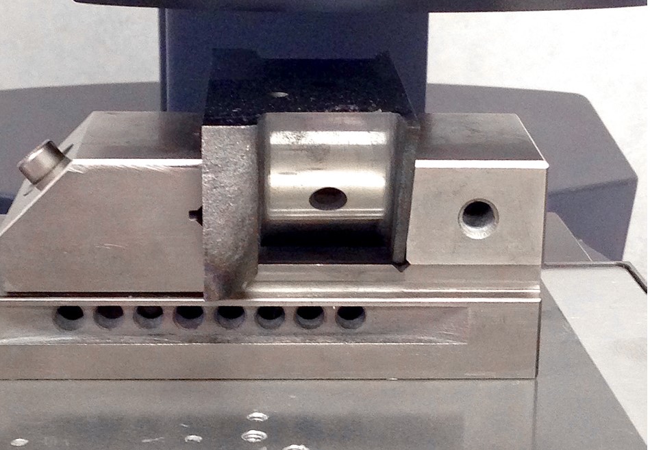
For the implemented process a Wilson VH3100 series Vickers Microhardness Tester with DiaMet software was used. Parts were clamped in a machinist vice and placed on the stage without manipulation of orientation.
Figure 1.1 – Crank pin held in machinist vice (source: Buehler)
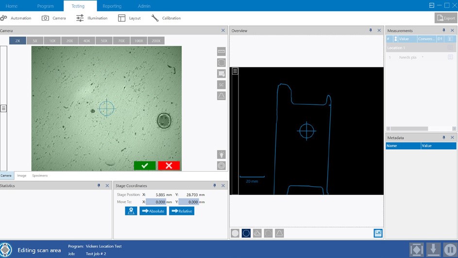
Trace function was used with the overview camera to create a template of the part to be tested; minimizing the set up time for the indent locations. The use of the template reduced the location set up time to 45 seconds in the three areas; two at forty-five degrees and one perpendicular to case.
Figure 1.2 – Trace function template for ease of indent locations (source: Buehler)
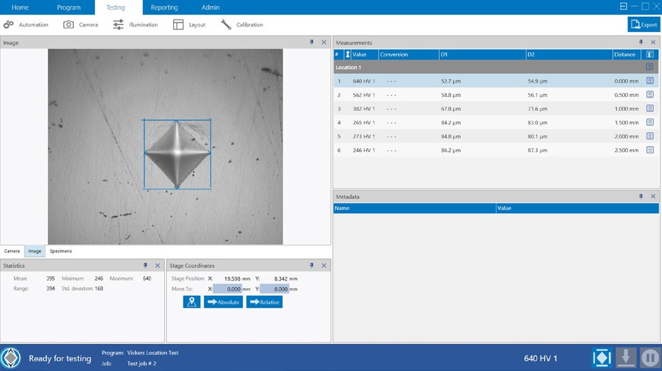
The DiaMet software snapped the template to the part at the specified location and the operators confirmed location. Observation of the set up time, making and measuring indents was 10, 50 and 40 percent respectively. Total amount of indents for a crankshaft was 216 indents on average with of time 1.25 hours with 15 minutes of operator interaction.
Figure 1.3 – Indent make and measure being performed automatically (source: Buehler)
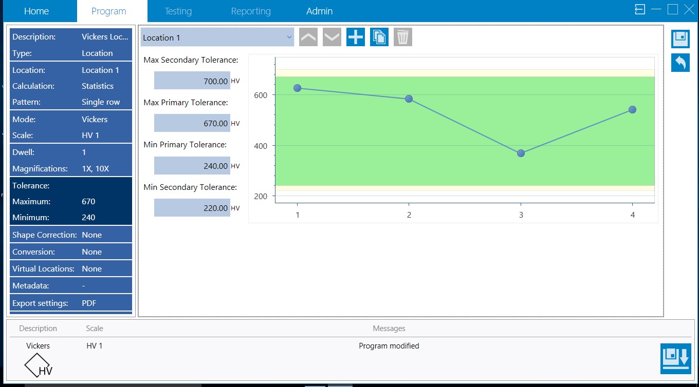
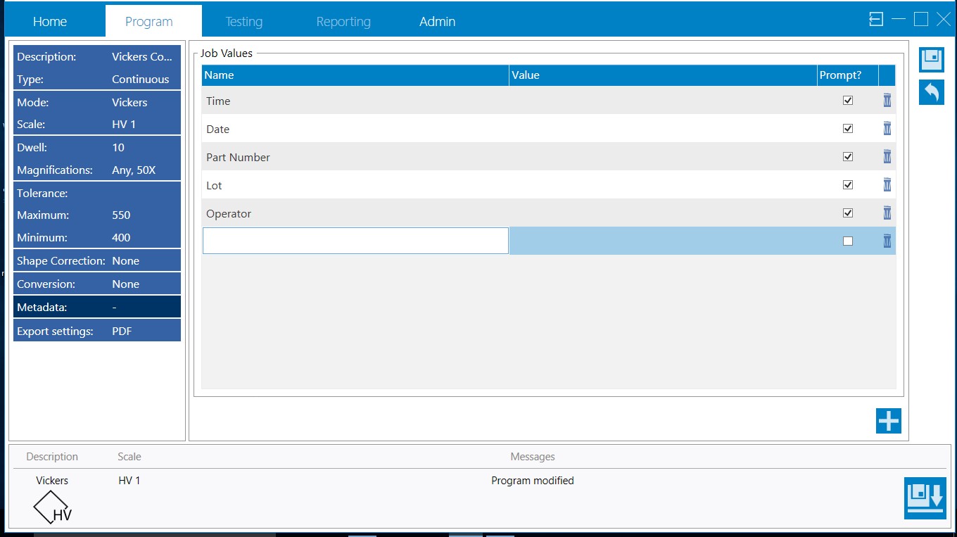
Visual high and low threshold warnings were added to each program giving the operator the ability for quick assessment of parts versus the confirmation after all crank pins and journals were analyzed as it was in previous methodology.
Figure 1.4 – Visual high low threshold warnings to alert operators of hardness thresholds (source: Buehler)
For reporting, metadata was set up to prevent operator errors in transcribing data.
The time study evaluation shows automation saves a significant amount of time with setup as well as the time required to make and measure the Vickers indents. The total amount of time that the operators spend setting the indent profile, measuring and compiling data is reduced by 86% as well as avoiding any errors in transcribing data. Repeatability of testing is increased operator to operator, as variability between operator judgement is eliminated. The combination of using trace function and templates eliminated the need for operators to spend time aligning parts on the stage as well as mitigated the risk of a misplaced indent profile. The increase of visibility of part failure is evident at time of measurement and gives the operator the ability to recheck either an area or total part without the need for extended quarantine of parts for re-examination. Using metadata fields within the Vickers testing program removed transcribing issues which would hold up batches of cranks until records could be reviewed.
Die casting can be tricky to understand; additionally, the term has become something of a catch-all phrase for a production process that covers both low- and high-end technology. In this Original Heat Treat TodayTechnical Tuesday feature, come along with Martin Reeves, Owner of Fontec-Global, LLC, as he takes readers through the die casting process, giving helpful definitions of terms and easy-to-understand descriptions of processes.
The term "die cast" is one many will have heard referring to a particular part; sometimes as a recommendation, sometimes inferring a cheaper alternative, but always as a catch-all for a production process that encompasses a whole range of technologies from cheap and cheerful to the highest technology. So here is a quick overview of what can be termed as "die casting."
(source: fontec-global, LLC)
Die/permanent mold casting has become the dominant casting process for nonferrous alloys of aluminum, magnesium, and zinc, and with the growth of aluminum as a major structural component in automotive design, it is set to maintain that position in the future. This is an overview of the various ways and processes in which permanent metal molds are used today.
Typical metals used in die-casting are lower melting point alloys of aluminum, magnesium, and zinc. Lead and pewter are also cast in this way, and the original process was developed for creating movable type around 150 years ago for the fledgling printing industry. Copper and its alloys of brass and bronze can also be cast in this way, and even some cast irons have been cast in permanent molds with suitable mold coatings as the melting/casting temperatures approach that of the mold steels used.
Many of us will probably have used the process to make lead shot, fishing weights, or toy soldiers (showing my age now) in lead, which can be melted over a candle. Likewise, we see examples of die casting that can be produced in a vast range of sizes, and with high levels of surface finish and accuracy in our everyday life. It is this versatility to produce fine detail, accurate dimensions, and fine finishes that has driven the growth and development of the high pressure machines, which can produce these castings in high volumes (40 – more than 100/hr). This has ensured its continued popularity.
When we talk about die casting, it is normally the automated process using high pressure machines that force metal into a closed die; but there are several different processes that use permanent dies, and even within the high pressure die casting industry there are now different processes in use depending on the product, alloy, and industry. The majority of technological developments in the last 20 years have been in HPDC processes with bigger machines and computer controls.
Types of Die Casting Processes
The three principal (most popular) variations on the die casting process are:
High Pressure Die Casting (HPDC)
Low Pressure Die Casting (LPDC)
Gravity or Permanent Mold Die Casting
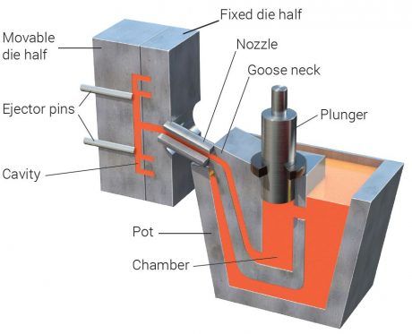
Hot Chamber Machine (source: fontec-global, LLC)
High Pressure Die Casting (HPDC) – This is now the most common form of nonferrous casting production, in which the molten metal is forced into the cavity under very high pressures. This process utilizes two different means of introducing the metal. A hot chamber machine will have the holding furnace installed as an integral part of the die casting machine, and the metal pump is immersed in the metal and forces metal directly into the cavity. Bigger and more sophisticated castings and alloys use a cold chamber process where the metal is held in a separate furnace and transferred into a shot sleeve on the machine linked to the die. It is then forced directly into the cavity by a ram.
Die Casting Machine (source: fontec-global, LLC)
All of these processes have variations that make them uniquely suited to specific types of castings or alloys. The development of novel processes and controls has expanded the scope of HPDC in recent years to the extent that safety critical structural castings can be produced and heat treated.
A historical problem with conventional die castings was the turbulence of the injection process, which caused air and gases to become trapped in the solid metal. Attempts to heat treat these castings resulted in expansion of the gases, which created blistering and eruptions on the surface and a reduction in mechanical properties. New processes, new alloys, and improved controls on die casting machines have now eliminated these issues, and thin-walled structural parts for vehicle bodies and structures are now normal production.
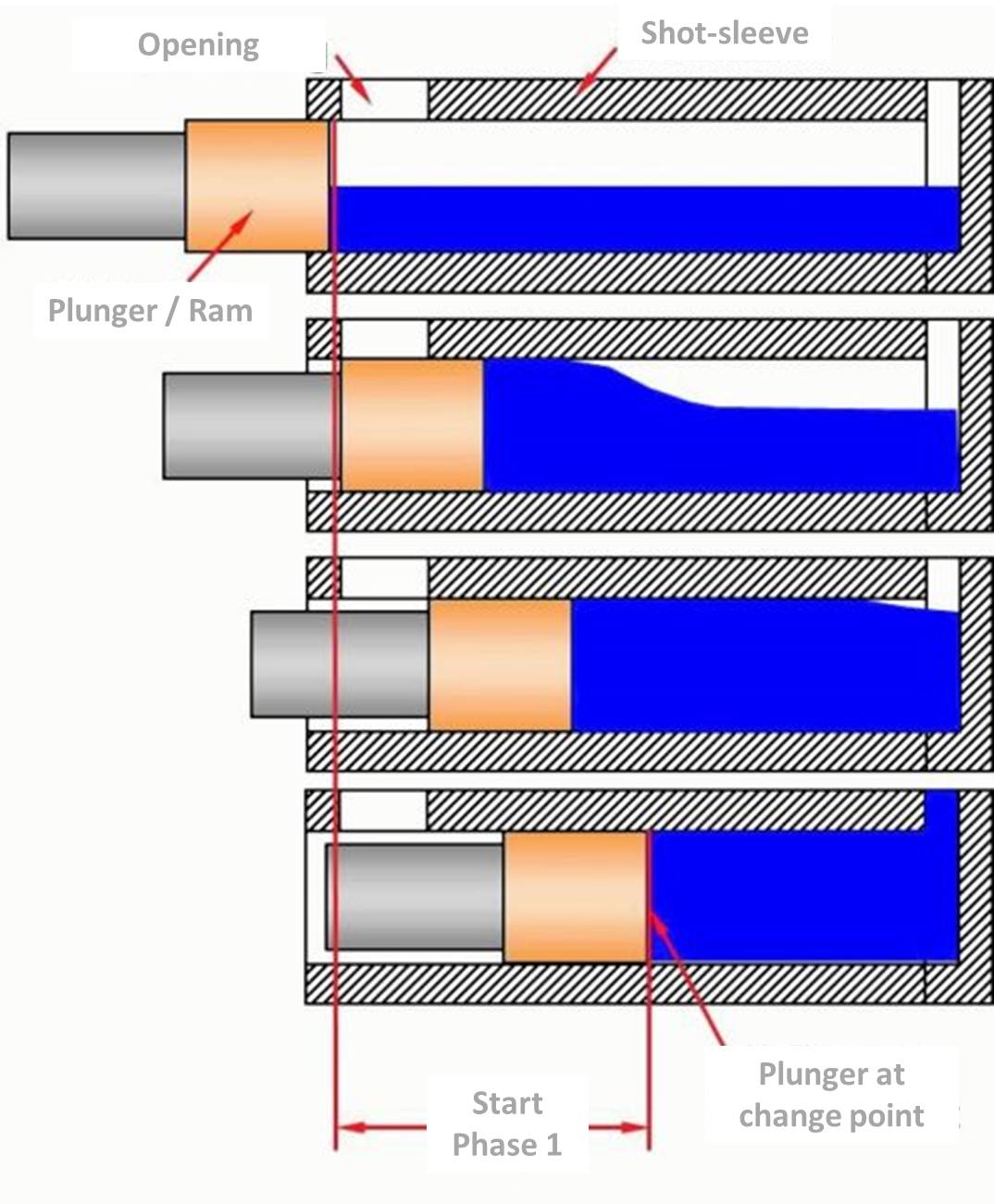
HPDC Ram Shot Control (source: fontec-global, LLC)
The development of bigger die casting machines and the evolution of shot control has expanded the scope and size of parts that can be produced. Shot control now means that instead of the ram simply moving at a steady speed to push the metal into the cavity, the movement profile can be controlled to move the metal gently at first to avoid air entrapment, and then intensifying towards the end of the stroke to ensure complete filling and improvements in metal density. When this feature is combined with vacuum assistance in the die, then the casting quality is improved dramatically, and along with newly developed alloys, can be heat treated to a T6 level for optimum properties.
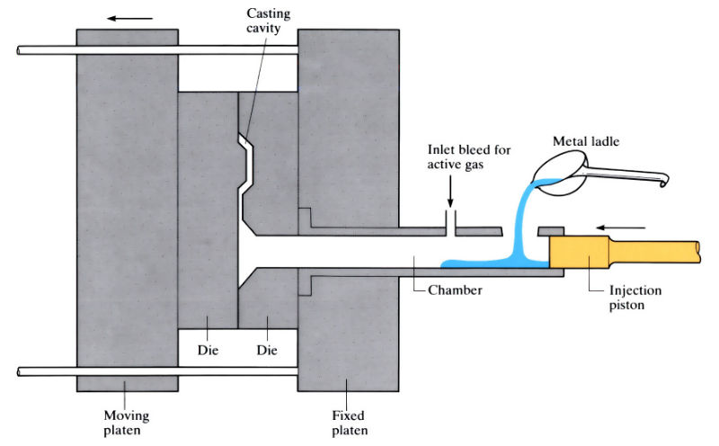
Cold Chamber Machines -- These allow for the metal to be dispensed into the shot sleeve (plunger cylinder) from an outside source. The transfer can be simply with a hand ladle, an automated ladle arm or robot, or via a pump or pressurized holding furnace to achieve an accurate and repeatable mass of metal.
Over the last 20 years or so, the size of die casting machines has increased dramatically to accommodate both heavier and larger castings. The capacity of a machine is defined as the locking force that can be applied to the die platens, and this has now reached over 5,000 tons of force. This allows for larger, thin-walled parts, such as complete door frames to be cast as a single piece.
Hot Chamber (source: fontec-global, LLC)
Hot Chamber Machines -- These, on the other hand, have the holding furnace as an integral part of the die casting machine, and metal is transferred via a pump that is permanently immersed in the metal. A plunger is adjusted to push a defined amount of metal into the die for each cycle.
Because of the limitations of the furnace and immersed pump, this process is confined to smaller die casting machines and parts. Because of aluminum’s aggressive affinity for ferrous metals, this process is more often used for zinc and magnesium casting.
Vertical High Pressure Machines -- These use a similar technology to conventional horizontal machines, but the shot sleeve is vertical and is filled completely in a vertical orientation before injection, allowing a less turbulent flow of metal into the die.
Vertical machines can also use a vacuum and siphon tube system to fill the shot sleeve where the metal is sucked from the holding furnace by a vacuum in the die cavity. Like the low pressure process, it has the advantage of creating a smooth metal flow into the die while the vacuum, strong enough to suck the metal, has the added advantage of a partial degassing effect and gives better quality castings.
There are variations of High Pressure Die Casting that generally have well defined niche markets:
Semi-solid casting, also known as Thixotropic or Rheocasting, uses a similar machine; but instead of molten metal, a billet of semi-solid metal is inserted into the shot sleeve before injection into the die.
The process uses a property of aluminum alloys to be solidified in a way that retains approximately 40-60% liquid, is stable enough to be handled, but can be cut with a knife. The advantage of this process is in creating a casting with similar properties to a forging that can be heat treated and polished. The downside has been the overall cost compared to conventional castings.
Metal powder injection uses fine metal powders with a binder material instead of molten metal, and is poured into the shot sleeve in measured amounts and then introduced into the die and compacted by the plunger. The part is then sintered to remove the binder and consolidate the part. This is used for small and intricate parts where very specific alloy mixes can be created without having to melt an alloy. The process is also used for some magnesium parts overcoming the dangers associated with processing molten magnesium.
Low Pressure Die Casting (LP casting) -- This is used almost exclusively for aluminum road wheels as well as other high integrity and safety critical parts where heat treatment is also a prerequisite to achieve mechanical properties; in this process, the molten metal is forced into the die cavity by pressure in the holding furnace below the die, which raises the molten metal into the die where it is held until the narrow inlet area solidifies and the pressure is released. The smooth flow characteristics provide a high quality casting that can be heat treated.
Gravity (Permanent Mold) Die Casting is maybe the simplest of the die casting processes and can vary from a simple mold for lead shot or fishing where the molten metal is poured directly into either static or tilting molds and flows by gravity into the cavity.
Static molds are filled directly by hand or auto ladle into a split metal die. After solidification, the die is opened and the casting, with runner system, are removed.
Tilting dies are mounted on a tilting mechanism, and the metal is poured into a tundish attached to the die. After filling, the die is tilted to allow the metal to run from the tundish into the die cavity. This enables large castings to be made as the tundish can be filled fully before tilting. Castings of 100 to 300 lbs. are not uncommon, and the limit is normally the size of the die block.
An advantage of this process is the ability to use sand cores to create hollow internal shapes in castings. In gravity and low pressure die casting, the metal flow is gentle enough that sand cores can be used without breaking up and producing hard inclusions in the casting. In HPDC, the speed and turbulence of the metal entering the die is violent enough to break conventional sand cores. There are some foundries using salt cores, which are much harder, and must be dissolved from the casting. They can also create corrosion problems if not done correctly.
Centrifugal casting is used primarily in the casting of pipes and tubes in a variety of ferrous and nonferrous alloys. Molten metal is poured into a spinning tubular mold where centrifugal forces force it into an even coating on the wall of the mold, which is then cooled to create the pipe. The process is predominantly for ductile iron water distribution piping as well as engineering pipe and tube stock.
There are two basic processes used industrially--horizontally spun molds and vertically spun molds.
The horizontal process is used for longer pipes--up to 6 m (20 ft) long--with molten metal being introduced simply at one end and allowed to flow or progress along the mold length (DeLavaud process) to provide a more accurate wall thickness in the finished pipe.
The vertical process is used for smaller cylindrical parts, such as brake drums and other parts where a more dense, defect free metal structure is required. The process is confined to simpler geometries where no or simple cores can be used. Brake drums and discs would be typical parts in grey cast iron.
Direct Chill Cast Billets (source: fontec-global, LLC)
Continuous casting is a process used to continuously cast various alloys into billets, Direct Chill Casting (DCC), for further processing such as for extrusion, or to provide a continuous supply of form to be cut off and processed. The molten metal is poured into a tundish, which provides a continuous and controlled flow of metal into a water-cooled die, which moves up and down as the metal solidifies and keeps the solid metal moving downwards, making more room for new metal being poured.
Slush casting is not such a common process and is used where a hollow part is required with simple geometry and a hollow shape without the use of cores. Molten metal is poured into a mold and given enough time for a solid skin to form before any excess metal is poured out of the mold. The result is a hollow casting. Used traditionally in the art world for hollow sculptures, decorative pieces, etc., it can be used with most alloys but more often with pewter and precious metals.
Counter pressure casting (CPC) uses two separate pressure chambers, creating pressure in the holding furnace above the metal surface while equalizing this with a vacuum above the furnace and in the mold cavity. The result is to draw the molten metal into the mold cavity with the minimum of disturbance and turbulence, thus ensuring a sound casting. The metal is encouraged to solidify with water or air cooling at the in-gate area before pressures are released.
Terminology – some common terms used in the foundry industry:
- Die or Mold: the main component of die casting. The terms can vary depending on location and industry.
- Clamping force: the force exerted between the two halves of the die (the platens), which resist the hydrostatic force from the metal entering the cavity at high pressure.
- Platen: the main carrying plate on the die casting machine to which one half of the die is attached.
- Ram: the piston or plunger that is used to force the metal into the die.
- Tundish: a simple bowl arrangement that allows for metal to be accumulated before or during a casting process.
- Cores: used to create internal cavities in castings. They can be re-useable mechanical components of the die, or more often in LP and gravity they will be expendable pieces made from a resin-bonded sand.
- Holding furnace: used to hold the metal at the chosen casting temperature during casting operations. This is refilled periodically to maintain consistent production.
- Shot sleeve: connected to one half of the die and allows metal to be introduced and held prior to being injected into the die.
- Gooseneck: named for its similarity to a goose's neck, this is the pump unit that sits in the metal and supplies metal in a hot chamber machine.
Die Casting Defects – some terms that refer to common defects on die castings:
- Mis-Runs: where the metal has failed to completely fill the die cavity.
- Porosity: internal voids created by gas trapment or evolution during the solidifying process.
- Blow holes: produced as a result of moisture or contamination on the die or core surface when metal is introduced and caused by the rapid expansion of moisture.
- Inclusions: foreign matter that has become trapped in the casting, such as core sand, oxide particles, etc.
- Hot tears: when the casting strength is insufficient to withstand cooling contraction during solidification.
- Cold shuts: created when the metal entering the die is too cold and solidifies prematurely in some positions while metal is still entering the die.
- Die soldering: aluminum has an aggressive appetite for iron, and certain alloys will attack the steel dies even in the short time for die casting injection, creating adhesion of the casting.
- Heat checking: a form of thermal fatigue cracking where temperature cycling at the die surface creates fine cracks that encourage sticking and degrade the surface finish of the casting.
- Shrinkage: found in castings with heavy sections with poor connections to the main feed path of metal. The contraction to the solid state can create shrinkage depressions at the surface or internal voids.
- Laminations: where cold dies allow rapid solidification of a thin skin before final solidification of the main mass.
Roger Jones, FASM–CEO Emeritus, Solar Atmospheres (source: Solar Atmospheres)
Heat Treat Today’s Medical and Heat Treating December 2019 issue featured an article on medical alloys.Heat Treat Today asked Roger Jones, CEO Emeritus of Solar Atmospheres, Inc., to comment on how specialty medical metals are heat treated. These include titanium, niobium, tantalum, nitinol, and copper, to name a few, which in turn are used to create such standard medical devices and equipment as diagnostic guide wires, miniscule screws for implants, complex surgical tools that are operated robotically, and more. Read to see how Roger describes the hot zone and conditions under which medical device alloys are heat treated.
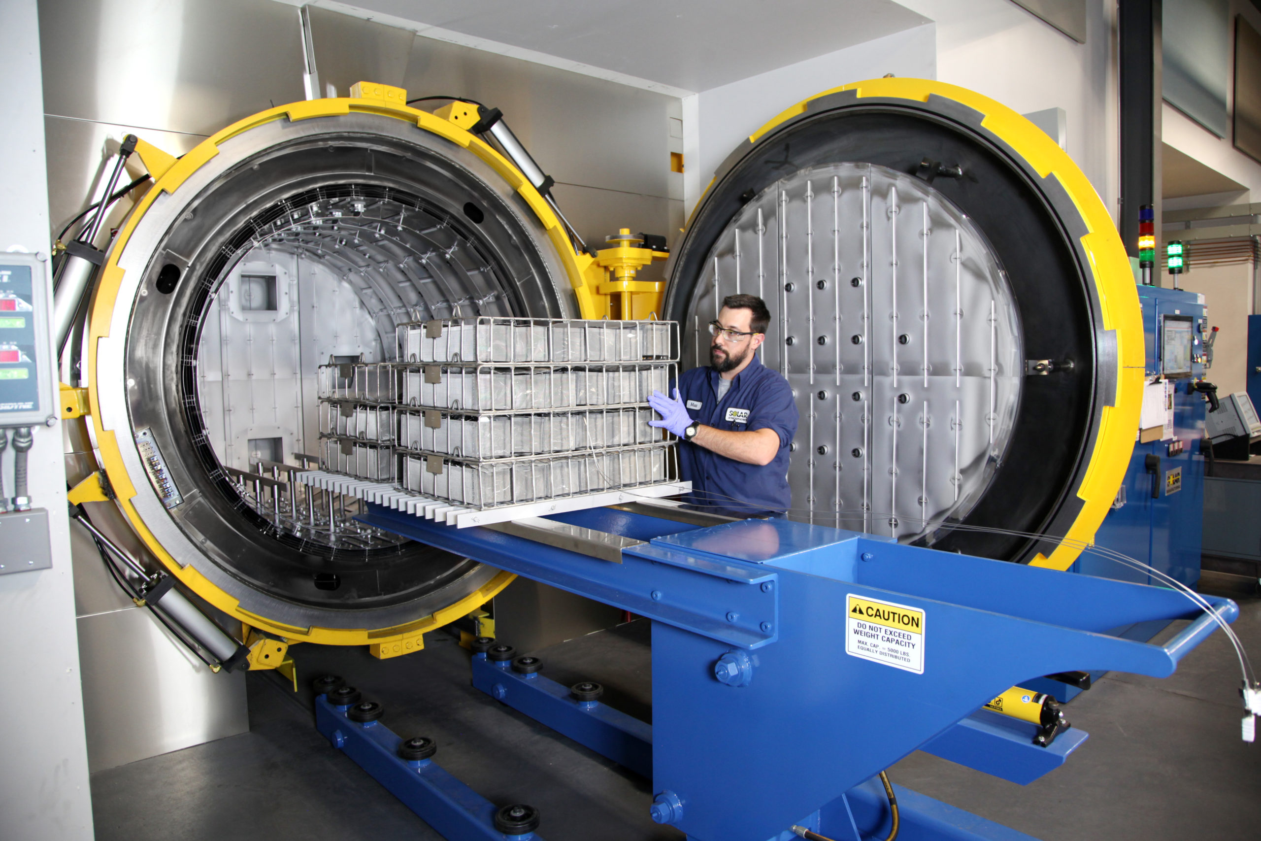
Vacuum furnace chambers processing titanium, niobium, chrome cobalt, and other medical device alloys are typically constructed from stainless steel. The hot zones are comprised entirely of metal (moly); graphite materials are never used in the construction of the hot zone or in fixturing parts. These furnaces process medical device alloys exclusively to avoid cross-contamination of the hot zone or the medical parts being treated.
Ultimate vacuum levels should be 1 X 10⁻⁶ Torr or better, with leak rates no greater than 2 microns Hg per hour. Gas system isolation valves aid in achieving tight vacuum, as they eliminate constant pumping on the quench system. Vacuum furnace leak up procedures are performed weekly, as well as a bake out at 2400 °F for one hour.
Horizontal, front-loading vacuum furnace with all-metal hot zone in a cleanroom setting typically used for heat treatment of medical alloys and devices (source: Solar Atmosphere)
Because of the alloys processed, cooling gases are mainly high purity argon from a liquid source. Very seldom is nitrogen used for cooling. Either type K or type N Inconel clad work thermocouples are imbedded in the loads for precise temperature readouts at +/- 10 °F or better. Processes include vacuum annealing, aging, stress relieving, solution treating, hardening, tempering, and other special processing. All furnaces are approved to the MedAccred quality standard, are surveyed to AMS 2750E, and comply with AS9100D in their processing parameters. Because the alloys are thermally treated, the vacuum furnaces operate in an air conditioned clean room with controlled temperatures and humidity levels.
inTEST Corporation, a global supplier of precision-engineered solutions for use in manufacturing and testing across a wide range of markets including automotive, defense/aerospace, and energy, announced today that its thermal segment subsidiary, Ambrell Corporation, is expanding its applications laboratory capabilities in the United States and Europe.
Ambrell’s applications laboratory, known in the industry as THE LAB at Ambrell (THE LAB), is well known in the induction heating market. With applications laboratory facilities in Rochester, NY, and Hengelo, the Netherlands, Ambrell is expanding its laboratory capabilities to a third location on the west coast. The new lab facility will be located in Fremont, California, specifically to serve customers in the western United States and will include hands-on demonstrations and parts testing of a variety of induction heating applications.
(source: the Wall Street Transcript)
“Customers turn to THE LAB at Ambrell to explore the precision induction heating solutions required to solve their unique heating challenges,” said Jim Pelrin, President and CEO of inTEST. “Our applications laboratory expansion project in Hengelo and California embodies the partnership, collaboration and continued commitment to strengthen the support we provide to our global customer base.”
Scott Nolen, Ambrell’s Vice President and General Manager, added, “Under the direction of Dr. Girish Dahake in the United States and Frank Kuster in Europe, THE LAB at Ambrell now offers an expanded geographical reach and provides state-of-the-art laboratory equipment to deliver innovative and effective heating solutions for the most challenging applications. As a leader in the industry, we’re very excited to announce these important, value-added capabilities to existing and prospective customers worldwide.”
Welcome to another episode of Heat Treat Radio, a periodic podcast where Heat Treat Radio host, Doug Glenn, discusses cutting-edge topics with industry-leading personalities. Below, you can either listen to the podcast by clicking on the audio play button, or you can read an edited version of the transcript. To see a complete list of other Heat Treat Radio episodes, click here.
Audio: Heat Treat Modeling With Justin Sims
In this conversation, Heat Treat Radio host, Doug Glenn, interviews Justin Sims of DANTE Solutions about heat treat modeling. As the heat treat world moves farther way from mysterious black box processes, find out how the latest advances in heat treat simulation software can help your company model specific processes and materials in advance, leading to less guesswork and more profit.
Click the play button below to listen.
Transcript: Heat Treat Modeling With Justin Sims
The following transcript has been edited for your reading enjoyment.
We're going to talk to Justin Sims, lead engineer at DANTE Solutions, Inc., about heat treat modeling. It's a pretty interesting topic. With all the advances and sensors and computing power, the heat treat world is moving further and further away from the mysterious black box processes of yesteryear and is allowing companies to model specific processes and specific materials in advance so that there is less guesswork and more profit. DANTE provides the means by which companies can accurately predict what is going to happen to their part during the heat treat process.
DG: Justin is not only the lead engineer at DANTE Solutions, he is also the author of an article that just appeared in the March 2020 issue of Heat Treat Today and the title of the article wasProcess Innovation To Reduce Distortion During Gas Quenching. It was a pretty interesting article, something worth reading if you haven't already. It has to do with DANTE controlled gas quench.
JS: I got my bachelors in mechanical engineering degree from Cleveland State. I graduated back in 2015. I actually started interning at DANTE in 2014 and went full-time in 2016. I've been the lead/principal engineer at DANTE with mainly responsibilities of managing projects, training our DANTE users, and offering support to our DANTE users. I helped develop our patent-pending DANTE controlled gas quenching process, which you had just mentioned, and then also a little bit of IT, marketing, sales, and shipping. Being a smaller company, we can kind of do it all.
Fig. 1: Bevel gear axial distortion comparison for an oil quench, high pressure gas quench, and a DANTE Controlled Gas Quench
DG: Tell us briefly about DANTE.
JS: DANTE Solutions is an engineering consulting and software company. We offer consulting services as well as licensing our software. We mainly focus on the aerospace industry, the auto industry quite a bit as well, and we've been starting to get into the mining and energy sectors also. As I said, we are a smaller company. There are six of us right now. Two to three guys mainly focus on the software side, and the rest of us focus on more of the training, the support, and the consulting side of the business.
DG: DANTE is located near Cleveland, OH, and Lynn Ferguson, who has been in the heat treat industry for many, many years, was one of the founders. Let's talk about the genesis of the software. Would you say the software is the core product that DANTE Solutions offers?
JS: Yes, it is. We mainly stay in consulting to stay current and to give those users who don't have the capability to run our software (either they don't have the hardware or they don't have the analysts to be able to do such a thing), so we still offer our consulting services for them. But mainly, software is our main line of business. DANTE was actually formed back in 1982 as Deformation Control Technology, Inc., and we changed our name in 2014 to actually reflect more of the software side, so that's when we changed to DANTE Solutions, Inc.
The project itself that DANTE came out of actually started in 1994 and 1995. It was a collaboration between Ford, GM, Eaton Corp. and then four national labs--I believe they were Los Alamos, Sandia, Oak Ridge, and Lawrence Livermore--and then us as Deformation Control Technology. The whole project came out because those large automakers were claiming millions of dollars of lost scrap from distortion. It was starting to become a major issue and they wanted a way to be able to model the process and be able to optimize the process a little bit better. After that project ended, DANTE somehow ended up with the software, which has worked out well, as we've been able to commercialize it and we've been updating all the material models and the material database for the last 20 years. It's actually come quite a long way.
DG: How did you segue over from auto industry into aerospace?
JS: It just happens that the aerospace components cost a whole lot more than the auto industry components. It was a natural fit once they realized that this software was viable and could do what they needed it to do. And aerospace seems to be more receptive to modeling because their parts are so expensive.
DG: Let's try to put a little flesh on the bones here. For a manufacturer who has their own in-house heat treat for aerospace, automotive, energy or whatever, what makes this software attractive? What makes it viable? Why would someone want it, and why and how do they use it?
JS: Let's start with viability. The first thing is that it is easy to use. DANTE is a set of material routines that link with Abaqus or Ansys finite element solvers. These are solvers that engineers and analysts in the industry already know pretty well, so there is not a lot of learning of new software. DANTE is just a material model, so all you're really responsible for is the material name and what microstructural phases you're starting with. Then we have the ability to modify a few of our control parameters, activating different models; we've introduced stress relaxation, carbon separation, carbide dissolution, and all these different models that you can activate. But the biggest thing that trips people up . . . [is] understanding your process. We like to work with people a lot on trying to help them understand what type of thermal behavior their processes are actually imparting on components. We've done a lot of work with setting up their essentially quench probes and be able to turn around and be able to take that back to heat transfer coefficients that get put into the model. As far as DANTE is concerned, it is fairly easy to use.
We've also developed what they're calling ACT (Ansys Customization Toolkit). It is essentially a series of buttons where you would click on these buttons, fill out information, and then essentially run your models. Abaqus, for the new version of DANTE, we've also developed a plug-in that essentially does the same thing. So DANTE has become very point-and-click. In this world, I think people like that simplicity.
Fig. 2: Axial distortion of a press quenched bevel gear
The next big one would be the accuracy that everybody is concerned about. Our accuracy is due to the models that we use and the algorithms that we employ. There are two types of accuracy. I've touched on the boundary condition accuracy, and that is how your process behaves thermally. That accuracy can be tough to get. It's very doable and we've helped people achieve some really amazing accuracy. The relationship I like to use here is people know static loading models and a lot of engineers have run static loading models. The loads that you put on these static models are going to determine what deflections you get. If your load is not correct, then your deflection will not be correct. In heat treat modeling, the thermal boundary condition is your load. The more accurate your heat transfer coefficient can be, the more accurate your results are. But, with that being said, you can still gain a lot of valuable information from being close enough. We'll talk a little bit about that with the uses and whatnot.
The first important model type that we use is the mechanical model. We use a multiphase internal state variable model. A conventional plasticity model considers stress as a function of strain only, where the internal state variable model actually accounts for the history of deformation by relating the stress to dislocation density. It actually accounts for the history of deformation, which is very important as the steel goes through all the stress reversals that it does going through the process. Our mechanical model defines each phase, so austinite, pearlite, ferrite, bainites martensite, tempered martensite, all of them, as a function of carbon, temperature, strain and strain rate. It also accounts for the trip phenomenon.
For our phase transformation model, we like to use analytical models instead of TTT CCT diagrams, and we do this because you don't get any transformation strain information out of the diagram. So you have no idea how much it is deforming. In order to figure that out, we like to use dilatometry tests to fit to our analytical models. We also account for carbide growth and dissolution during carburizing, which is becoming a major point of interest due to the high alloy content of some of these steels that they're now trying to carburize.
DG: Let's talk a bit more about where manufacturers, who have their own in-house heat treat, might use DANTE's software tool.
JS: One of the big things we like to use it for is what we call sensitivity analysis. This would be, "what happens if my normal process has a little bit of variation?" Or, "what happens if my process parameters change a little bit?" We've also worked into the model now normal material variation. So if your alloy content is a little on the high side, how would the material behave? If it's a little on the low side, how will it behave? [This] is a big deal. One example would be, "I just designed a new part and I want to make sure that it behaves given the range that I know my process can vary." All processes will vary. This is no way to make the process exactly the same every time. Also, in the sensitivity, you can ask the question, “What process variable is a distortion or stress most sensitive to?" By finding out what process variables cause the most sensitivity, then those are the process variables you really need to pay attention to during processing, then the other ones you can just make sure they're in range and leave them alone.
Development and design are two of the big ones that we're trying to get out there that this software can be used for. Everybody knows that it can be used for troubleshooting. Once something goes wrong, yes, sure the software is great and we help figure out a problem; but why not find the problem before it ever even happens? We've been trying to get people to use it for development of new carburizing and nitriding schedules as well as new recipe and design, and even novel processes. You had mentioned our DANTE controlled gas quench. That actually was conceived through all the modeling that we do and watching the response of the material and saying, “Wait a second. If we can control the martensite transformation rate, we can really control the distortion, so let's see if we can do this.” Things like that can come out of the software. Design as well, of optimizing shapes for quench. You can even do quench to fit, which is, "I know my part distorts this much, so let me machine it distorted and then it will fall into shape." Optimizing processes. All of that can be done through design development, and you can find these problems before they ever happen.
Another really big one that I like, and Lynn, our owner, is really keen on this one, is the understanding of your process. When you start to set up these models, you have to ask a lot of questions about your process. What is the HTC of my process, which relates back to agitation in the tanks, part racking, flow directions? You really need to know times and temperatures of every step in your process. So not just the heat to quench, but what about all those transfers in between? All of that needs to be done. So you end up asking a lot of questions like that.
The other one that I always like to say is that the heat treat software removes the black box. In the past, you know what goes in and you know what comes out, but what happens in the middle is kind of a mystery. The software helps you figure out what exactly goes on during your process. It can be very eye-opening.
Fig. 3: Minimum Principal stress of a carburized and oil quenched spur gear
DG: I've talked with James Jan and Andrew Martin over at AVL, and we talked about a variety of ways they use some of their software, and they mentioned that they work with you guys as well, and they were talking about not even just like a quench agitation, flow direction, and things of that sort, but part orientation as it goes into a quench. I assume that would be something also that you guys would be able to help analyze, right? Which way to even put the part into the quench?
JS: Sure, sure. And we've done that. The one that comes to mind is a long landing gear. This landing gear was about 3 meters in length, and we looked at even slight angles going into the quench tank can have serious consequences on the distortion. That is definitely something that we've looked at in the past.
DG: Just that orientation would help, but maybe eliminate vapor stage, or whatever, I assume? Or pockets?
JS: Right. And even beyond that, it sets up thermal gradients in different locations of the part. So now instead of cooling one section faster, you're cooling it a little slower and that kind of thing. That also relates back to actual vapor stages and how bubbles get trapped. But that goes back to defining boundary conditions, which is where software like AVL's FIRE can really be helpful in understanding flow patterns. There is a beneficial relationship there.
DG: There are a host of different materials that people are using. How broad is the database, as far as the different types of materials, that you can analyze and model?
JS: That is a good question. We have a lot of low alloy, medium alloy, and carburizing grades of steel, the 1000 series, the 8600 series, 9300 series, those types of materials. We've also worked with some of the high alloy aerospace grades like C64 and the Pyrowear 53 and that sort of thing. But right now, it's all steel. There is a lot of talk about being able to do aluminum. We get that question a lot.
DG: I was wondering about that specifically- aluminum and/or of course, when we talk aerospace, we're talking titanium. So titanium is not on the table at the moment?
JS: It is, but it isn't. The interesting thing is that there is a phenomena precipitation hardening that goes on in aluminum and titanium. But it also goes on in these high alloy steels. It is a secondary hardening mechanism. We've been working on that and we feel that once we can handle secondary hardening in steel, then the jump to aluminum and titanium should be pretty straightforward.
DG: So to recap, for those of us who are not as well-versed in the product as you are, basically you've got a simulation software that takes into account the material that is being used, also the thermal process (the recipe), which would include both a controlled heat up and potentially a controlled quench. Is that a reasonable way to describe it in a very broad way?
JS: Yes. And also, even the steps before that, like carburizing. If the part is carburized, you would carburize it first. Or nitriding; we've just introduced those models. You can literally do the entire process. And it's not just quenching either. We've done martempering, austempering, normalizing, all of these things. Most all normal thermal processing, DANTE can handle.
DG: The last question I want to ask is, Who is the ideal person/company that would really find the product/service that you're providing useful? I know you mentioned aerospace and automotive, but can we be more specific than that? Where are you finding the most success?
Fig. 4: Displacement versus temperature curves showing the shift in martensite start temperature for 3 carbon levels
JS: That's a tough question. Generally, everybody that has used our software has found real benefit in it. We've tried to get testimonials from a lot of folks, but this can be difficult because of their companies. But from Cummins, we've gotten good responses and also from GM we've gotten good responses. One of them has used it to actually introduce new material and replace legacy material that is now saving them quite a bit of money. GM has used it to look at process design and optimization. But I would say mainly the people that are going to benefit the most are the folks that have an analyst to be able to do the simulation almost on a daily basis. It's one of those things where the more you do, the more you see and the more you understand what is happening. But really anybody that does heat treatment can benefit from understanding what's going on in their process.
DG: You mentioned Cummins, and I'm looking at your website, and I just want to read a paragraph:
DANTE heat treat simulation software has been a great boon to Cummins. Since we've started using their software, we have gone through several projects that have increased our understanding of heat treatment and some of which have saved us production costs. One example was enabling us to gain the leverage needed to make a material and process change on a legacy product that is now saving us at least 25% on material costs. The team at DANTE Solutions has always been very accommodating and is very quick to give assistance and feedback whenever troubles arise, even when the troubles are caused by other parts of the simulation and not DANTE itself. I look forward to working with DANTE team in the coming years as we expand our list of engineers who use this software. -- Brian W. at Cummins
So that leads me to one other question. When a person interacts with you, are they buying software as a service? Is it cloud-based or is it something that they purchase a license for one computer, one user? How does it work?
JS: There are a couple of different ways. They can lease it annually or they can essentially buy the software and lease a license annually. The software can go either on their computer or it can go on a server at their company. We also have options for corporations where you can essentially get software at different locations. We have a lot of options and we can work with customers if they [have] unique needs. That's one of the benefits of being a smaller company, we're pretty flexible like that.
DG: DANTE's mission statement from their website has a nice ring to it: “DANTE Solutions is determined to promote the use of simulation in the heat treat industry. From design to troubleshooting, DANTE Solutions believes everyone can benefit from a little simulation in their life.”
If you'd like to get in touch with Justin Sims at DANTE, please email me, Doug Glenn, directly at doug@heattreattoday.com and I'll put you in touch with Justin.
Doug Glenn, Heat Treat Today publisher and Heat Treat Radio host.
To find other Heat Treat Radio episodes, go to www.heattreattoday.com/radio and look in the list of Heat Treat Radio episodes listed.
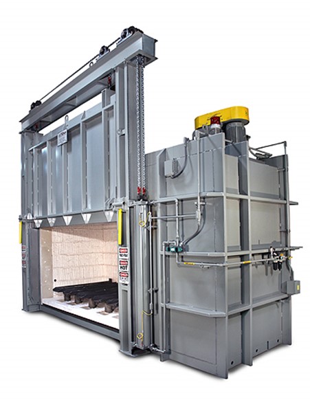
A commercial heat treating company located in the heart of the aerospace industry on the West Coast of the United States recently commissioned a custom built batch tempering furnace. With a working load size of 168” wide, 48” deep, and 48” tall, coupled with a max load weight of 10,000 pounds, the furnace from Gasbarre Thermal Processing Systems can accommodate a number of differently sized parts within its market.
The gas fired air furnace passes survey at +/- 10℉ over a temperature range of 850℉ to 1350℉ per AMS2750E. At the customer’s request, the electrical controls are UL approved and include the latest in Eurotherm brand temperature controlling instrumentation.
Have you ever wondered how to create or revise AMS specifications? In this original Heat Treat Today Technical Tuesday feature, come along with Andrew Bassett, president of Aerospace Testing and Pyrometry and an expert in aerospace pyrometry specifications, as he shares his experience and knowledge in the process.
Andrew Bassett, President, Aerospace Testing and Pyrometry
Author’s Note: These comments are the non-binding opinion of the author and do not constitute an interpretation by SAE. Such opinions do not replace the need to ensure agreement between the supplier, customer, and cognizant engineering organization.
Those who are familiar with aerospace heat treating are accustomed to Aerospace Material Specifications (AMS) that guide heat treaters on how to process parts and raw materials. These specifications will mandate equipment requirements, atmospheres to be used, cleaning methods, soaking times and temperatures, and testing requirements, to name a few. The working committee, Aerospace Metals Engineering Committee (AMEC), is in charge of revising these specifications, which is required every five years. This is a long and sometimes tedious process of revising specifications with many knowledgeable experts involved.
There are various types of specifications that have been established by the SAE Technical Standards Board:
Aerospace Material Specifications (AMS)
These technical reports contain specific performance requirements and are used for material and process specifications conforming to sound established engineering and metallurgical practices in aerospace sciences and practices.
Aerospace Standards (AS)
These technical reports contain specific performance requirements and are used for design standards, parts standards, minimum performance standards, quality, and other areas conforming to broadly accepted engineering practices or specifications for a material, product, process, procedure, or test method.
Aerospace Recommended Practice (ARP)
These aerospace technical reports are documentations of practice, procedures, and technology that are intended as guides to standard engineering practices. Their content may be more general in nature, or they may offer data that has not yet gained broad acceptance.
Aerospace Information Report (AIR)
These aerospace technical reports are compilations of engineering reference data, historical information, or educational material useful to the technical community.
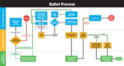
To create or revise an Aerospace Specification, a “sponsor” of the specification will request to either create a new or revise an existing standard with the approval of the chairperson. Once the approval has been granted, the sponsor will work to create and/or revise the existing document. When the draft document is complete, the draft is balloted for a 28 Day Ballot. Members of AMEC can make comments on the ballot with either a “T” comment or an “I” comment. The “T” comment is a technical error, missing requirement, or improper requirement that needs action by the committee. All technical comments should be accompanied by a reason for the comment and a suggested improvement to resolve the issue. The “I” comment is a non-technical correction. These may include spelling and grammatical mistakes, incorrect paragraph numbering, and the like. Each “T” comment must be discussed and voted on by the committee members and approved or disapproved. During the ballot process, members are asked to “Approve” or “Disapprove” the ballot. This process goes on until no more changes are required to the draft before the document is sent to the appropriate commodity committees.
The illustration (Figure 1) describes the creation/revision process for given specifications.
The projects for the revisions to AMS-2759 series of specifications started in 2009/2010 with many of the draft revisions waiting in “parking lots” until all the specifications were completed. Since their release in 2018, several of these specifications had to be revised again due to missing or omitted requirements or small changes to clarify issues.
Over the last eighteen months, the heat treat industry has experienced new revisions to the following specifications (revision dates):
AMS-2759 Rev G Heat Treatment of Steel Parts General Requirements (04-23-19)
AMS-2759/1 Rev H Heat Treatment of Carbon and Low Alloy Steel Parts Minimum Tensile Strength Below 220 ksi (1517MPa) (09-19-19)
AMS-2759/2 Rev J Heat Treatment of Low Alloy Steel Parts Minimum Tensile Strength 220 ksi (1517MPa) and Higher (07-15-19)
AMS-2759/3 Rev H Heat Treatment Precipitation-Hardening Corrosion-Resistant, Maraging and Secondary Hardening Steel Parts (01/07/19)
AMS-2759/4 Rev D Heat Treatment Austenitic Corrosion-Resistant Steel Parts (04-28-18)
AMS-2759/5 Rev E Heat Treatment Martensitic Corrosion-Resistant Steel Parts (04-28-18)
AMS-2759/6 Rev C Gas Nitriding of Low Alloy Steel Parts (06-11-18)
AMS-2759/7 Rev D Carburizing and Heat Treatment of Carburizing Grade Steel Parts (04-15-19)
AMS-2759/8 Rev B Ion Nitriding (06-11-18)
AMS-2759/9 Rev E Hydrogen Embrittlement Relief (Baking) of Steel Parts (10-18-18)
AMS-2759/10 Rev B Automated Gaseous Nitriding Controlled by Nitriding Potential (06-11-18)
AMS-2759/11 Rev A Stress Relief of Steel Parts (04-28-18)
AMS-2759/12 Rev B Automated Gaseous Nitrocarburizing Controlled by Potentials (07-02-18)
AMS-2759/13 Gaseous Nitrocarburizing (06-11-18)
AMS-2769 Rev C Heat Treatment of Parts in Vacuum (07-12-19)
AMS-2770 Rev P Heat Treatment of Wrought Aluminum Alloy Parts (04-08-19)
ARP-1962 Rev B Training and Approval of Heat Treating Personnel (06-11-19)
ARP-7446 Vacuum Gauge Calibration (03-06-19) New ARP
There are several more projects underway that include the revision of AMS-H-6875, Heat Treatment of Steel Raw Materials that will become a four-digit AMS Specification, AMS-2774, Heat Treatment Wrought Nickel Alloy and Cobalt Alloy Parts, AMS-2801, Heat Treatment of Titanium Alloy Parts and AMS-2750, Pyrometry, to name a few. As new technology emerges, such as additive manufactured metal parts, AMS standards will need to be revised or created to address the thermal processing of these parts.
AMS-2750 (Pyrometry) is one of the more contentious specifications, which is currently under revision, because it is the main specification for the testing of thermal processing equipment. This specification not only has an effect on commercial heat treaters working in aerospace, but this specification has been adopted in chemical processing/coatings for baking/drying ovens, composites for curing and bonding laminates, and as of January 28, 2018, the FDA Center for Devices and Radiological Health has added this standard to its list of recognized consensus standards database. For those who are heat treating medical devices such as needles, heart wires, titanium staples, and metallic joint replacements, AMS-2750 is now governing how the thermal processing equipment will be tested.
When I first became involved with AMEC in June 2008, the AMS-2750D (Pyrometry) was starting to be revised to AMS-2750E. I attended my first meeting in Niagara Falls, New York, with the expectation that I would be working only with a group of aerospace primes who write these standards. As it turned out, many of the members at AMEC are end users, such as captive and commercial heat treaters who are experts in the specifications in which they are involved. Since being in the field of pyrometry, I thought I would volunteer my time and expertise on the revision of AMS-2750. The sub-team group consisted of experts from Boeing, Honeywell, Carpenter Technology, Alcoa, Performance Review Institute (PRI), and Bodycote Thermal Processing with each team member bringing to the table his/her own knowledge and expertise in pyrometry. The process of revising this specification took four years to complete with numerous team meetings to discuss and propose changes to better clarify the previous revision. The final revision was finally published in July of 2012. Since then, I have been involved with other specifications such as AMS-2769 (Heat Treatment of Parts in a Vacuum), ARP-7446 (Vacuum Gauge Calibration), and the next revision of AMS-2750F.
Getting involved with AMEC and the various commodity groups is rewarding as it allows you to have a voice in the specifications that affect your business. You work with other members in the heat treat community to develop and create specification to enhance the industry, better the process, and continually strive to deliver quality parts or materials.
About the Author: Andrew Bassett is the president of Aerospace Testing and Pyrometry and is an expert in aerospace pyrometry specifications. He has 25 years of experience in the calibration and testing of thermal processing equipment. This article originally appeared in Heat Treat Today’s March 2020 Aerospace print edition.
It pays to carefully consider the key factors to buying a vacuum furnace (source: TAV, the Vacuum Furnaces Blog)
When and why is it a good idea to purchase a vacuum furnace? Does your company really need one? A company that wants to play its cards best, in terms of investment and yield, knows about the advantages offered by vacuum heat treatments in both the short and long term. But choosing the ideal furnace best suited to your company’s needs isn’t as easy as it might appear.
In this Heat TreatToday Best of the Web feature, TAV Vacuum Furnaces gives readers a handy guide over at its blog to consider the crucial factors in choosing a vacuum furnace for your company, including tips on who needs a vacuum oven, why comparing two or more systems is a bad idea, and the role of the heat exchanger, vessel performance, and the pumping unit.
An excerpt: “There are many fields, ranging from the vacuum sintering of metal powders or ceramics to the vacuum brazing of aluminum alloys to continue with high temperature brazing, in which technological avant-garde stands out. In these sectors, the decision to use a vacuum furnace is linked to the possibility of implementing an advanced development production process, for which the focus was on high-yield plants.”
Heat Treat Today offers News Chatter, a feature highlighting representative moves, transactions, and kudos from around the industry.
Personnel & Company Chatter
Bill Gornicki was recently appointed Director of Sales at ECM-USA, Inc. in Pleasant Prairie, WI.
AFC-Holcroft, in Wixom, MI, recently moved its European satellite office from Delémont, Switzerland, to Swiebodzin, Poland, as necessitated by the retirement of their Director of European Operations. The new director, Marek Kedzierzynski, will be based out of Poland.
Wire ExpertsGroup, the parent company to Pelican Wire and Rubadue Wire, recently announced the newest members of their leadership team and their respective roles: Brinson White will now lead the Engineering & Maintenance teams at both Pelican and Rubadue as WEG Director of Engineering; Mike Skorupa has been named Director of Continuous Improvement across all business units; and Kevin Clements has been named Global Supply Chain Manager.
RETECH Systems, LLC, a SECO/WARWICK Group company, has finalized plans to relocate its headquarters from Ukiah, CA, to Buffalo, NY.
Charlie Li, of DANTE Solutions, began teaching a new master-level Mechanical Engineering class entitled “Advanced Manufacturing Processes: Heat Treatment of Steels” at Cleveland State University.
Bill Gornicki, Director of Sales, ECM-USA
Brinson White, Director of Engineering, Wire Experts Group.
Mike Skorupa, Director of Continuous Improvement, Wire Experts Group
Kevin Clements, Global Supply Chain Manager, Wire Experts Group
Charlie Li, DANTE Solutions
Marek Kedzierzynski, Director of European Operations, AFC-Holcroft
Equipment Chatter
Solar Atmospheres has purchased two microscopes, one a ZEISS AxioVert A1 Inverted Materials Microscope and the other a a Hitachi smart Scanning Electron Microscope, to enable them to better serve the needs of their customers.
Magnetic Specialties, Inc. recently shipped two 510KVA, three phase step down 6-pulse rectifier transformers and DC inductors for use in industrial rectifier applications.
The Grieve Corporation recently installed their new electrically-heated 2000°F inert atmosphere heavy-duty box furnace to be used for heat treating titanium at a customer’s facility.
Gasbarre Thermal Processing Systems recently commissioned a model CVPQ Continuous Vacuum Furnace with 5 BAR pressure quench capabilities, and a precision gas nitriding and ferritic nitrocarburizing furnace, in the Midwestern United States.
Ipsen USA offers free evaluations of any brand of vacuum heat-treating system in the United States. An Ipsen Customer Service team member will check all major components of the furnace and provide a written health report with a suggested 18-month maintenance plan.
Tenova recently received the official notice to proceed with the new Hot Dip Galvanizing (HDG) line for NLMK Group in Lipetsk, Russia.
Pries Enterprises finished a 50,000 sq ft expansion and installation of a state-of-the-art anodizing line, making them the only vertically integrated extruder-anodizer fabricator in their immediate area.
ZEISS AxioVert A1 Inverted Materials Microscope
A Hitachi smart Scanning Electron Microscope
510KVA, three phase step down 6-pulse rectifier transformer and DC inductor
Inert atmosphere heavy-duty box furnace
Continuous Vacuum Furnace (model CVPQ) with 5 BAR pressure quench capabilities
Precision Gas Nitriding and Ferritic Nitrocarburizing Furnace
Ipsen offers free furnace evaluations
Kudos Chatter
Grupo Mess was recently named an exclusive Buehler distributor of metallographic and hardness equipment in Mexico.
Aerospace Testing & Pyrometry recently announced the opening of their newest regional office in Greenville, SC. The territory will include North Carolina, South Carolina, Virginia, Georgia, Tennessee and Alabama.
Constellium SE was recently recognized with the “Best Performer Award” by Airbus.
Advanced Heat Treat Corp. recently announced that it has added gas nitriding to its Nadcap® accreditation.
Grupo Mess
Heat Treat Today is pleased to join in the announcements of growth and achievement throughout the industry by highlighting them here on our News Chatter page. Please send any information you feel may be of interest to manufacturers with in-house heat treat departments especially in the aerospace, automotive, medical, and energy sectors to editor@heattreattoday.com
A global manufacturer of thermal-processing and sterilizing equipment announced they are working with hospitals to prove the efficacy of their Gruenberg product line for dry heat sterilization on PPE and N95 masks for re-use.
Recent tests at a research hospital show positive results in the dry heat sterilization of masks, face shields, gowns and other PPE, with minimal deterioration of the material. During the process, Thermal Product Solutions, LLC (TPS) heated masks to a specified temperature for a calculated period of time that resulted in sterilization of the material. After the sterilization process, fit tests were performed on the masks that passed filtration efficacy, structural integrity, and mask fit. TPS is continuing to work with facilities to further confirm test results.
Greg Jennings, president and CEO, Thermal Product Systems
“We are dedicated to finding methods that aid in protecting the health and safety of all those serving on the front lines during the COVID-19 pandemic,” said president and CEO Greg Jennings. “Our dry heat sterilizers have been used for decades in the decontamination and sterilization of all forms of microbial life and it only made sense to begin testing their efficacy on sterilizing PPE for hospitals and emergency personnel. We are looking to find additional testing partners quickly and ultimately receive FDA approval to help fight the COVID-19 spread.”
Picture 2: Gruenberg Truck- In Sterilizer (source: Thermal Product Solutions)
The Gruenberg sterilizers utilize convection airflow and dry heat for the process. Heat is absorbed by the item being sterilized for a period of time until it reaches the proper temperature needed to destroy microorganisms and achieve sterilization. Dry heat sterilizers range in size from small tabletop models (Picture 1) starting at 1.25 cubic feet (cf) to large truck-in models (Picture 2) offering 1,000cf of sterilization capacity.
Gruenberg’s smaller dry heat sterilizers feature a unique design where the process chamber is sealed throughout the entire cycle, containing any airborne particulates and sterilizing them. Larger chamber systems are easily customized and feature intake and exhaust HEPA filters and several door seal options.


 When it comes to hardness testing nowadays, the process does not have to be done manually; automation has taken much of the burden away from operators. But which way produces the better result?