FEATURED NEWS

Process Innovation to Reduce Distortion During Gas Quenching

“High-pressure gas quenching (HPGQ) attempts to reduce temperature nonuniformities by reducing the cooling rate; however, this is generally not sufficient to eliminate shape change. Shape change can be predicted by heat treatment simulation software, but it is difficult to reproduce the exact same cooling conditions in the vessel for each batch. Therefore, the distortion of the components will not be consistent from batch to batch.”

Read the case study to see one response to this issue in this original content from Heat Treat Today by Justin Sims, lead engineer at DANTE Solutions.

This article first appeared in the latest edition (March 2020) of Heat Treat Today’s Aerospace Heat Treating magazine.


Distortion is generally described by a size change and a shape change. In heat treatment of steels, size change is unavoidable and is mainly due to the volumetric difference between the starting microstructural phase and the final microstructural phase. Shape change of steel parts from heat treatment is due to nonuniform thermal and nonuniform microstructural strains as a result of nonuniform cooling or heating, alloy segregation, poor support of the component while at high temperature, thermal expansion or contraction restrictions, or residual stresses from prior forming operations. Nonuniform cooling or heating can be as fundamental as the temperature gradient from the part surface to its core, or as complex as the flow of fluid around a component feature. Both can result in nonuniform strains, resulting in a shape change. If the stresses causing these strains exceed the yield strength of the material, then permanent shape change will occur. Size change can be anticipated and is predictable, while shape change, or distortion, is usually unanticipated and more difficult to predict.[1-2] 

Justin Sims,
Lead Engineer,
DANTE Solutions

Most thermal processes try to control these nonuniformities using methods of low complexity such as part orientation and rack design. Quenching systems, for example, are generally designed to remove as much thermal energy from the work pieces as possible and to do this as quickly as possible. High-pressure gas quenching (HPGQ) attempts to reduce temperature nonuniformities by reducing the cooling rate; however, this is generally not sufficient to eliminate shape change. Shape change can be predicted by heat treatment simulation software, but it is difficult to reproduce the exact same cooling conditions in the vessel for each batch. Therefore, the distortion of the components will not be consistent from batch to batch.

In response to this issue, a prototype gas quenching unit capable of controlling the temperature of the quench gas entering the quench chamber was devised. With the DANTE Controlled Gas Quench (DCGQ) unit, it is possible to have control of the thermal and transformation gradients in the component by controlling the temperature of the incoming quench gas, thereby significantly reducing, or eliminating entirely, the shape change caused by quenching. In doing so, the size change can easily be predicted by heat treatment simulation software, and post-hardening finishing operations can be reduced or eliminated. This process is ideal for thin parts or components with significant cross-sectional changes. Atmosphere Engineering (now part of United Process Controls) in Milwaukee, Wisconsin constructed the unit and provided the logic to control it. All experiments with the unit were conducted at Akron Steel Treating Company in Akron, Ohio. The project was funded by the U.S. Army Defense Directorate (ADD).

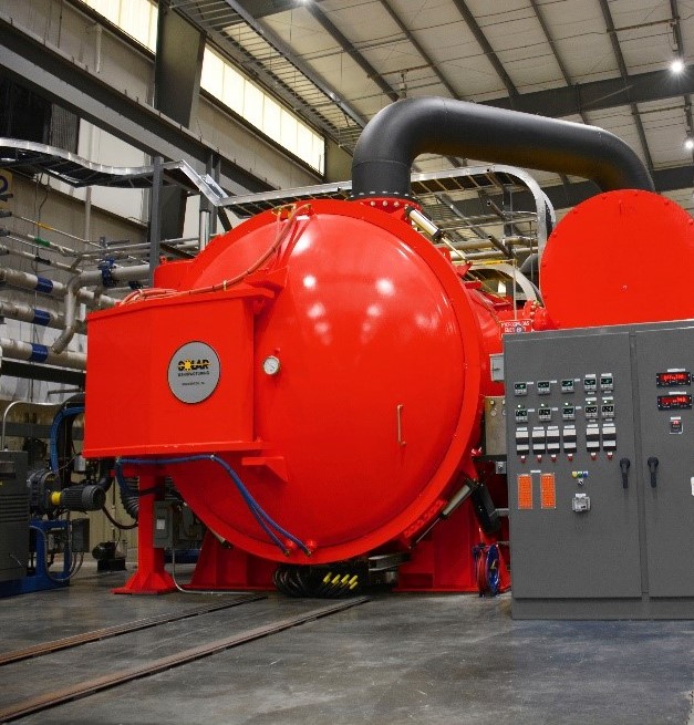
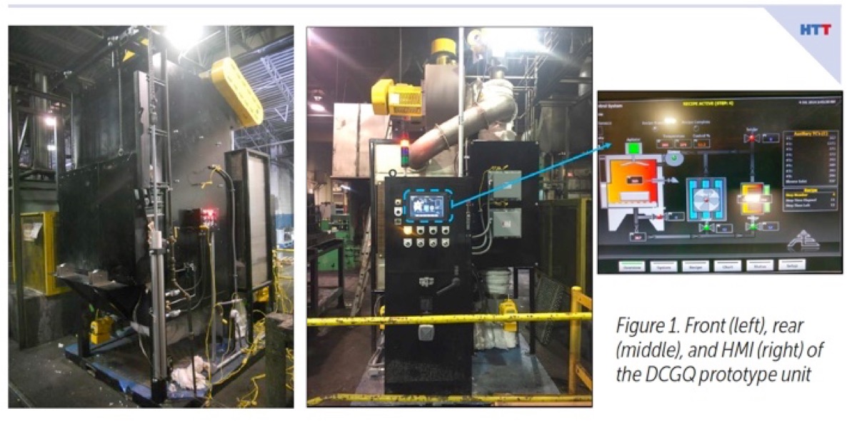
Figure 1 (left) shows the front of the unit, while Figure 1 (middle) shows the back of the unit. The back of the unit contains the human machine interface (HMI), shown in Figure 1 (right), where process parameters can be modified and DCGQ recipes entered. The prototype unit has a working zone of nine cubic ft. and is capable of quenching loads up to 100 lbs. at one atmosphere of pressure.

Figure 2. Comparison of quench gas temperature entering the
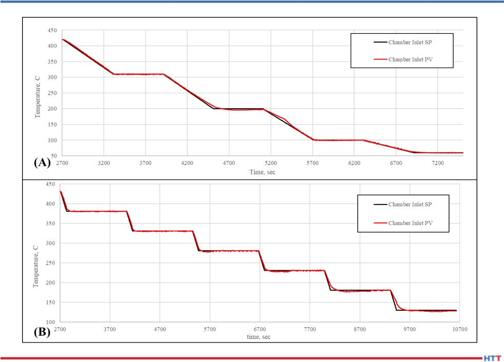
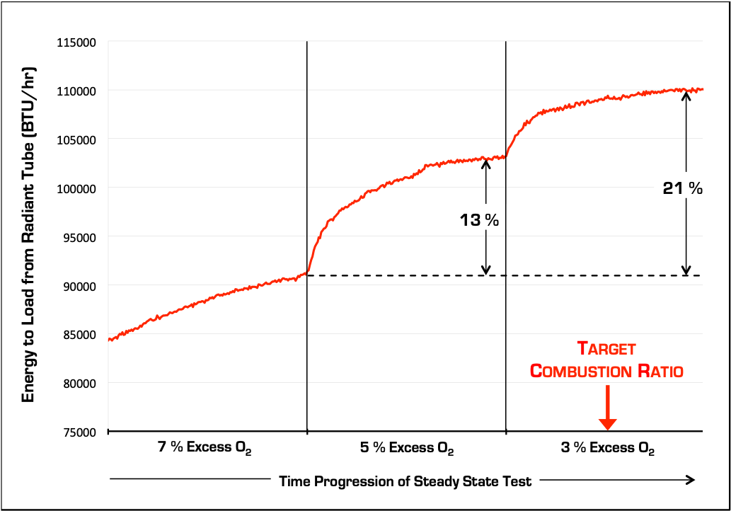
quench chamber versus the recipe setpoint temperature for
two different DCGQ process recipes

The ability of the unit to maintain continuity between the recipe setpoint temperature and the actual temperature entering the quench chamber is absolutely paramount. Figure 2 shows two schedules, one aggressive and one conservative, comparing the recipe setpoint (Chamber Inlet SP) to the actual quench gas temperature (Chamber Inlet PV). Figure 2 also shows that the prototype unit has good control of the quench gas temperature between 752°F (400°C) and room temperature, the martensite transformation range for most high hardenable steel alloys. There is some deviation between the two temperatures below 392°F (200°C) for the aggressive schedule as the setpoint reaches its set temperature, due to the relatively small temperature difference between the quench gas and the shop air. This small temperature difference makes it slightly difficult for the air-to-air heat exchanger used in the design to keep up with the rapid drop in temperature, but overall there is very good control of the quench gas temperature.

Figure 3. Micrograph of DCGQ (left) and HPGQ (right) processed coupons, mag. 1000X
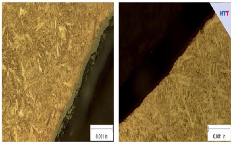
There is a copper layer on the surface of the DCGQ processed coupon.

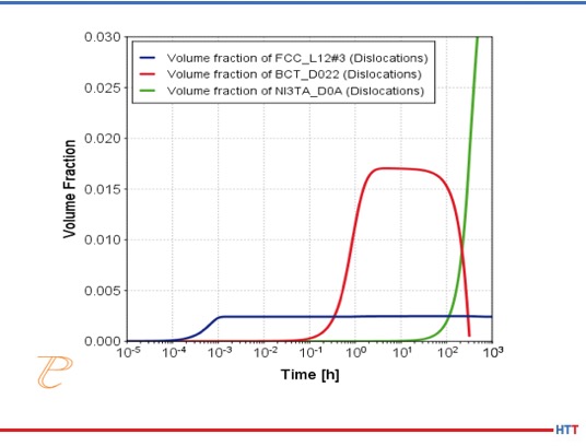
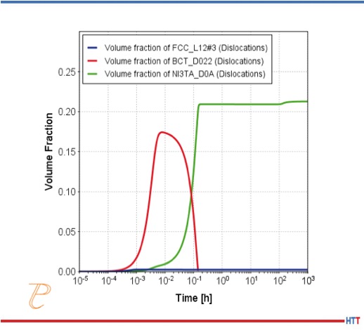
Microstructural examination was conducted on Ferrium C64 coupons processed using the DCGQ process and coupons processedusing a 2-bar HPGQ. C64 was chosen for this study due to its extremely high hardenability and its high tempering temperature. Figure 3 compares the microstructures of the two processes at a magnification of 1000X, and no significant difference is detected. The DCGQ coupons required two hours to complete the transformation, whereas the HPGQ coupons transformed in a few minutes. There is no indication that the slow rate of transformation damaged the microstructure or mechanical properties in any way. Tensile and Charpy properties were equivalent between the two processes.

Distortion coupons, thick disks with eccentric bores, were designed and manufactured with the goal of evaluating the distortion response when subjected to a DCGQ process, and then compared to coupons subjected to a standard 2-bar HPGQ operation. All coupons were manufactured from the same Ferrium C64 bar stock. All coupons were cryogenically treated and tempered at 595°C for eight hours after quenching.

Figure 4. Nomenclature and locations used for out-of-round measurements on the distortion coupon

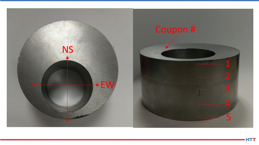
Figure 4 shows a distortion coupon with the nomenclature and locations used for measuring the out-of-round distortion of the eccentric bore. Due to the uneven mass distribution, the north-south direction will generally be larger than the east-west direction. Five measurements were then made along the axis of the coupon using a Fowler Bore Gauge.

Table 1. Out-of-round distortion measurements of the distortion coupon for a DCGQ and HPGQ process

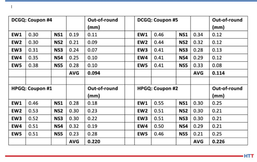
Table 1 shows the results from four coupons; two hardened using the DCGQ process and two processed using the standard 2 bar HPGQ for C64. The individual measurements (EW1, NS5, etc.) are relative and are dependent on the reference value used for the bore gauge. The individual measurements give an indication of the variation in distortion in the axial direction. The out-of-round measurements are actual values, as they are the difference between the actual measurements. The DCGQ process gave significantly less distortion than the HPGQ process.

While the values reported show a 50% reduction in out-of-round distortion for the DCGQ process, a larger gain could have been realized if two other conditions were addressed. First, the coupon for DCGQ was placed directly into a 1832°F (1000°C) preheated furnace since the prototype unit does not have austenitizing capabilities. Controlled heating, just like controlled cooling, should be utilized to realize the full potential of this process. Second, the DCGQ schedule was designed for another coupon geometry that was processed together with these distortion coupons. Therefore, the schedule was not optimum for this coupon geometry.

Table 2. DANTE simulation results comparing HPGQ and DCGQ using the experimental conditions and a DCGQ with optimized heating and cooling schedulesMARCH 2020

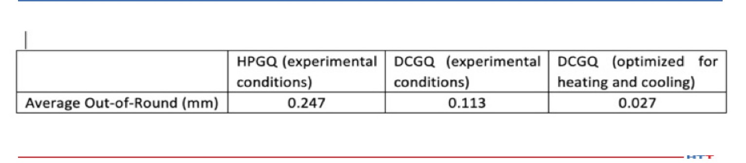
Table 2 compares the DCGQ simulation results in which the two processes executed on the experimental coupons were compared to an optimized process, including controlled heating and cooling schedules designed for this coupon. The optimized schedule predicts an order of magnitude reduction in out-of-round distortion. Comparison of the measurements from the HPGQ and DCGQ experiments in Table 1 to the model predictions in Table 2 shows that the model predictions agree closely with the experimental results.

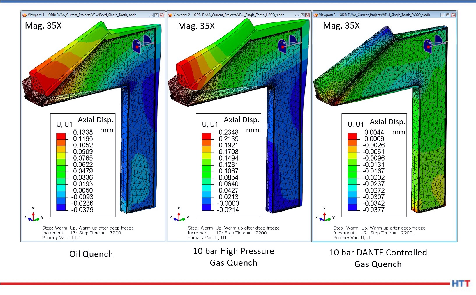
Simulating the application of the DCGQ process to a gear geometry, the predicted warpage of a bevel gear was examined. The simulation looked at the differences between an oil quench, 10 bar HPGQ, and a 10 bar DCGQ process. From Figure 5, it is clear that the HPGQ process is predicted to produce the most distortion. Even though the 10 bar gas quench has a slower cooling rate than the oil quench, less distortion is not guaranteed since a slower rate does not guarantee a more uniform phase transformation.[3] In this case, both heating and cooling were controlled for the DCGQ simulation.

Figure 5. Comparison of oil quench, HPGQ, and DCGQ processes for a bevel gear

In summary, a prototype gas quenching unit has been constructed with the ability to accurately control the temperature of the quench gas entering the quench chamber. Experimental results have shown that mechanical properties and microstructure are equivalent between the DCGQ process and a 2-bar HPGQ process for Ferrium C64. Thick disks with eccentric bores were machined and then heat treated using DCGQ and HPGQ. It was shown that the DCGQ process reduced distortion in these disks by 50%. Simulation using DANTE then showed that the distortion could be reduced further if controlled heating and cooling are used. Finally, a comparison was made between an oil quench, HPGQ, and DCGQ processes for a bevel gear. This comparison showed that the HPGQ process was predicted to cause the most distortion. HTT

References

[1] Prabhudev, K.H., Handbook of Heat Treatment of Steels, Tata McGraw-Hill Publishing, 1988, p.111-114

[2] Sinha, Anil Kumar, ASM Handbook, Vol. 4: Heat Treating, ASM International, 1991, p.601-619

[3] Sims, Justin, Li Zhichao (Charlie), Ferguson B. Lynn, Causes of Distortion during High Pressure Gas Quenching Process of Steel Parts, Proceedings of the 30th ASM Heat Treating Society Conference, ASM International, 2019, p.228-236


About the Author: As an analyst of steel heat treat processes and an expert modeler of quench hardening processes, Justin Sims was the lead engineer for designing and building the DANTE Controlled Gas Quenching (DCGQ) prototype unit. This system was developed to minimize distortion of quenched parts made of high hardenability steels, while still achieving the required properties and performance.

For more information, contact Justin at DANTE Solutions


Process Innovation to Reduce Distortion During Gas Quenching Read More »

The Science of Combustion in an Era of Uncertainty

Carl Nicolia, President of PSNERGY, LLC (photo source: Carl Nicolia)

There was a time when the caveman’s torch was the top end of heat treating technology. We have since learned that all fire is not created equal.  Heat treat technology has evolved from fire to combustion and from combustion to efficient combustion.”

Join Carl Nicolia, president of PSNERGY, LLC, as he challenges industry leaders to evolve with viable and proven solutions to achieve combustion and furnace efficiency in this original Heat Treat Today article.

This article appears in the June edition of Heat Treat Today’s Automotive Heat Treating magazine.


As a technical professional, engineer, and self-proclaimed geek, in times of uncertainty I take comfort in going back to fundamentals. Going back to basic concepts defined by fundamental scientific principles of physics and heat transfer brings us to a point where we know what will happen, and this can give us all some comfort in these uncertain times. We can take comfort in knowing that when we combine the right mix of air and fuel with an ignition source, we will get fire! And as the caveman said, “Fire good!”

There was a time when the caveman’s torch was the top end of heat treating technology. We have since learned that all fire is not created equal. Heat treat technology has evolved from fire to combustion and from combustion to efficient combustion. We have learned how to optimize the delivery of energy produced by fire to achieve remarkable results. There is high-value technology available today (i.e. low cost with high impact) that can be quickly and easily implemented on existing furnaces, regardless of size or age.

Businesses are moving through some of the most challenging times in modern history. Even though a few months ago the economy was booming, we are now being pushed to respond in new and unique ways.  Many businesses, though, have existed for generations and have overcome other challenging market conditions. How did they survive? They evolved!

Darwin was right; “It is not the strongest of the species that survives, not the most intelligent that survives.  It is the one that is most adaptable to change. Intelligence is based on how EFFICIENT (my emphasis) a species became at doing the things they need to survive.”

Industries coming back online after extended down times and lost production days, are driving new customer demands for quality parts produced faster and cheaper. End customers are executing plans to ramp-up their plants to run at maximum efficiency. They are securing additional critical inventory and capacity from their supply chain. The productivity ante has been raised! Have your operations evolved to meet these demands?

Combustion efficiency and furnace efficiency are the heart of all gas-fired heat treating operations. Combustion and furnace efficiency can mean the difference between profit and loss, high quality and scrap, survival and extinction. Now more than ever, finding low-cost, easily-implemented technologies to increase efficiency is critical to your business’s evolution. Good news: Products and services enabled by revolutionary technology exist today and can improve the efficiency of your business. Because the technology is revolutionary, the implementation is simple.

Case Study

To understand the impact of this type of innovative technology, let’s look at an example from a contract heat treating company with a 9’ IQ box furnace. This batch annealing furnace is heated by four 5” ID x 65” U-tubes with bayonet recuperators. The company installed the latest technology of radiant tube inserts (RTI) into the exhaust legs of the radiant tubes. Once the RTI’s were installed, the combustion system was tuned, utilizing the latest sensing technology.  The results are impressive:

  • Recovery cycle time reduced by 25%
  • Total gas consumption per load reduced by 5%
  • Furnace output increased by 10%

Total time to implement this solution was one day. Total cost to implement this solution was less than $10,000. Payback on this installation was less than three months!

Combustion Efficiency

Combustion efficiency is getting the most energy out of the gas purchased and ensuring you continue getting that same level of performance. Most talk about the importance of proper tuning, yet how many recognize the likelihood they are not running optimally today and can quantify the impact? A furnace running just two points out of tune at 5% excess oxygen is delivering 8% less energy to the system. Jump that to 7% excess oxygen and you are throwing away over 20% of the energy. Keeping the combustion system in tune is critical (Figure 1).

Figure 1: Impact of proper combustion tuning. (photo source: Carl Nicolia)

Just like the caveman, gone are the days of running through the burners with a handheld meter once a year, making adjustments based on a single point in time. There are combustion engineering service teams utilizing the latest technology to achieve higher levels of system performance. It is no longer acceptable to take a burner view of combustion: It must be at the combustion system level. If your service team is still working with single handheld meters, it is time to evolve. At a minimum, service teams today should be equipped with the latest sensing technology that allows them to view combustion in entire zones, if not entire furnaces, record data over the range of operation, and store this data for trending and preventive maintenance.

Once the combustion system is tuned, it is necessary to ensure the system stays tuned. Technology that monitors combustion across the entire furnace multiple times per day is available. Utilizing the latest sensing equipment, along with leading edge controls and IIOT technology, these systems seamlessly collect, analyze, and store combustion data and provide simple actionable alerts that keep your combustion system operating at maximum efficiency. Utilizing this type of technology allows you to stay ahead of combustion efficiency in real time and prevent your operation from throwing away profits.

Furnace Efficiency

Getting and keeping maximum combustion efficiency is certainly the first step in your evolution; however, the only thing you get paid for is getting that energy to product. How well the energy provided through efficient combustion is transmitted to the product being processed is called furnace efficiency. Again, there is low-cost, high-value technology available to increase furnace efficiency.

Waste heat recovery technology continues to evolve. Recuperators have been a great first step that many in the industry have incorporated into their systems, but there is more that can be done.

Ceramic inserts are waste heat recovery devices that work alone, or in conjunction with recuperators, balancing the energy delivered across the entire length of the radiant tube, significantly improving furnace efficiency as well as increasing radiant tube life. Recent technological advancements in ceramic insert design and material have increased the effectiveness of ceramic inserts. Additionally, alternative radiant tube designs, such as bubble tubes and textured tubes, help deliver more energy to the product.

Don't let your radiant tube furnace be the caveman of your operations. Take comfort in understanding that all fire is not created equal, and many combustion technology advancements are based in fundamental scientific principles. Get more information on these low-cost and easily implemented technologies available to the heat treating industry today. Recognize that utilizing these revolutionary technologies is the key to evolving your business to measurably higher levels of responsiveness and performance and will allow your business to thrive in this environment.

Will you evolve?


About the Author: Carl Nicolia is president of PSNERGY, LLC, which provides modern solutions to combustion problems, improving equipment life, enhancing productivity, and reducing emissions through smart application of proprietary products, services, and technology.

For more information, contact Carl at cnicolia@psnergy.com or 814.504.2326.

(photo source: Charles Ronodeau from Pixabay.com)

The Science of Combustion in an Era of Uncertainty Read More »

Heat Treat Learning: Principles of Heat Treatment

Neil Hardy, Metallurgical Specialist and Creator of MetallurgyData (photo source: Neil Hardy)

In this Heat Treat Learning special, metallurgical technician and specialist Neil Hardy at MetallurgyData shares about the background of developing his educational video endeavors for people in the heat treat industry. This information was taken from an interview with Heat Treat Today and has been curated for educational purposes. This video is a part of Heat Treat TV.

Heat Treat Learning is a series of curated pieces for Heat Treat Today's audience, intended to aid end-users in their continual professional development. If you have a piece that you believe might be helpful on this platform, email any of our editors with your information and we will be in touch. Our contact info is Bethany Funk - bethany@heattreattoday.com, Karen Ganzter - karen@heattreattoday.com, or editors at editor@heattreattoday.com.


Back to the Basics: Heat Treatment Types, Processes and Structures

This "back to the basics" video demonstrates the different outcomes of heat treatment types, processes, and structures. In it, the video offers clear parameters for how and why different heat treating methods matter for particular metals and for intended outcomes. It is provided by MetallurgyData, a global informational training platform based on providing metallurgical principles to aid understanding for application.

MetallurgyData on YouTube

MetallurgicalData produces educational content, as well as topics of interest. "I am currently producing a video that follows the process of me replicating my late father’s wedding ring. He died at the age that I am now so this project has quite a lot of emotion associated with it for me," the creator of the platform, Neil Hardy, said, "This will be video-graphic ad show the process of making the ring while the other will be based around the science of each stage of the process including, melting, casting and forging."


About MetallurgyData and Neil Hardy

In 2005, Neil Hardy, a Metallurgical Specialist, gained his bachelor’s degree in material engineering while working in lab and testing settings. Continuing to work at an international steel company before finally arriving in 2010 at a UK forge, Neil's experience has been continuously focused on the cutting edge.

Recently in his career, Neil began something less bent on new technology but still cutting edge. A self-funded project, MetallurgyData,  started about five years ago. "It evolved," Neil said, "from two ideas; the first was to produce an online property prediction calculator and the second was around providing online training courses."

While Neil did not pursue the property production calculator idea, the online training courses were a hit. They have evolved into the videos that are currently available on YouTube. "I think there is a gap in the market for producing online training courses in metallurgy and I initially thought to pursue this with a 'fundamentals in metallurgy' course."

[blockquote align="left"]I think there is a gap in the market for producing online training courses in metallurgy and I initially thought to pursue this with a "fundamentals in metallurgy" course.[/blockquote]

Neil is looking to expand his YouTube platform to provide additional content, and is eager to develop more videos for companies in order to facilitate more informational content for his growing audience.

For more information, email Neil Hardy at metallurgydata@gmail.com, message him via MetallurgyData on LinkedIn, or leave comments on his YouTube Videos.

Heat Treat Learning: Principles of Heat Treatment Read More »

International Aerospace Manufacturer Buys 2 Vacuum Furnaces

An international aerospace manufacturer orders two furnaces for its factories in the USA and Singapore. While both are single-chamber vacuum furnaces, they will serve different functions. One will be used for the heat treatment of exotic electrical steels, and the second will be used for annealing parts produced by 3D printing technology.

The furnace purchased for the heat treatment of exotic electrical steels has diffusion vacuum levels and a horizontal chamber. The chamber has the workload size of 24” x 24” x 36” and a 1300 lb. hearth capacity. Additionally, each furnace has a single-chamber, high pressure gas quench heat treat system adaptable to a wide variety of thermal processing applications including annealing, brazing, hardening, LPC and LPN, normalizing, solution heat treating, sintering and tempering.

Two SECO?WARWICK Vector Furnaces (photo source: SECO/WARWICK)

Each of the furnaces were bought from SECO/WARWICK Vector furnaces lines. This is the manufacturer's first purchase for a US installation from this supplier. The Vector furnaces lines are used in multiple applications within the aerospace sector, including heat treating turbine blades and landing gear, as well as in the aerospace aftermarket to maintain fleets of aircraft.

Maciej Korecki, Vice President of Vacuum Business Segment, SECO/WARWICK (photo source: SECO/WARWICK.com)

“SECO/WARWICK Group," commented Maciej Korecki, Vice President of Vacuum Business Segment at SECO/WARWICK, "has delivered hundreds of Vector heat treat systems worldwide, many of which are in steady use supporting the aircraft industry. We offer Vector with either a horizontal or vertical chamber depending on part configuration and the process needs of the customer, and we support each customer all over the world with a dedicated team of aftermarket professionals to keep them running at peak efficiency.”

Vector 3D builds upon the single-chamber vacuum furnace technology to combine the advantages of gas quenching capabilities with the growing requirements of the additive manufacturing market. The result allows customers to perform processes such as sintering, debinding, stress-relieving, aging or solution heat treatment, which are essential for the metal 3D printing sector. It has numerous applications in such industries as aerospace, automotive, medical and energy.


(photo source: NASA on unsplash.com)

International Aerospace Manufacturer Buys 2 Vacuum Furnaces Read More »

Helium to Nitrogen: A Cost-Efficient Change in Heat Treat Hardening

Solar Atmospheres of Western PA is currently installing a new rapid quenching vacuum furnace that will ultimately eliminate the need for costly helium while increasing production throughput. In helium's place, the new furnace will use nitrogen only in the hardening process.

Solar Manufacturing Rapid Quench Furnace for Solar Atmospheres of Western PA  (photo source: Solar Atmospheres)

The new 48” x 48” x 96” deep 10 bar vacuum furnace is produced by Solar Manufacturing. The important difference in this furnace from its older model is the cooling design, which is equipped with a 600 HP blower designed motor. This will allow the new furnace to outperform its older model by processing larger and heavier workloads with the use of nitrogen only.

Bob Hill, President, Solar Atmospheres of Western PA

“The difference in operating costs is a no brainer,” states president of Solar Atmospheres, Bob Hill. “To marginally harden one 2000-pound high-speed tool steel roll die in our older 2 bar vacuum furnace, the use of light helium gas was a necessity. The prohibitive cost of a two atmosphere helium backfill was $1,065. Our new furnace will enable us to fully harden three 2000-pound roll dies at once using the more cost-effective process gas of nitrogen. In contrast the cost of a 10 atmosphere backfill of nitrogen will be only $89.” Hill predicts that with these increased efficiencies and savings, his normal ROI on a new piece of equipment will be significantly advanced.

Once operational, Hill will author a technical paper with the actual cooling data derived from these similarly sized vacuum furnaces.


(photo source: NASA at unsplash.com)

Helium to Nitrogen: A Cost-Efficient Change in Heat Treat Hardening Read More »

Predicting the Effects of Composition Variation for Heat Treatment of Aerospace Alloys

In the following original content from Heat Treat Today, Thermo-Calc Software's Adam Hope, PhD, materials scientist, and Paul Mason,  president, delve into how modeling and simulation tools can help heat treaters make well-informed decisions.

This article first appeared in the latest edition (March 2020) of Heat Treat Today’s Aerospace Heat Treating magazine.


Consistency in material properties and performance is critical to the aerospace industry, and small variations in material chemistry or process windows can have a large impact on the final parts performance. The ability to predict and adjust for these variations can reduce scrap and part re-work. Metallurgists and process engineers responsible for heat treatments must adapt their process when input variables change, such as material chemistry. They are routinely faced with questions such as:

Paul Mason
President
Thermo-Calc Software

*How will heat to heat variations affect the final part performance?

*What heat treatment should be given to a part that has been built via a novel approach such as additive manufacturing?

*How should one optimize a heat treatment schedule for a new alloy?

*When the data required to make these decisions does not exist, what are the options?

Experiments can generate this data, but this is costly and time-consuming. Handbooks might have data for known alloys, but this is often only for the nominal composition and may not be suitable for material processed under a novel route. Modeling and simulation tools can help fill this knowledge gap and help inform better decisions.


Integrated Computational Materials Engineering and CALPHAD

Adam Hope, PhD
Materials Scientist
Thermo-Calc Software

The publication by the National Academies in 2008 on Integrated Computational Materials Engineering (ICME)[1] outlined an approach to designing products, the materials they are comprised of, and their associated materials processing methods, by linking materials models at multiple length scales. The report highlighted the need for a better understanding of how processes produce material structures, how those structures give rise to material properties, and how to select materials for a given application, describing the need for using multiscale materials modeling to capture the process, structures, properties, and performance of a material.

Computational thermodynamics, and specifically CALPHAD (CALculation of PHase Diagrams)[2], enables the prediction of the thermodynamic properties and phase stability of an alloy under stable and metastable conditions. The CALPHAD approach captures the underlying composition and temperature dependence of properties and can also be extended to model atomic mobilities and diffusivities in a similar way. By combining thermodynamic and mobility data, kinetic reactions during solidification and subsequent heat treatment processes can be simulated. Computational thermodynamics and CALPHAD- based tools are an important component of an ICME framework because, through the use of such simulations, it is possible to vary alloy compositions and predict optimal solidification processes and solution heat treatment temperature ranges without performing many time-consuming and costly experiments.

Predicting Heat Treatments for Additively Manufactured Parts

Many additive manufacturing processes subject the material to rapid solidification with multiple subsequent reheat cycles. The effect of these thermal cycles on material properties is not always known and typically does not result in the properties that a similar cast or wrought metal would have. Additionally, many additively manufactured parts are built using conventional alloys which have been engineered for cast or wrought processes. In some cases these alloys are not suitable for additive processing, and problems such as deleterious phases forming during a post-build, stress-relief heat treatment, designed for conventionally treated alloys, may result.

Additive processes are typically associated with rapid cooling rates and large thermal gradients. This can give rise to the following:

  1. High levels of residual stress in the final part
  2. Microsegregation during solidification of each layer, which leads to local inhomogeneities in alloy composition

In the case of additive manufacturing, these separate heat treatments are often combined, and stress relief heat treatments designed for cast or wrought material may not be suitable for additively processed materials for two reasons:

  1. The chemical inhomogeneities arising from rapid cooling can influence precipitation behavior, and some deleterious precipitates may precipitate more quickly than expected.
  2. The multiple heating cycles of subsequent layers may have already started some precipitation reactions, making stress relief more difficult without first homogenizing these precipitates.

Zhang et al.[3] have studied laser powder bed builds of Alloy 625 and found that after applying an industry recommended stress relief heat treatment, delta phase can precipitate in the segregated regions much faster than in the wrought material. The formation of delta phase is extremely detrimental to material properties. They attributed this to increased Nb and Mo concentrations found in the interdendritic regions in the as-built microstructure.

To understand this further, the authors first simulated the extent of this segregation using the Scheil-Gulliver model for solidification in Thermo-Calc[4] in conjunction with the diffusion module, DICTRA[4]. They then used the Precipitation module, TC-PRISMA to predict the precipitation kinetics of the deleterious delta phase for nominal feedstock compositions, as well as the compositions measured at dendrite boundaries. Both simulations, shown in Figures 1a and 1b, predict that a stable MC carbide forms, followed by some gamma double prime. Delta phase then forms at the expense of the gamma double prime. However the gamma double prime and delta phase both precipitate much more quickly in the segregated interdendritic region, due to the increased Nb and Mo. Delta phase is predicted to start forming around 1 hour, compared with 10 hours for the wrought material.

Figure 1. TC-PRISMA Precipitation simulations using nominal IN625 powder compositions (top) and segregated compositions (bottom) measured at the dendrite boundaries. Recalculated based on Reference 3.

While these calculations give insight to the reason why the conventional stress-relief heat treatment is not suitable, additional simulations can be made to identify a suitable temperature and time to both homogenize and stress-relieve the part, while avoiding deleterious phases. The authors of the study determined a post-build homogenization treatment was required to avoid deleterious delta phase precipitation.

Gas Carburizing Highly-Alloyed Steels

Highly-alloyed stainless steels can be gas carburized to increase the surface hardness, as well as improve the overall mechanical characteristics of the surface. However, an increase in chromium-rich carbides such as M23C6 or M7C3 can result in the decrease of chromium in the solid solution which leads to a reduction in corrosion resistance. Balancing these properties can be time consuming through trial and error experimentation, but CALPHAD-based tools can be used to identify suitable alloy compositions and heat treat windows, which are optimal for the application needs prior to testing in the laboratory.

Turpin et al. 5 made such a study, combining both experimental work and theoretical simulations to investigate carbon diffusion and phase transformations during gas carburization of high alloyed martensitic stainless steels. First, using thermodynamic calculations performed with Thermo-Calc 4 they determined the optimal balance between the carbide formation and chromium content of the alloy for corrosion resistance. They concluded:

  1. At 1750°F (955°C), which corresponds to the austenitization temperature of their alloy, M23C6 and then M7C3 will be the first carbides to precipitate in the austenite phase as the amount of carbon content in the alloy is increased.
  2. If the amount of carbon exceeds 3.8 wt% then M3C carbides are predicted to be stable. M3C carbides have a structure similar to cementite and preferentially precipitate at the grain boundaries which weaken the microstructure. Therefore, to avoid these phases, the overall content of carbon in the steel must be below this amount at the end of the carburizing process.
  3. Above 1.7 wt% C, the mole fraction (an indicator of the volume fraction) of M7C3 carbides exceeds 20%, and the chromium content of the alloy associated with these carbides is 65 wt%. Therefore, there is a correspondingly strong depletion of chromium from the matrix.
  4. To balance the desire for adding carbon into the matrix phase to obtain hardness with depleting the matrix of carbon, it was determined that the optimal amount of carbon in the matrix phase should not exceed 1 wt%. Thus, the thermodynamic calculations were used to establish a limit, without yet any consideration of the kinetics or time.

The second stage of the study then considered the diffusional reactions in the multi-component system during i) the carbon enrichment step and ii) the diffusion step of the gas carburizing process, and to determine how the composition and the amount of each phase vary with time and distance from the gas/solid interface and the carbon profile of the alloy as a function of time and distance. These calculations were made using the diffusion simulation software, DICTRA 4.

Consider the carbon enrichment step first. In DICTRA, several boundary conditions can be used for such a simulation, and in this work the carbon flux was determined experimentally using thermogravimetric measurements. During the diffusion step, the N2-CH4 mixture is replaced with pure N2, and the carbon flux at the surface of the samples is zero. To simulate this step using DICTRA, a zero carbon flux was applied as the boundary condition for two hours.

Figure 2 shows a simulated carbon profile for Fe-13Cr-5Co-3Ni-2Mo-0.07C, which is found to be in good agreement with the experimental values reported by Turpin et al. The authors concluded from this study that the carbon profile can be calculated and followed at any time if the boundary condition evolution at the gas-solid interface is known during the carburizing treatment.

Figure 2. DICTRA carbon diffusion profiles for Fe-13Cr-5Co-3Ni-2Mo-0.07C. Recalculated based on Reference 5.

Predicting β-transus Temperatures in Ti-Alloys

Many Titanium alloys respond well to heat treatments, through which the microstructure can be manipulated to optimize properties for a particular application. For example, some microstructures are better for high temperature creep, and some are better for fatigue strength. This is primarily achieved by controlling the nature and amount of α and β phases in the microstructure.

At high temperatures, titanium alloys are primarily β phase. At the β-transus temperature, the α phase becomes stable and can start to form. The β-transus temperature can change as a function of alloy chemistry. Knowing the β-transus temperature is critical to determining the nature and amount of α phase that will form during a heat treatment or thermal cycle.

Many alloying elements in Ti alloys have a strong effect on β-transus temperature. Knowing the actual β-transus for a specific chemistry is critical to determining suitable heat treating windows to obtain a specific set of material properties. However, even within a particular alloy specification, there can still be small compositional variations that have a significant effect on the β-transus. Thermo-Calc [4] can be used to calculate this if the exact chemistry is known, or to determine the potential distribution of β-transus temperatures for a given chemistry range.

Table 1 -- Composition specification for major elements in Ti-6-2-4-2 Alloy

Table 1 shows the composition ranges for the major elements in Ti6-2-4-2Si (AMS 4919). Figure 3 shows the calculated distribution of β-transus temperatures in the composition specification of Ti6-2-4-2. Over 40 degrees variation is possible for compositions that lie within the specification and the calculations show good agreement with the experimentally measured values of 995°C ± 15°C (1823°F ± 27°F).[6]

Figure 3. Variation in Beta transus temperature for 1000 possible compositions within Ti-6-2-4-2 specification


Summary

In the 100th Column of the Heat Treat Doctor [7], Dan Herring, stated that heat treating can best be defined as “the controlled application of time, temperature and atmosphere to produce a predictable change in the internal structure (i.e. the microstructure) of a material.” However, variability arising from composition differences in materials can sometimes be challenging for heat treaters. The examples shown here have illustrated how modeling and simulation tools such as those based on the CALPHAD approach can be used to predict variability arising due to material composition. HTT

References

[1] National Research Council. 2008. “Integrated Computational Materials Engineering: A Transformational Discipline for Improved Competitiveness and National Security.” Washington, DC: The National Academies Press.

[2] Kaufman, L and Bernstein, H. Computer Calculation of Phase Diagram. New York: Academic Press Inc, 1970.

[3] Zhang, Fan, et al. “Effect of heat treatment on the microstructural evolution of a nickel-based superalloy additive-manufactured by laser powder bed fusion.” Acta Materialia 152 (2018) pp 200-214.

[4] Andersson, J O, et al. “Thermo-Calc and DICTRA, Computational tools for materials science.” Elsevier, CALPHAD, Vol. 26, (2002) pp. 273-312.

[5] Turpin, T, et al. “Carbon diffusion and phase transformations during gas carburizing of high-alloyed stainless steels: experimental study and theoretical modeling.” Met. Trans. A, Vol. 36A, (2005) pp 2751-2760.

[6] TIMET datasheet for TIMETAL® 6-2-4-2, TMC-0157 (2000).

[7] Herring, D “What is Heat Treating and Why Do We Do It?” Industrial Heating Magazine BNP Media (2011).


About the authors: Paul Mason is the president and Adam Hope, PhD is a materials scientist for Thermo-Calc Software, whose products assist academia, government, and industry to make calculations which predict or assist in the understanding of complex multicomponent alloys and non-metallic systems, as well as processes of industrial and scientific relevance.

For more information, contact Paul or Adam at info@thermocalc.com or (724) 731 0074


(Photo source: dayamay from pixabay.com)

Predicting the Effects of Composition Variation for Heat Treatment of Aerospace Alloys Read More »

Kuczma to Acquire Single-Chamber Vacuum Furnace

SECO/Warwick Vector Furnace (photo source: SECO/Warwick)

A family-run, commercial heat treating plant in Rzeszów, Poland, Kuczma Hardening Plant, will expand its heat treating capabilities with a new single-chamber vacuum furnace. A particular addition to this furnace is the directional cooling, which will allow the plant to perform quenching from both the sides and the top and bottom in order to precisely adjust the gas cooling system to the batch configuration.

The Vector® vacuum furnace from SECO/WARWICK is equipped with 1.5 bar gas quenching pressure. It will increase the capacity of the Kuczma Hardening Plant and will enable the plant to process parts with dimensions up to 600x600x900 mm. This furnace model specializes in heat treating many types of materials and metal alloys; additionally, its functionality includes gas hardening and tempering, annealing, brazing and degassing.

Kuczma Steel Heat Treat facility (photo source: http://hartownia-kuczma.ugu.pl/?page_id=35)

"Kuczma Hardening Plant," said Jerzy Kuczma, Kuczma Hardening Plant owner, "specializes mostly in vacuum quenching in gas, oil and gas nitriding of injection mould components and dies... On one hand, the SECO/WARWICK furnace will enable us to process larger components and increase our output for smaller ones on the other it will enable directional cooling sideways or top/bottom."

The hardening plant also performs carburizing, quenching, and tempering under protective endothermic atmosphere as well as clean stress relieving under nitrogen atmosphere.


(photo source: http://hartownia-kuczma.ugu.pl/?page_id=35)

Kuczma to Acquire Single-Chamber Vacuum Furnace Read More »

This Week in Heat Treat Social Media


Welcome to Heat Treat Today's This Week in Heat Treat Social Media. As you know, there is so much content available on the web that it's next to impossible to sift through all of the articles and posts that flood our inboxes and notifications on a daily basis. So, Heat Treat Today is here to bring you the latest in compelling, inspiring, and entertaining heat treat news from the different social media venues that you've just got to see and read!

If you have content that everyone has to see, please send the link to editor@heattreattoday.com.


1. What do Quality Aerospace Bolts Look Like?

"Quality aerospace bolts are more rigorously tested, more carefully manufactured, and more carefully studied than almost any other component on an aircraft. The reason?" Read more here, and check out the video to see high-impact landing that is required of fighter jets. See 5:10-8:06 for a forced landing on a stool when the pilot's nose gear failed.


2. Hot Heat Treat Technologies

Walk through this CGI Animation of Vacuum Brazing process to see the breakdown of the heat treating process without getting burnt.


3. Advancing Technologies

Check out TWO uses of cutting edge digital systems when applied to heat treat, and industry related processes. See below for the videos.


Digital Transformation of Thermal Processes

.

Tracking All Processes with Digital

SMS Digital: BIG RIVER STEEL - THE FIRST LEARNING STEEL PLANT


4. The Podcast and Reading Corner

Ever wanted to have access to resources for on the job training? Read or listen to the sources below to learn a new technique, tip, or other aspect of the industry.

.

A NEW Metal? Check out what carburizing and hardening can do.

"...carburized A-21 exhibited superior corrosion resistance in salt fog testing versus the other stainless steels. It also maintained good core mechanical properties of..."

.

The "How" Behind Nitrex's Rebranding

.

Finding a Balance: Read Ipsen's Blog, The Herald, on additive manufacturing  and the thermal processing industry.

[blocktext align="center"]"Additive manufacturing is a disruptive technology with the potential to lower cost, increase speed and create parts once thought to be too complex and intricate to manufacture by conventional methods."[/blocktext]

"Balancing the Speed and Technology of Additive Manufacturing with the Mature and Methodical Thermal Processing Industry" (photo source: IpsenHarold.com)


5. Metal Music

Finally, here is some not-so-heavy metal music to start your weekend. Big thanks to Rosanne Brunello of Mountain Rep for the find! Have a great weekend, folks.

This Week in Heat Treat Social Media Read More »

Mexican Auto Supplier Upgrades 4 Zone Brazing Furnace

An automotive parts supplier in Mexico will receive a rebuilt 24 inch, four zone continuous mesh belt brazing furnace.

Continuous Mesh Belt Brazing Furnace (photo source: Gasbarre Thermal Processing Systems)

The rebuild included a new 330 stainless steel muffle, new silicon carbide heating elements, new cooling sections, and new furnace controls to meet CQI-9 requirements. The CQI-9 controls package includes data acquisition, preventative maintenance alerts, remote connectivity, furnace parameter trending, and temperature deviation alarms.

The partner chosen for this rebuild, Gasbarre Thermal Processing Systems, designs, manufactures, and services a full line of industrial thermal processing equipment, offering batch and continuous thermal processing equipment for both atmosphere and vacuum applications as well as a full line of alloy fabrications, replacement parts and auxiliary equipment.

(photo source: Peter Broomfield at unsplash.com)

Mexican Auto Supplier Upgrades 4 Zone Brazing Furnace Read More »

Magnetic Shields Ltd Orders Heat Treating Vacuum Furnace

Magnetic Shields Ltd. of Kent, England, a producer of medical industry equipment, has ordered a new vacuum furnace for their facility, set to be one of the largest horizontal vacuum furnaces in the UK.

Solar HFL-7496-EQ Vacuum Furnace (photo source: Solar Manufacturing)

The new HFL-7496-EQ vacuum furnace, being built with a SolarVac® Polaris control system, will be designed to accommodate loads up to 48” wide x 48” high x 96” deep, (1220 x 1220 x 2440mm) with a maximum weight of 5,000 lbs (2270 kgs). Operating at a vacuum level of 10-5 Torr, the furnace will be able to reach temperatures up to 2400°F (1315°C). It will feature a partial pressure hydrogen gas process and an external quench system designed for negative pressure quenching.

Magnetic Shields Ltd. Director Colin Woolger (see image below) says, “Magnetic Shields is delighted to order our second vacuum furnace from Solar Manufacturing. The new furnace will enable us to more than double the maximum size of shields we can now produce in one piece and also increase the general heat treatment capacity for our growing company... We look forward to the new furnace arriving later this year.”

Magnetic Shields Ltd. of Kent, England began its relationship with their seller, Solar Manufacturing of Sellersville, PA, in 2016 when Magnetic Shields Ltd. bought a vacuum furnace from the heat treating furnaces provider.

Rick Jones, VP of International Sales at Solar Manufacturing also adds, “Solar Manufacturing is very pleased to be selected as the supplier to further support Magnetic Shields in leading the production of equipment for the medical industry and other high technology applications, specifically, high performance large magnetic shields and low field shielded rooms.”


Read more about Magnetic Shields Ltd.'s first vacuum furnace from Solar Manufacturing in this press release.

To read more about the 2017 Magnetic Shields Ltd.'s reception of their first Solar Vacuum Furnace, click here. Pictured on the left is Colin Woolger, Chairman of the company, Suzie McKay, Rob Latter. (Photo source: magnetshields.co.uk)


Magnetic Shields Ltd Orders Heat Treating Vacuum Furnace Read More »