Brinell Hardness Testing 101
What are the most desirable attributes of a Brinell hardness tester? Does it belong in your heat treat department? Read this equipment overview to decide.
Read the English translation of this article in the version below or read the Spanish translation when you click the flag to the right. Both the Spanish and the English versions were originally published in Heat Treat Today's August 2023 Automotive Heat Treat print edition.

Managing Director
Foundrax Engineering Products Ltd
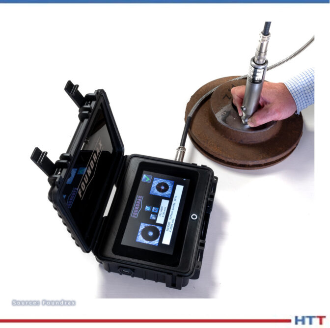
Source: Foundrax
All heat treatment companies must test hardness; many with a Brinell tester. Existing since 1900, a review of this time-tested method is in order.

The Brinell test requires a tungsten carbide ball indenter to be forced vertically into the surface of the test material, placed on a rigid anvil. The diameter of the indentation made by the ball is then measured across both its x and y axes as a minimum, and the average of these measurements is taken as the working figure. The technician can then either feed that figure into an equation to determine the hardness or read from a “diameter-to-hardness” chart.
There are various forces and indenter diameters available for Brinell testing reflecting the very wide range of metals that need to be assessed, but most tests involve a 10 mm ball under a 3,000 kg load. In large, floor standing machines, the indenter is usually motor-driven, but some machines use levers and weights, while others are hydraulic or pneumatic. The Brinell test remains the default method for hardness measurement in many heat treatment facilities, for three primary reasons.
1. Surface Preparation
Preparing the surface of a sample for Brinell testing takes just a few seconds with a grinder. Provided the sample is sitting steadily on the anvil and the top face of the sample is perpendicular to the direction of force of the indenter — as mandated by the standards — the surface does not need to be particularly smooth.
2. Surface Contamination
Minute surface contaminants under a Brinell indenter are unlikely to cause a “mis-test.” By comparison, during Rockwell testing, the most widely used method across all industries, a tiny diamond indenter penetrates the surface by less than one hundredth of an inch, and any contaminants or surface abnormalities (including parallelism) that could impede or assist the progress of the indenter are a problem, which means that Rockwell samples must be carefully prepared before testing.
3. Portable
Perhaps most significant, rugged, hand-held portable Brinell testers with hydraulic test heads enable large, heavy, and awkwardly shaped components of rough surface finish to be tested in situ. This feature is of such utility in industry that the international standards authorities give a dispensation — a special designation — to portable machines, although their performance cannot be directly verified like their floor-standing cousins.
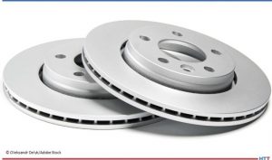
With forces ranging from 3000 kg down to 1 kg and indenter balls as small as 1 mm, Brinell testing can be used on a vast range of metal, but forges, foundries, heat treatment plants, quality control areas, and laboratories are the places one would most likely find a test machine working at 10 mm/3000 kg. It was mentioned earlier that the surface of test samples doesn’t need to be particularly smooth, in fact roughly- ground surfaces on materials with a coarse grain structure can be measured quite safely because the diameter of the indentation is so large relative to any irregularities on the surface.
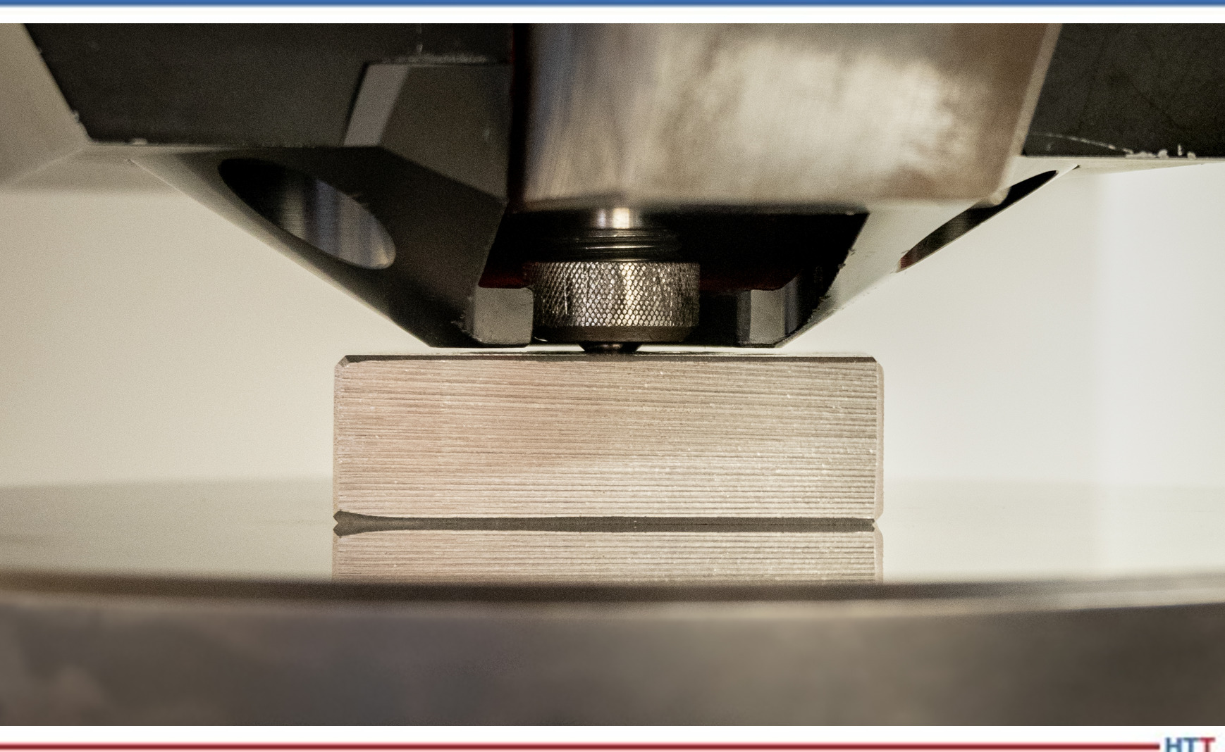
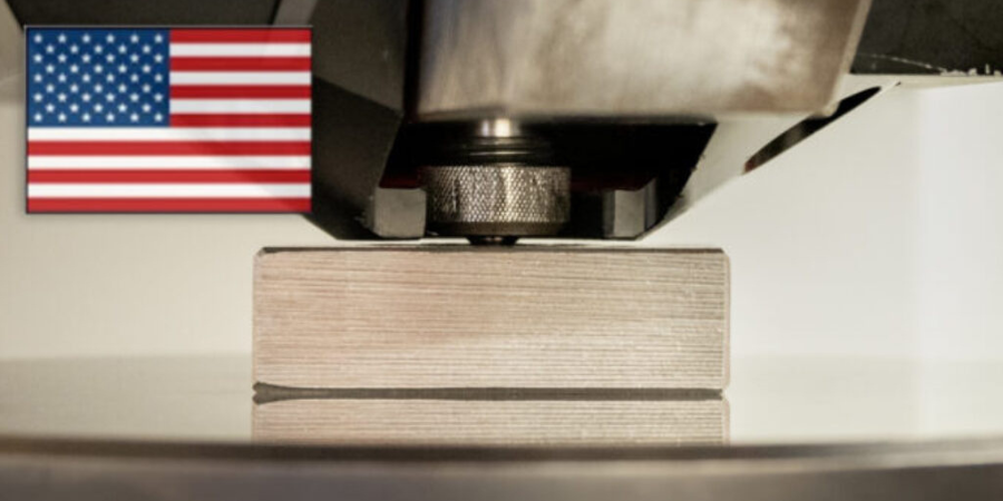
In Figure 2, a calibration-grade Brinell tester drives the tungsten carbide ball into the test sample. The ball is being held in position to stabilize plastic deformation. ASTM E-10 and ISO 6506 — the authoritative documents for Brinell testing — lay out standards in detail, but the practical procedure for workshop technicians is very straightforward; training should not take longer than an hour. When testing forgings, billets, and other samples, one indentation should suffice but in certain critical applications more than one indentation may be used for assurance.
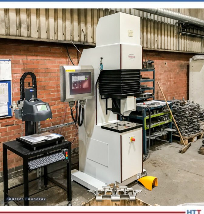
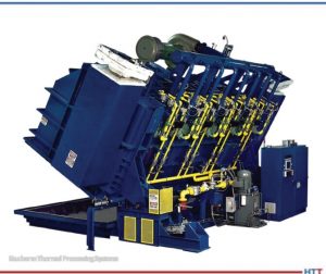
The question of whether to test every sample in a batch will depend on how inconsistent those samples might be; it has nothing to do with any issues with Brinell testing itself. In certain industries, every single product is tested because the risk of failure is too high. A good example of this is the production of links for the tracks used on tanks and other armored vehicles. Every link in every tank track in use by the British Army has been Brinell tested on a high-speed, fully automatic machine that features a powerful integral clamp to keep the component rigid during the test. You can view the machine in Figure 1 on page 44. Subject to reasonable care, a heavy-duty Brinell tester will perform many hundreds of thousands of tests. The machine in Figure 1 has performed several million.
Tests take approximately fifteen seconds. The indenter must be driven uniformly into the material with no possibility of either a rebound or a speed that would “punch” the indenter into the material. Also, the metal must be loaded for a sufficient length of time to ensure the indentation is properly (plasticly) deformed, that is, the risk of an indentation shrinking very, very slightly after the indenter is withdrawn is kept to a minimum.
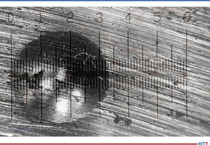
Measuring the indentation is more challenging. After carefully making the indentation and withdrawing the test sample from the “jaws” of the test machine, one must measure the indentation across at least two diameters. Given that Brinell indentations are at most 6 mm across and that 0.2 mm difference in diameter might equal 20 hardness points, getting the measurement right is critical — and tricky. Most technicians will use an illuminated microscope to do this, but even then it can be a challenge. Consider Figure 3 on the next page.
Making an indentation leaves a “ridge” at the indentation perimeter because metal is not just pushed downwards, but also sideways. This ridge can obscure where the real indentation begins, and three different technicians can easily make three different estimates of where that is. And this variation in operators’ interpretation of results is why, for over 80 years, the Brinell test was seen as a little “rough and ready,” for the workshop machinist, perhaps, but probably not for the laboratory scientist.
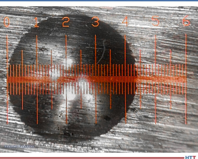
Manual measurement microscopes have improved over the years, and a relatively “clean edged” indentation with a crisply illuminated graticule can be less challenging for the experienced technician to make an accurate measurement. Figure 4 is a less difficult scenario than the one above. Even so, how can we know if we have really judged the position of the edge precisely?
In 1982, the first automatic reader hit the markets. This was the culmination of years of research and used proprietary software that pushed the computers of the day to their limits. The equipment could make hundreds of measurements across the indentation and calculate the mean diameter in a split second. Not long afterwards, it was available as an integral part of a Brinell test machine. Word of this equipment soon reached critical users in the oil tool industry, and they mandated its use to their suppliers. Within 15 years, the use of this technology was widespread and the perception of the Brinell test’s accuracy had been transformed. The Brinell test, in a sense, had come of age. See Figure 5 for the latest version of that automatic microscope in action.
Finally, like any important measuring equipment, regular calibration and servicing is desirable, if not compulsory. Manufacturers typically stipulate a service schedule which must be considered alongside the calibration rules dictated by international agencies.
When considering options for hardness testing of heat treated samples, there are ultimately three test methods: Brinell, Rockwell, and Microhardness (Vickers or Knoop).
While Brinell testing isn’t suited to very small or very thin samples, it is relatively “immune” to small contaminants, the indenters are not expensive, and the width of the indentation means that testing of coarse grained and roughly finished surfaces is not problematic. With the development of reliable automatic indentation measurement, the one serious deficiency of the Brinell test was overcome, providing the assurance that was vital to critical components suppliers in all types of industries such as oil and gas, aerospace, defense, and transportation.
About the Author:
Alex Austin has been the managing director of Foundrax Engineering Products Ltd. since 2002. Foundrax has supplied Brinell hardness testing equipment since 1948 and is the only company in the world to truly specialize in this field. Alex sits on the ISE/101/05 Indentation Hardness Testing Committee at the British Standards Institution. He has been part of the British delegation to the International Standards Organization advising on the development of the standard ISO 6506 “Metallic materials – Brinell hardness test” and is the chairman and convenor for the current ISO revision of the standard.
For more information:
Contact www.foundrax.co/uk.
Find heat treating products and services when you search on Heat Treat Buyers Guide.com
Brinell Hardness Testing 101 Read More »


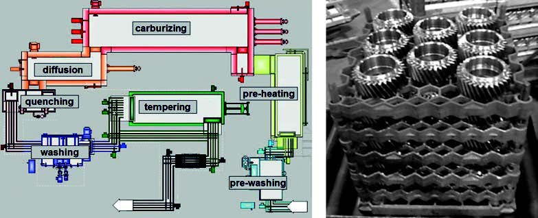 This paper reveals the investigation and conclusions of distortion potentials for case hardening processes. Mainly, the focus was on how the SyncroTherm® concept method compared to conventional case-hardening processes for gears and sliding sleeves.
 Problems in heat treating result in the loss of valuable time and money. Getting to the bottom of those problems also usually takes time and money to investigate what's happening and how to fix it. What is a heat treater to do?
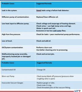
 Low pressure carburizing (LPC) furnaces play an important role in the automotive heat treating industry. During LPC, it is essential that processing temperature stays consistent and critical that the processing time frame is monitored.
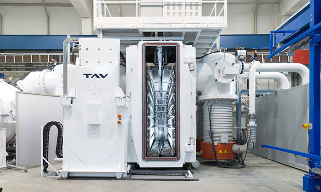 Time to brush up on a vacuum brazing furnace, but automotive industry style. Review the terms, parts, function, and more that are involved in a successful vacuum braze for automotive parts.
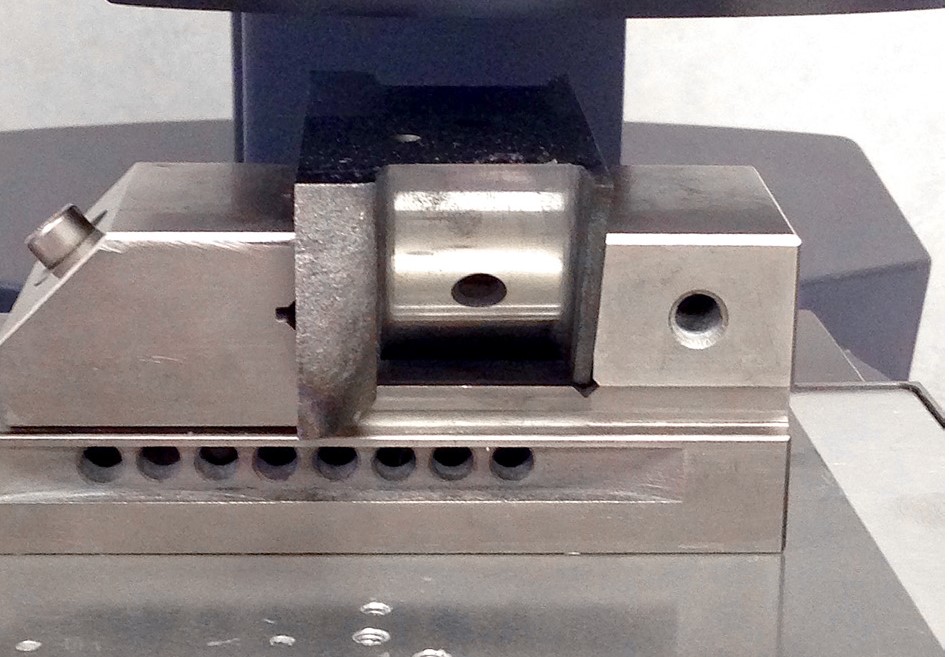 If you've ever heat treated automotive crank pins, you're probably familiar with at least one type of hardness test that case hardened crank pins are tested against. The big question is, which hardness testing method is better: automated or manual? This article compares these two methods to make and measure Vickers indentations.