Jim Roberts of U.S. Ignition engages readers in a Combustion Corner editorial about the hidden complexity of balancing furnace pressures —explaining how thermal expansion, gas velocity, and pressure fluctuation interact in modern burner systems, and how flue gas recirculation can push firing efficiency from 30% to 75% while cutting NOx emissions by more than half.
This editorial was first released in Heat Treat Today’sMarch 2026 Annual Aerospace Heat Treating print edition.
When I made the comment about the negative attitude in Part 1 of this series (Air & Atmosphere Heat Treating, February 2026), I was referring to the fact that most of these burner designs require a suction component (in this case, the eductor) to help pull the exhaust gases out over the heat exchanger portion of the burner. Also, if we just tried to pressurize the burners and force the exhaust gases out through the exchanger section, there would be a pressure buildup in the furnace. With that comes the destruction of door seals. Burner plates begin to leak, and when the doors open, the operators and furnace guys get greeted with a blast of 2000°F flue gas. I can honestly say, I have not, in all my years in this industry, met a furnace guy who likes a thermal haircut.
So, by balancing the pressures, we can save gas, reduce emissions, and probably even heat treat some products along the way.
A comment like, “just balancing the pressures,” seems like such an easy thing to accomplish. And, for all the experienced furnace guys out there, that is probably regarded as pretty simple stuff. But we have to give proper respect to the myriad of moving parts in today’s modern burners and heating systems. When I say moving parts, perhaps the better description is designing around the fluctuations in pressures, temperatures, and flows that these modern systems all perform to operate at these efficiencies.
When Combustion Corner covered pressures and velocities in August and September 2025, you will recall that under these temperatures, everything starts moving around under the temperature growth and pressure increases. Velocity increases like crazy, and at heat treating temperatures, the very components expand significantly enough to affect the pressure and delivery of flue gases.
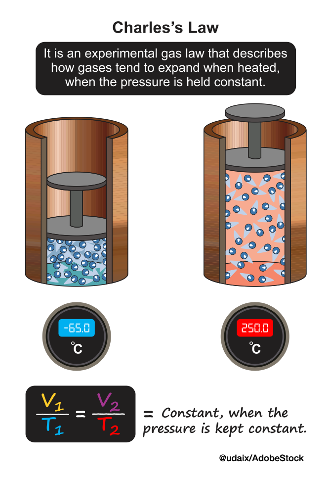
High temperatures cause flue gases to expand significantly because increased thermal energy boosts gas molecules’ kinetic energy, making them move faster and spread out. This principle, described by gas laws like Charles’s Law, leads to volume increases that necessitate expansion joints in equipment to prevent system damage and maintain integrity. This expansion can create immense stress on combustion systems, requiring specialized components like expansion joints to absorb thermal growth and maintain seals, while the high heat can also induce chemical changes and dissociation, influencing performance in other ways.
For example, can you begin to envision how furnace designers and burner design engineers have to pay attention to component growth while maintaining the critical pressures of the furnace and the burners and heat exchangers? It’s a dance, let me tell you! I believe I pointed out a while back that a 6-inch diameter radiant tube or burner combustor will grow almost an inch in length when running at 1400°F and above. If it’s growing in length, it is also trying to grow in diameter. It’s like trying to produce a constant flow of water at a constant spray rate on your garden hose, all the while the hose is changing dimensions. Not so easy is it?
To sum up, with heat recovery, and then with the addition of flue gas recirculation and high velocity burners, it is really quite remarkable how well many of these systems perform. The firing efficiency of a flue gas recirculation system over a conventional cold air burner can be the difference of 30% fuel efficiency and 75% fuel efficiency! We are talking about some serious fuel dollar savings when that all happens. And now, with recirculation, you are also cutting NOx by better than half as well.
Next time we will talk about how these systems do all of this.
About The Author:
Jim Roberts President US Ignition
Jim Roberts president at U.S. Ignition, began his 45-year career in the burner and heat recovery industry focused on heat treating specifically in 1979. He worked for and helped start up WB Combustion in Hales Corners, Wisconsin. In 1985 he joined Eclipse Engineering in Rockford, IL, specializing in heat treating-related combustion equipment/burners. Inducted into the American Gas Association’s Hall of Flame for service in training gas company field managers, Jim is a former president of MTI and has contributed to countless seminars on fuel reduction and combustion-related practices.
Today’s Technical Tuesday highlights the second installment in a multi-part series by Nikolai Alexander and The Heat Treat Doctor® Daniel H. Herring, diving into the controlled heat treatment strategies required to unlock IN 718’s exceptional high-temperature strength, toughness, and corrosion resistance. From solution annealing and duplex aging to hot isostatic pressing and additive manufacturing considerations, the authors explore how precise process control and equipment selection directly shape microstructure and performance in critical applications.
This informative piece is from Heat Treat Today’sMarch 2026 Annual Aerospace Heat Treating print edition. For part 1 on the history, production, and general applications, read Heat Treat Today’sFebruary 2026 Annual Air & Atmosphere Heat Treating print edition.
Introduction
IN 718 was developed for and is extensively used in the aerospace industry. Today, the superalloy and its modifications are heavily relied upon, including IN 718Plus® (US Patent No. 6.730.264 B2), which is designed for operating service temperature to 705°C (1300°F), approximately 55°C (100°F) above that of IN 718. (IN 718Plus will be the subject of a future article by the authors). This article reviews the heat treatment of IN 718 and the need to control both equipment and process variability. Also discussed is the method of additive manufacturing (AM) to produce component parts and the heat treat challenges it poses, including the need to HIP (hot isostatically press) the material to achieve maximum property benefits.
Heat Treatment of IN 718
Figure 1. Typical vacuum furnace used for heat treating IN 718 | Image Credit: Solar Manufacturing
IN 718 is typically heat treated in a vacuum furnace given that it is a sensitive alloy and easily oxidized. Processing in an all-metal shielded furnace (Figure 1) offers advantages for keeping the parts bright after the aging process, without the need to wrap them.
Graphite-lined vacuum furnaces, often with molybdenum heating elements, can also be used provided appropriate precautions are taken. The furnace must be extremely leak tight with a rate of rise under 5 microns Hg per hour. Processing in vacuum is typically done in the 10⁻⁵ torr range. Argon as a partial pressure or cooling gas is necessary to avoid nitriding or oxidation. An alternative, albeit older technology, approach is the use of a vacuum-purged argon atmosphere box furnace with a retort.
From a metallurgical perspective, the amount, morphology, and distribution of the delta (δ) phase have a great influence on the properties of IN 718. During heat treatment, delta phase is extremely important for optimizing mechanical properties, particularly at high temperatures to control migration and precipitation in IN 718. The delta phase inhibits grain growth (by pinning the grain boundaries) and enhances creep and fatigue performance. However, excessive or poorly controlled precipitation is detrimental to other properties like ductility and fracture toughness.
Optimization of delta phase distribution includes selecting the proper solutionizing temperature, between 980–1040°C (1800–1900°F) depending primarily on nickel content, where the delta phase is stable (and thus precipitates out). Thermomechanical working can also achieve this effect by forming more globular-shaped particles rather than acicular (needle-like) ones (Guan, et al. 2023).
There are a number of heat treatments that can be performed on IN 718, including stress relief, homogenizing, solution annealing, precipitation hardening (aka aging), and HIP.
Stress Relief
Stress relief is typically performed at the mill and is a compromise between the amount of residual stress one would like to remove and the possibly harmful effects to both high temperature properties and corrosion resistance. For wrought alloys, stress relief at full annealing temperature is recommended since intermediate temperatures might cause aging. Hold times are one hour per inch of section thickness. For castings, stress relief is especially important when dealing with complex shapes, which may be prone to cracking in subsequent operations or when dimensional control is important.
Homogenization
Homogenization heat treatment is applied to IN 718 for the uniform distribution of alloying elements and dissolution of detrimental phases after its processing through casting and additive manufacturing (AM) routes. There is a definite relationship between laves phase fraction (i.e., the brittle intermetallic compound formed due to niobium segregation during solidification) and homogenization time at various temperatures 1140–1170°C (2085–2140°F). With an increase in homogenization temperature, the time required for dissolution of laves phase and reduction in laves phase fraction reduces drastically. Also, at a given temperature the reduction in laves phase fraction has been shown to occur with the increase of time (Eliasen and Somers 2010).
Full Annealing
Figure 2. Full annealing of IN 718 alloy bars | Image Credit: Solar Atmospheres, Inc.
The process of full annealing involves complete recrystallization and dilution of all or most of the secondary phases to reach maximum softness (Figure 2).
The process is typically run at 955°C (1750°F) holding one hour per inch of cross-sectional area. If welding is to be performed on the component, annealing should be performed immediately after the welding operation. It is noteworthy that niobium additions help overcome cracking problems during welding.
Solution Annealing
Solution annealing (aka solution heat treating) is designed to dissolve secondary phases to prepare the alloy for age hardening and produce maximum corrosion resistance. An added benefit is homogenization of the microstructure.
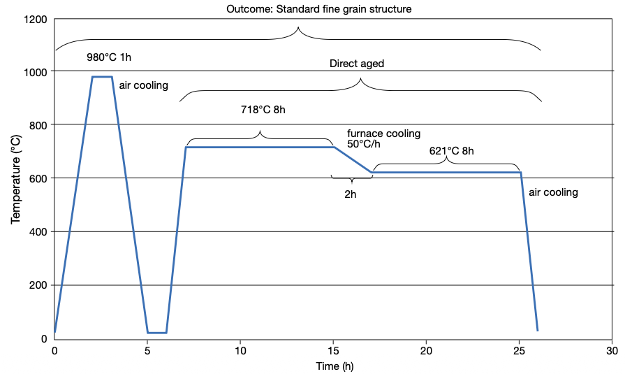
Figure 3. Standard heat treatment cycle of IN 718 | Image Credit: Polasani and Dabhade 2024
A typical heat treatment of IN 718 involves a two-step process — solution heat treating and then age hardening — to control the mechanical property response of the material (Figure 3).
For bar stock, a typical cycle might involve solution annealing at 955°C (1750°F) followed by a 2-bar quench under argon or nitrogen (which can be used if post machining will be performed). This is followed by duplex aging at 730°C (1350°F) for eight hours followed by a vacuum or rapid cool to avoid surface reactions (such as oxidation) and (depending on whether further precipitation is needed) to 650°C (1150°F) and another hold for eight hours followed by a gas fan quench.
Solution annealing at 925–1010°C (1700–1850°F) with its corresponding aging treatment is considered the optimum heat treatment for IN 718, where a combination of rupture life, notch rupture life, and rupture ductility is of greatest concern. The highest room-temperature tensile and yield strengths are also associated with this treatment. In addition, because of the fine grain developed, it produces the highest fatigue strength (Herring 2019).
By contrast, solution annealing at 1040–1065°C (1900–1950°F) with its corresponding aging treatment is the treatment preferred in tensile-limited applications because it produces the best transverse ductility in heavy sections, impact strength, and low-temperature notch tensile strength. However, this treatment tends to produce notch brittleness in stress rupture (Herring 2019).
Aging/Duplex Aging
Figure 4. Duplex aging of IN 718 land-based turbine rods | Image Credit: Solar Atmospheres, Inc.
The aging process is designed to strengthen the material, forming precipitates from the supersaturated solid solution mastic from the solution annealing step.
Duplex aging (Figure 4) involves a two-step heat treatment process and on IN 718 is performed around 730°C (1350°F) for eight hours followed by a vacuum cool or in some cases a rapid cool to avoid surface reactions (such as oxidation) and (depending on whether further precipitation is needed) down to 620°C (1150°F) and another hold for eight hours. This is followed by a gas fan quench. The first soak temperature is intended to initiate precipitation of phases influencing strength and hardness properties. The second soak temperature further refines the microstructure and optimizes the material’s properties based on the phases developed in the initial aging and cooling stages.
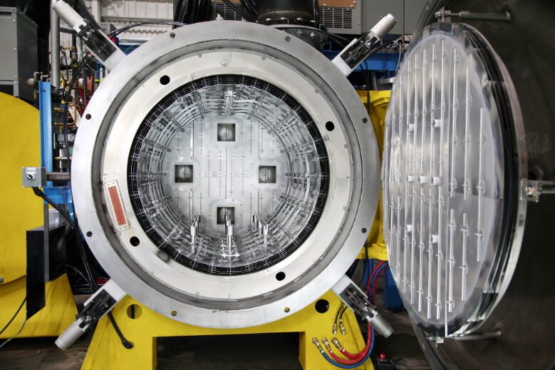
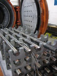
Hot Isostatic Pressing
Figure 5. Typical HIP furnace capable of high temperature/pressure | Image Credit: AVS Inc.
Hot isostatic pressing (HIP) combines high pressure and high temperature to influence the density and microstructure of IN 718 (Figure 5). It is critically important to improve the mechanical strength of shape cast and additive manufactured components to homogenize the as-built microstructure and minimize variation in mechanical properties. It helps to eliminate residual stresses, close pores, close cracks and ensures the material is properly fused (Shipley 2023).
For example, it has been reported (Lee, et al. 2006) that four hours at 2155°F (1180°C) under a pressure of 25.5 ksi (175 MPa) is optimal to improve the microstructure (grain size and segregation) along with tensile properties of IN 718 castings.
Future Outlook
Additive manufacturing (AM) of IN 718 (and superalloys in general) is becoming an increasingly important method for component part manufacturing. It allows complex 3D shapes to be formed without the difficulties inherent in casting, forming, and machining of these alloys.
Electron beam-powder bed fusion (E-PBF) and laser-beam powder bed fusion (L-PBF) have shown great promise for processing IN 718 and other nickel-based superalloys. An absolutely necessary, if not critical, step in the process is post-HIP to heal cracks and homogenize the microstructure.
Heat treating will continue to play an important role in enhancing the properties of IN 718. It will be necessary to update the standard heat treatment requirements (e.g., AMS5662 and AMS5663) to incorporate powder metallurgy (PM) and AM technologies to optimize properties for components made by these methods.
More investigation is needed to optimize solutionizing and aging temperatures for modified IN 718 chemistries. For example, the effect of the cooling rate after aging treatments on the precipitate size and morphology and subsequent mechanical properties of the alloy must be explored in more detail (Eliasen and Somers 2010). And from a heat treatment perspective there is interest in case hardening (nitriding, low-temperature carburizing) of IN 718 (Sharghi-Moshtaghin, et al. 2010, Eliasen and Somers 2010).
Finally, AM processes rely on layer-upon-layer melting. As such, modeling, sensor technology, process temperature monitoring and control of surface displacement improve the build. Emerging trends suggest that the integration of machine learning and artificial intelligence for real-time quality control and process optimization will be a key part of the manufacturing strategy moving forward (Babu, et al. 2018).
References
Akca, Enes, and Gursel, Ali. 2015. “A Review on Superalloys and IN718 Nickel-Based INCONEL Superalloy.” Periodicals of Engineering and Natural Sciences 3 (1): 15–27.
Babu, S. S., N. Raghavan, J. Raplee, S. J. Foster, C. Frederick, M. Haines, R. Dinwiddie, M. K. Kirka, A. Plotkowski, Y. Lee, and R. R. Dehoff. 2018. “Additive Manufacturing of Nickel Superalloys: Opportunities for Innovation and Challenges Related to Qualification.” The Minerals, Metals & Materials Society and ASM International: 3764–3780.
del Bosque, Antonio, Fernández-Arias, Pablo, and Vergara, Diego. 2025. “Advances in the Additive Manufacturing of Superalloys.” Journal of Manufacturing and Materials Processing 9 (215): 1–31.
Chandler, Harry, ed. 1996. Heat Treater’s Guide: Practices and Procedures for Nonferrous Alloys. ASM International.
Croft Systems. n.d. “The Difference between a Wellhead & Christmas Tree.” https://www.croftsystems.net/oil-gas-blog/the-difference-between-a-wellhead-christmas-tree/.
Decker, R. F. 2006. “The Evolution of Wrought Age-Hardenable Superalloy.” Journal of The Minerals, Metals & Materials Society, September: 32–36.
Eliasen, K. M., T. L. Christiansen, and M. A. J. Somers. 2010. “Low-Temperature Gaseous Nitriding of Ni-Based Superalloys.” Surface Engineering 26 (4): 248–255.
Guan, Hao, Wenxiang Jiang, Junxia Lu, Yuefie Zhang, and Ze Zhang. 2023. “Precipitation of δ Phase in Inconel 718 Superalloy: The Role of Grain Boundary and Plastic Deformation.” Materials Today Communications 36 (August).
Herring, Daniel H. 2011. “Stress Corrosion Cracking.” Industrial Heating, October: 22–24.
Herring, Daniel H. 2012. Vacuum Heat Treating: Principles, Practices, Applications. BNP Media II, LLC.
Herring, Daniel H. 2019. “The Heat Treatment of Inconel 718.” Industrial Heating, June: 12–14.
Lee, Gang Ho, Ang Ho, Minha Park, Byoungkoo Kim, Jong Bae Jeon, Sanghoon Noh, and Byung Jun Kim. 2023. “Evaluation of Precipitation Phase and Mechanical Properties According to Aging Heat Treatment Temperature of Inconel 718.” Journal of Materials Research and Technology 27 (Nov–Dec): 4157–4168. https://doi.org/10.1016/j.jmrt.2023.10.196.
Lee, Shin-Chin, Shih-Hsien Chang, Tzu-Piao Tang, Hsin-Hung Ho, and Jhewn-Kuang Chen. 2006. “Improvements in the Microstructure and Tensile Properties of Inconel 718 Superalloy by HIP Treatment.” Materials Transactions 47 (11): 2877–2881.
Loria, Edward A. 1988. “The Status and Prospects of Alloy 718.” Journal of Materials, July: 36–41.
Polasani, Ajay, and Vikram V. Dabhade. 2024. “Heat Treatments of Inconel 718 Nickel-Based Superalloy: A Review.” Metals and Materials International: 1204–1231.
Sharghi-Moshtaghin, Reza, Harold Kahn, Yindong Ge, Xiaoting Gu, Farrel J. Martin, Paul M. Natishan, Arrell J. Martin, Roy J. Rayne, Gary M. Michal, Frank Ernst, and Arthur H. Heuer. 2010. “Low-Temperature Carburization of the Ni-Base Superalloy IN718: Improvements in Surface Hardness and Crevice Corrosion Resistance.” Metallurgical and Materials Transactions A 41A (August): 2022–2032.
Shipley, Jim. 2023. “Hot Isostatic Pressing and AM: How to Improve Product Quality and Productivity for Critical Applications.” Metal AM 9 (3).
U.S. Patent No. 3,046,108.
Acknowledgments:This paper would not have been possible without discussions, guidance and contributions from a number of individuals in both the heat treat industry and academia.
Dan Herring “The Heat Treat Doctor®” The HERRING GROUP
Dan Herring, who is most well known as The Heat Treat Doctor®, has been in the industry for over 50 years. He spent the first 25 years in heat treating prior to launching his consulting business, The HERRING GROUP, in 1995. His vast experience in the field includes materials science, engineering, metallurgy, equipment design, process and application specialist, and new product research. He is the author of six books and over 700 technical articles.
Nikolai Alexander Hurley Intern The Heat Treat Doctor®
Nikolai Alexander Hurley is a young academic, interning with The Heat Treat Doctor®.
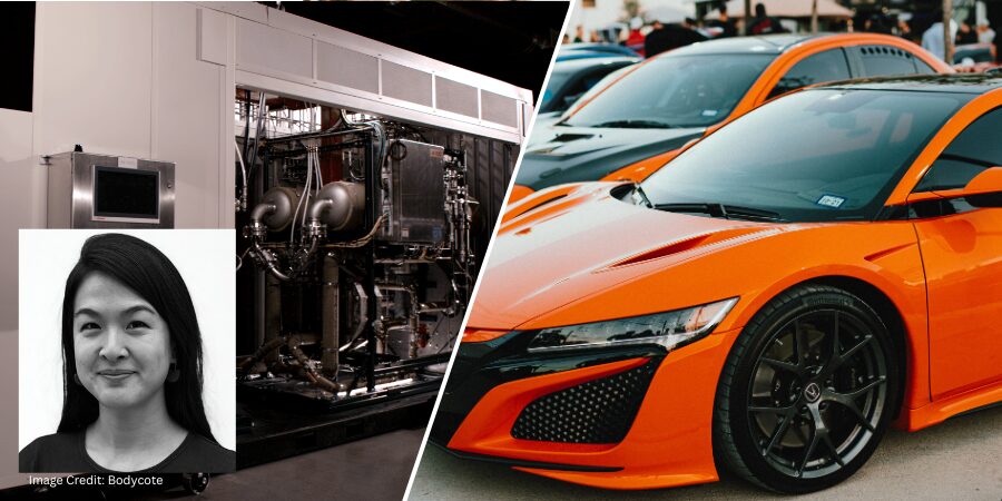
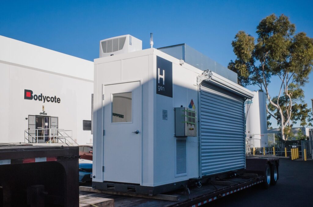
Bodycote, a global provider of advanced heat treatment and specialist thermal processing services, is improving heat treat efficiency and reducing process costs by generating hydrogen on-site at its Rancho Dominguez, California, facility. The system supports controlled-atmosphere heat treatment and brazing operations for aerospace, automotive, energy, and defense applications while reducing reliance on delivered industrial gas.
Hgen at Bodycote | Image Credit: Bodycote
Hydrogen is a critical industrial gas used in Bodycote’s precision heat treatment and surface coating operations, treating metal and metal-alloy components for industrial applications. At the Rancho Dominguez site, processes include annealing, vacuum heat treatment, diffusion bonding, and multiple brazing methods such as hydrogen, inert atmosphere, and induction brazing.
The installed system generates hydrogen from electricity and water at the point of use, eliminating the need for delivered bulk hydrogen and reducing emissions associated with transportation and handling. This approach can reduce related emissions by more than 90% while providing a more stable and lower-cost hydrogen supply.
Click on the image above to read more about Bodycote’s hydrogen strategy in action. Molly Yang Chief Executive Officer Hgen
The hydrogen generation unit, developed in partnership with Hgen, is designed as a compact, modular system that can scale with process demand. Its footprint is 20 times smaller than conventional hydrogen production systems with comparable output, allowing for more efficient use of plant space and reduced system costs.
The containerized module was delivered pre-assembled and installed in less than two weeks, minimizing integration requirements and operational disruption. It also offers an alternative to externally sourced hydrogen. “On-site gas generation avoids the need for expensive gas compression, transport, and storage,” said Molly Yang, chief executive officer at Hgen. She adds that this technology allows Bodycote to reduce gas costs while advancing its sustainability goals.
The installation is expected to pave the way for broader deployment of distributed hydrogen generation across additional sites, reinforcing Bodycote’s long-term energy transition strategy and sustainability commitments.
Press release is available in its original form here. The left half of the main image shows the Hgen module. | Image Credit: Bodycote
In this installment of Answers in the Atmosphere, David (Dave) Wolff, an independent expert focusing on industrial atmospheres for heat treat applications, explores the practical role of argon as a truly inert alternative to nitrogen in thermal processing.
This informative piece on argon’s unique properties, production challenges, and applications — from vacuum heat treating of titanium to powder metallurgy and additive manufacturing —was first released in Heat Treat Today’sFebruary 2026 Annual Air & Atmosphere Heat Treating print edition.
Akin Malas Business Development Manager / Metallurgist Linde
In this column, I’ve invited Akin Malas, business development manager and metallurgist at Linde, to bring his deep expertise in the subject of argon gas. What follows is the fruit of our discussion and continued conversations about this specialized yet indispensable industrial gas in thermal processing applications.
Compared to nitrogen (the industrial gas this column last covered), argon exhibits actual inertness, enabling its use in high-temperature environments and for processing metals that cannot tolerate nitrogen atmospheres, such as titanium and certain high-performance stainless steels. While argon is significantly higher cost than nitrogen, it remains far more economical than helium, another highly inert alternative.
Argon plays a vital role across multiple stages of metal processing, including:
Primary metallurgy: ladle stirring
Powder metallurgy: atomization of metal powders
Additive manufacturing: laser and electron-beam processes requiring inert chamber atmospheres
Vacuum heat treating: backfill gas for titanium and specialty alloys
Argon is used differently than nitrogen in most cases. Inexpensive nitrogen is often used as a utility pressurization gas, for scavenging, and blended with other gases (such as hydrogen); however, argon is most often used in pure form. Nitrogen is considered inert for heat treatment applications except in extraordinarily high temperatures or heat treatment of reactive metals, such as titanium and stainless steels. In this case, using an actual inert gas like argon or helium is necessary. Also, while nitrogen is virtually the same density as air and thus will diffuse throughout a vessel, argon is much denser than air and can be used to form a stratified inert layer.
Linde gas storage tanks | Image Credit: Linde
Both argon and nitrogen are separated from air in a cryogenic air separation unit (ASU), but there are three main factors that make argon much harder to make than nitrogen and thus much more expensive:
Argon is only 1% of air while nitrogen is 78% of air. Argon boils at nearly the same temperature as oxygen, making a separate purification process necessary. Those two factors mean that only the largest ASUs make enough argon to make it worth purifying.
Argon cannot economically be separated from air non-cryogenically (primarily because the percentage in air is so low), so there is no low-cost competition to cryogenic argon. Also, because argon is prized for its inertness, there is much less interest in argon that might be lower purity.
Because argon is made in only the largest ASUs (typically those serving very large steel mills) and because those plants tend to be geographically grouped, shipping distances for argon tend to be much farther than for nitrogen and oxygen, further driving up the costs.
Processors of titanium parts and parts made of some stainless steels, such as the 300 series stainless alloys (SS), cannot be processed in nitrogen-containing atmospheres, because the metals will nitride at heat treating temperatures. Hence these metals may be processed in a pure argon (for Ti) or hydrogen (for SS) atmosphere blends.
We’ll pick up this discussion next month to see what market options are available, particularly in the U.S.
About The Author:
David (Dave) Wolff Industrial Gas Professional Wolff Engineering
Dave Wolff has over 40 years of project engineering, industrial gas generation and application engineering, marketing, and sales experience. Dave holds a degree in engineering science from Dartmouth College. Currently, he consults in the areas of industrial gas and chemical new product development and commercial introduction, as well as market development and selling practices.
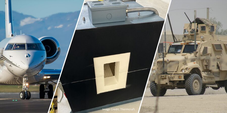
We’re celebrating getting to the “fringe” of the weekend with a Heat TreatFringe Fridayinstallment: a custom split tube furnace engineered for elevated-temperature materials testing highlights how thermal processing equipment is being adapted for complex research environments serving aerospace and defense applications. Designed to support vibration testing while maintaining precise thermal control, the system reflects the growing need to simulate real-world thermal conditions while monitoring material performance.
While not exactly heat treat, “Fringe Friday” deals with interesting developments in one of our key markets: aerospace, automotive, medical, energy, or general manufacturing.
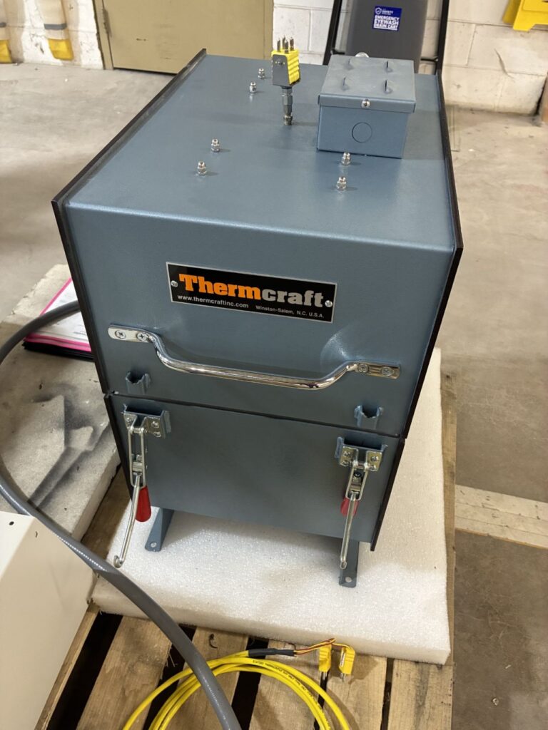
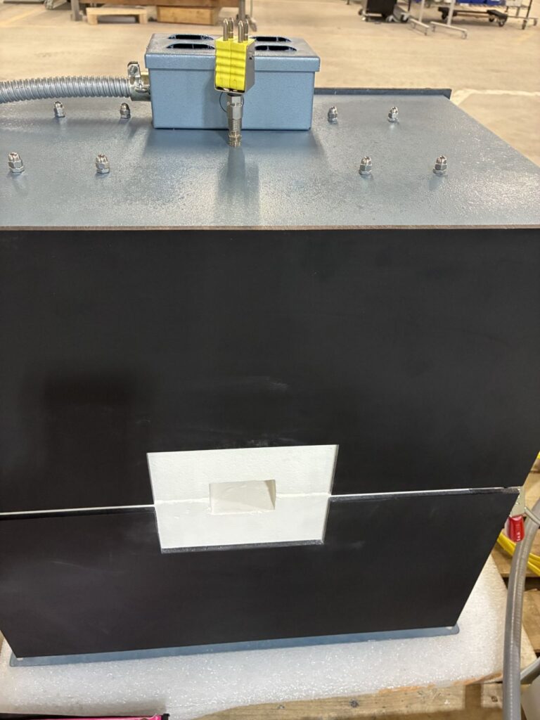
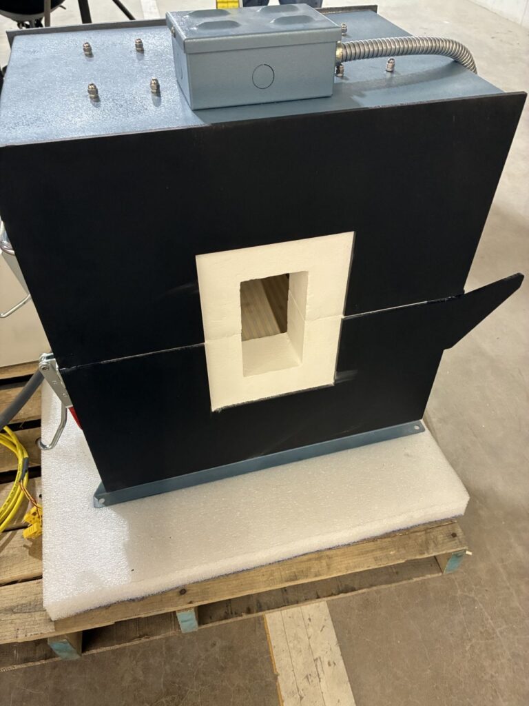
A custom split tube furnace designed for elevated-temperature materials testing demonstrates how specialized thermal processing equipment can be integrated into complex research environments. Thermcraft, a U.S.-based manufacturer of thermal processing equipment serving global markets, has completed the system for an application requiring materials to be tested under vibration while held at high temperature.
The system was engineered to maintain a stable and uniform thermal environment while allowing measurement systems to interact directly with the test sample. The design includes two distinct vestibules — one configured to securely hold the test sample during vibration testing and the other sized to accommodate measurement fixtures and instrumentation.
By working closely with the client during the design process, Thermcraft engineers incorporated custom vestibule geometry, instrumentation access, and system integration features that allow the furnace to function as part of the overall testing platform rather than simply as a standalone heating device.
The system uses a split tube configuration that allows the furnace to open along its length, simplifying sample loading, integration with test rigs, and routine maintenance. A compact external control cabinet provides temperature control and monitoring while enabling the furnace to integrate with the client’s existing testing infrastructure.
Systems like this are commonly used in advanced materials development testing environments, including aerospace and defense materials development, research laboratories, universities, and materials science programs. These applications often require the ability to simulate elevated-temperature service conditions while monitoring material performance.
“Projects like this highlight how important collaboration is between equipment manufacturers and [clients], said Mike Weaver, sales manager at Thermcraft. “Every testing application has its own challenges, and our goal is to work closely with [clients] to engineer thermal systems that support their exact process requirements rather than forcing them to adapt their process to standard equipment.”
Press release is available in its original form here. Additional information provided by Thermcraft.
Heat Treat Today publishes twelve print magazines annually and included in each is a letter from the publisher, Doug Glenn. This letter from the February 2026 Annual Air & Atmosphere Heat Treating print edition celebrates the return of in-person industry events following the disruptions of COVID-19, and previews the lineup of events that Heat Treat Todaywill be involved in throughout 2026 and beyond, such as THERMPROCESS 2027 in Germany and Furnaces North America (FNA) in Indianapolis.
We are five years out from COVID-19 and life is returning to normal, including in-person events. In 2026, Heat TreatToday is starting an Events Division spearheaded by Heat Treat Today veteran, Karen Gantzer. Here’s a preview of the in-person events that Heat TreatToday will be working on in 2026. These events may be important and of interest to you.
Helium Leak Detection Seminars
We are holding four seminars in 2026, one each quarter. If you hurry, you might be able to register for the Helium Leak Detection Seminar scheduled for March 25 in Charlotte, North Carolina. You can register up to the day, including walk-ins. The remaining three seminars are scheduled for June 10 in the Philadelphia area, August 12 near Long Beach, California, and October 15 in Indianapolis, the day after Furnaces North America 2026 concludes. Pricing is very reasonable; standard pricing is $795 for the day, but early-bird registrations are available at $695.
Dave Deiwert, Heat Treat Today’s new favorite vacuum leak detection guy, will be instructing. These should be super-helpful, super-practical seminars. If you have vacuum furnaces, send someone. More information and registration can be found at www.heattreattoday.com/leakdetectionseminar.
THERMPROCESS 2027
This event is not until 2027, but exhibitors should sign up now because the exhibitor registration deadline is May 31, 2026. Heat Treat Today is both sponsoring and helping to create a North American Pavilion at THERMPROCESS. Find out more by reading last month’s Publisher’s Page or by going to www.heattreattoday.com/pavilion.
Heat Treat Boot Camp
Scheduled for September 14–16 in Cleveland, Ohio, Heat Treat Today’s 5th annual Heat Treat Boot Camp is becoming one of the industry’s leading educational events. With a day and a half of classroom instruction sprinkled with some excellent and entertaining networking opportunities, as well as a small (10–12 vendor) tabletop exhibit, Heat Treat Boot Camp has been growing in popularity since its inception in 2022. Last year (2025) saw over 60 attendees. This event has some technical content but is more geared for non-technical individuals who want to understand the marketplace better. Discussions include markets, materials, products, processes, and players. Register early to make sure you or your team get a seat at the 2026 event. Learn more at www.heattreatbootcamp.com.
Furnaces North America 2026
I, alongside the team at Industrial Heating (now out of business), started Furnaces North America (FNA) in 1995 in Cleveland, Ohio. We sold the event to the Metal Treating Institute (MTI) in 1998 after the Las Vegas show. MTI, under the leadership of Tom Morrison, has done a great job growing the show to be one of the top two heat treating events in North America. Heat Treat Today is the exclusive media partner. FNA is in Indianapolis this year, October 12–14. FNA will be the largest and most important technical and commercial trade show of the year in North America. If you’re not planning on being there, please reconsider. More at www.furnacesnorthamerica.com.
Others — And Your Suggestions
There is one other vacuum furnace-related event that we are hoping to do later in the year. More details are forthcoming.
And finally, we’d like to hear your thoughts on what events might be worth doing. Please send your ideas — crazy or sane — to me.
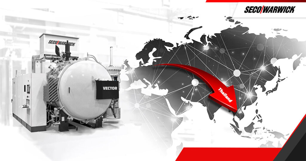
An aerospace manufacturer has ordered a vacuum furnace to support heat treatment of high-performance alloys used in aircraft components, including engine blades. The system is designed to provide controlled atmosphere processing and precise temperature uniformity required for materials such as titanium, nickel alloys, and high-temperature steels.
The vacuum furnace was supplied by SECO/WARWICK, a global manufacturer of thermal processing equipment with locations in North America, to a Thai aerospace manufacturer expanding its production capabilities. The order includes a single-chamber Vector® vacuum furnace intended for heat treatment and vacuum brazing applications.
The furnace features a working chamber measuring 900 mm x 900 mm x 1200 mm, enabling the heat treatment of larger components. It is designed to support high vacuum processes while maintaining charge purity, with solutions that limit sublimation of alloying elements and reduce contamination within the hot zone — factors that are important in aerospace component production.
“It consists of two Leybold mechanical pumps, a Roots pump, and a diffusion pump. The round heating chamber ensures excellent temperature distribution (±5°C/±9°F), and the cooling system enables rapid gas cooling to a pressure of 6 bar abs. Additionally, the furnace provides precise control of partial pressure of argon and nitrogen, which is crucial for the quality of vacuum and brazing processes,” commented Łukasz Chwiałkowski, sales manager at SECO/WARWICK.
This is the second collaboration between the two companies in Thailand. The client already owns an identical SECO/WARWICK vacuum furnace that supports the production of titanium, high-temperature steel and nickel alloy aircraft engine blades. The addition of a second vacuum is expected to increase production capacity and provide operational flexibility for the aerospace manufacturer’s thermal processing operations.
Press release is available in its original form here.
What does it really take to achieve accurate temperature measurement in the real heat treat production? In this episode ofHeat TreatRadio, host Heather Falcone sits down with Dr. Steve Offley, product marketing manager at PhoenixTM, to explore the science behind thru-process monitoring, thermal barriers, and data logger performance. From cold junction compensation to real-world shop floor challenges, they unpack why lab accuracy doesn’t always translate to production — and what heat treaters can do about it. Tune in to learn how to ensure your temperature data is as reliable as the parts you produce.
Below, you can watch the video, listen to the podcast by clicking on the audio play button, or read an edited transcript.
The following transcript has been edited for your reading enjoyment.
Introduction (00:04)
Heather Falcone: Today we are talking about a feature article coming up in this month’s magazine, Achieving Accurate Measurements in Real Heat Treat Production. Joining me today is author of this piece, Dr. Steve Offley from PhoenixTM, who is also our sponsor for today’s episode.
Steve is a product marketing manager at PhoenixTM with responsibility for both strategic product management and global marketing of the company’s thru-process temperature, optical profiling, and TUS system product range. Steve joined PhoenixTM in April of 2018 after 22 years of experience in the industrial temperature profiling market with another well-known company.
The Role of PhoenixTM (2:35)
Heather Falcone: Tell us about your role at PhoenixTM and the role of PhoenixTM, specifically how they provide solutions for the thermal processors out there.
Steve Offley: I am the product marketing manager or product manager for the range of temperature monitoring systems that we offer to the wider industrial space. We provide support for clients in a range of industries who are faced with the daily challenges of using thermal processing as part of their key manufacturing step. We offer unique solutions for those specific applications, because not every application is the same. Our goal is to allow the customer to monitor the temperature of their specific product in some form of heat treatment process.
For instance, we could be offering a solution for the coating market, where a client wants to monitor the thermal cure of a car body. They want to ensure that that car body, as it travels through the curing oven, is achieving the correct temperature, not just in the oven itself, but at the product level. So is each part of that car body achieving the right temperature for the right duration to cure the paint?
Another day we might be dealing with a food processor who, as you can imagine, when they’re dealing with food safety and HACCP requirements, they want to prove that the core of their product, which may be a chicken fillet in a deep fat fryer, is achieving the right temperature, to make sure that it’s safe and it’s an attractive product to eat. And of course, they want to be confident that the consumer is going to be healthy after consuming the product too.
In the buildings and ceramics industry, for instance, we can offer the same sort of solution for the manufacturers of bricks, building materials, tiles, etc., where the process may actually be up to three or four days long where they’re drying the products. But it’s still critical to know what the temperature is at the product level.
Much of our focus is on heat treatment of metals. We are trying to provide different solutions across the whole gamut of the heat treating industry — from primary production, such as slab heat treatment for steel and for aluminum, proving that the raw material has been processed correctly in the furnace, to the finished product.
We are talking about the formed metal product, making sure that that is achieving the right primary metallurgical properties. It needs to do the function it’s going to be used for, from a temperature profiling perspective and also possibly even a temperature uniformity survey (TUS), which is obviously critical in many of the automotive and aerospace sectors of the market where they’re trying to prove or validate the furnace performance.
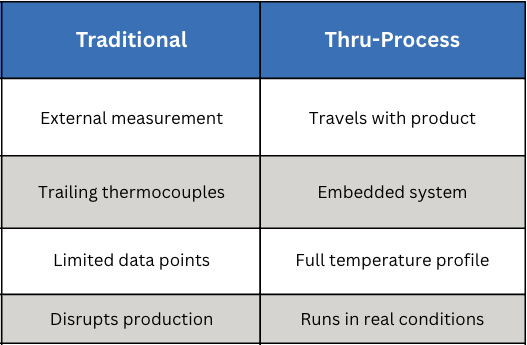
What is Thru-Process Monitoring? (6:08)
Heather Falcone: Can you explain what thru-process is and how it influences the monitoring technology that you’re talking about?
Click the image above for an introduction to the thru-process concept and data logger basics.
Steve Offley: “Thru-processes” is the term that is key to the type of solution we are trying to provide. When we’re talking about heat treatment, there are still many applications where the product may be heat treated in a static box furnace, in which case the traditional technology of using trained thermocouples is probably as easy as any other, whereby you have your field test instrument external to the furnace chamber. The thermocouples are then moved into — or traced into — the furnace, attached either to the product or, if you’re doing a thermal uniformity survey, to a test frame to locate the thermocouples at the desired coordinates within the working zone of the furnace. Then you are collecting the data externally.
I believe it was two episodes ago that you had Dennis from ECM talking about modular heat treatment. He was talking about the challenges of or the increased level of technology associated with moving batches of products around the heat treating cycle in a modular approach.
When you have that type of setup, and even in situations where you may be heat treating in a continuous furnace, the use of a trailing thermocouple becomes difficult at best, impractical and problematic in terms of safety at worst. For the modular approach, you have thermocouples going into different chambers and moving around. There are seals and automated doors in which the thermocouples will be trapped. As such, it’s very difficult to actually monitor the whole sequence of events that may be occurring in the heat treatment sequence.
Traditional vs. Thru-Process Monitoring
This brings us back to the thru-process methodology. At Phoenix, we offer a system that is designed to travel as if it was part of the product basket through the process. The field test instrument, the data logger, has to travel with the product through the furnace.
A data logger in its own right is not capable of going through a furnace if you are measuring at 800°F to 1000°F. One of the key aspects of our system solution is what we refer to as the thermal barrier. It is an enclosure that is used to protect the data logger to allow it to travel through the process. Essentially you encase the data logger inside the barrier and then place it on the conveyor or in the product basket with short thermocouples that are then rooted to the product or to the test frame that’s being moved with the whole monitoring system through the process.
The Importance of Thermal Barrier Design (9:38)
Heather Falcone: The thermal barrier design is really important then, because you’re going to see a variety of environments. How do you protect the data logger?
Steve Offley: That’s the crux of the technology that we’re trying to provide, in so much that there are many different forms of heat treatment or many different forms of thermal processing where we’re trying to provide the protection we need.
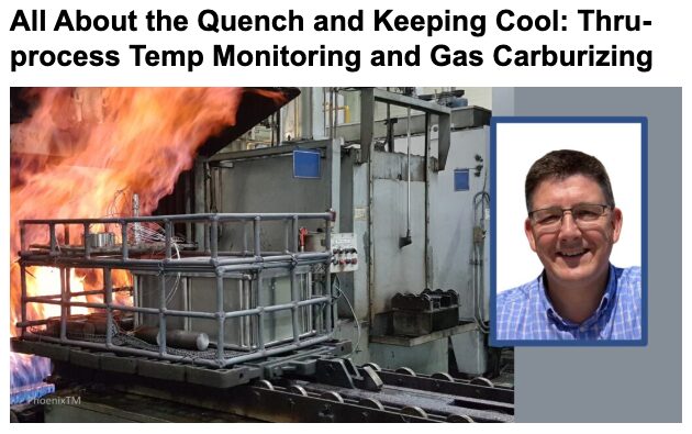
You may have, for instance, a low pressure carburizing process where you’re putting the system into a vacuum furnace, and then you may have a high pressure quench at the end. You have to protect the logger and not just from the temperature criteria inside the furnace, but certain things like pressure changes, which can distort the equipment. That is one design barrier, which would give additional protection to prevent any distortion or compressional damage to the barrier.
Click on the image above to find a real-world companion to Dr. Offley’s barrier design examples, covering oil and water quench protection in practice.
There may be some circumstances, like with a T6 aluminum process, where you have sent the system through the furnace, you then got a water quench, and now in the thru-process principle, the equipment has to go through all aspects of the process. You therefore have to have a design in which the system can tolerate both the heating process, but also the rapid cooling going into the water.
You may also have a situation where you have an Endothermic carburizing furnace with an integrated oil quench. The same approach applies. You are going from a hot environment and then rapid cooling. You are not only protecting the logger from the damage of the heat, but also the materials, like the oil or water in the water sequential and oil quench scenario, so as to not damage the fairly sophisticated electronics of the data log.
There is a lot of science and technology involved in designing unique solutions to meet the specific requirements of the applications. In most cases, we are working with the client from their working spec to develop unique solutions that will meet their unique requirements.
Protection and Accuracy (13:36)
Heather Falcone: When we’re talking about actually monitoring the surveys, what special measures are you required to design the data loggers with that provide accuracy?
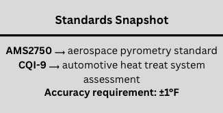
Steve Offley: By the very nature that we are sending the data logger through the furnace, we have to be careful that we are not only protecting the data logger from physical damage, which is possible if we do not get the thermal barrier design correct. But we also want, at the end of the day, to guarantee that we are achieving the accurate data that we need to make sense of the profile information that we are getting. Because at the end of the process, you either have the thermal fingerprint of your process or if you’re doing temperature uniformity survey, you have the readability of the data at the respective test levels. According to the standard CQI-9 and AMS2750, the accuracy of the reading or the field test instrument has to be within ±1°F.
The purpose of the barrier is to not only protect the data logger from damage, but keep the data logger at a working temperature that allows the accuracy of the reading that conforms to the standards that you are working to.
There are different designs of thermal barriers that we can offer. The basic design is what we refer to as the microporous insulation technology. This is basically a dry barrier whereby the insulation slows down the penetration of the heat to the core of the barrier where the data logger is. But at the center of that barrier, there will be a device that we refer to as a heat sink. There’s a eutectic salt inside the heat sink, which will transfer its physical state from a solid to a liquid at a nominal temperature. It’s 58°C where the transfer occurs and that will maintain the temperature at that working temperature.
For longer processes, you may want to use a thermal barrier that uses what we call a phased evaporation protection methodology. In simple terms, it involves the use of water, which is able to absorb very large amounts of energy and heat, and obviously will boil at 212°F (100°C). While it’s maintaining that boiling state, it will maintain the temperature of the thermal barrier and the data logger inside it. So we can actually offer a high temperature data logger that is capable of operating safely at 212°F for long periods time and still be protected.
Thermocouple Use (17:00)
Steve Offley: As long as the barrier provides us with that thermal protection and the logger is working within its operating range, we are fairly safe. That being said, we have to be a little bit careful when we consider the technology of the thermocouple, because there’s some fairly serious restrictions on thermocouple use, which many people may or may not be aware of.
Many people know that the thermocouple technology was developed by Dr. Seebeck back in about 1821. He was a German physicist who discovered the fact that if you had two dissimilar metals connected at a junction or a point, at a particular temperature, those two dissimilar metals would create a millivolt reading, and that millivolt reading would be proportional to the actual temperature that those two dissimilar metals were experiencing. Hence the theory of the thermocouple.
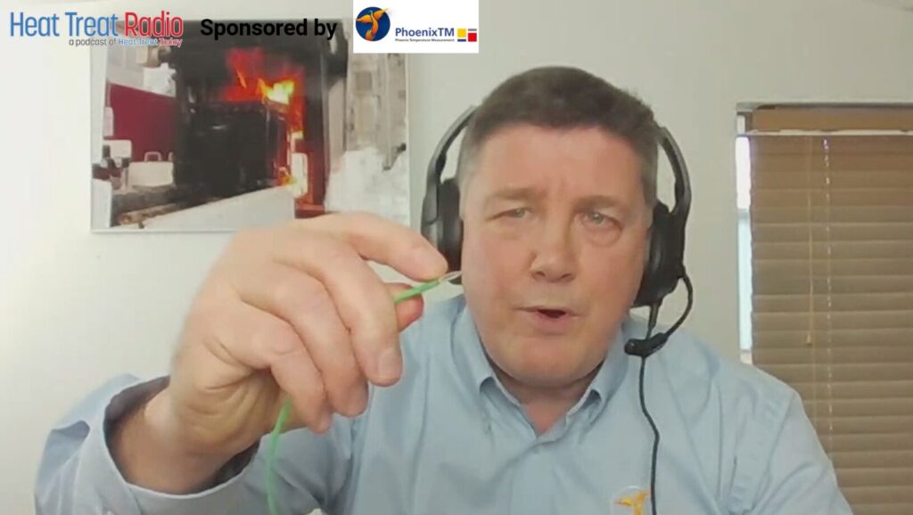
Dr. Steve Offley showing the aluminal and the chromal leg of a type K thermocouple.
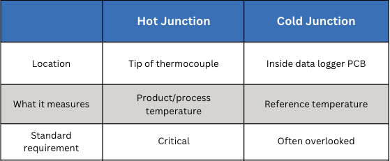
The way the thermocouple works then is that that millivolt can be cross-referenced to a calibration table or a voltage table to determine the temperature reading that the sensor. This is what we refer to as the hot junction, the very tip of the thermocouple. It’s critical that that point is where you want the measurement to be made.
What is often missed is the fact that with a thermocouple, although the hot junction is critical, there is another junction that is even possibly more critical and sometimes overlooked — the cold junction. The thermocouple does not actually record an absolute reading, it’s a ratio between the hot junction and the cold junction. The cold junction of a thermocouple is where the actual thermocouple materials, the two dissimilar metals, join what we refer to as the copper connection. This tends to be where, in the data logger or the field test instrument, the electronics make the physical measurement or process the actual reading from the thermocouple.
If you have a fixed data logger like we have at Phoenix, whereby you would designate the type of thermocouple you were plugging into the data logger — this is a data logger with 20 channels and it’s a type K — I would plug my thermocouple simply into that connector. The cold junction is not in this case at the point where I’m making the connection on the data logger. It is actually inside the logger because there is another wire that goes from the socket to the PCB board where the measurement is actually taken.
Inside the data logger, there is a connector block where the thermocouple wires from the thermocouple sockets will all join the PCB board where the measurement is taken. That’s the location where the cold junction measurement is taken. So, we have our hot junction at the end of the thermocouple, and we have our cold junction inside the data logger.
A side-by-side comparison of the two critical measurement points in any thermocouple circuit: hot junction vs. cold junction.
For some data loggers, that connector or that coal junction may actually be on the outside of the data logger, if it’s a universal connector. So it’s important that you understand where that cold junction is in-situ within your technology. The importance of the reading is the fact that you have a ratio between the hot junction where you are measuring the product and the cold junction where that physical measurement is being referenced inside the data logger.
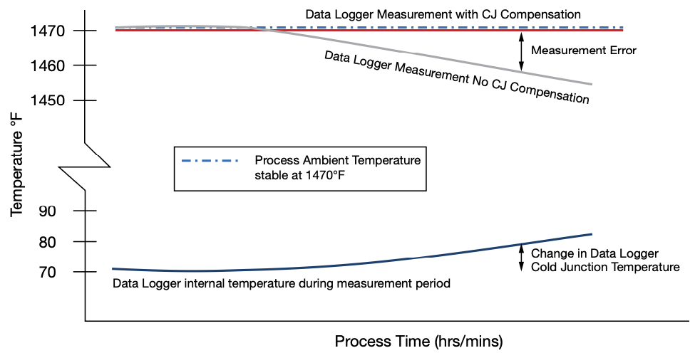
You can imagine, therefore, if the data logger temperature changes, that change in data logger temperature can actually affect the reading you are taking inside your process. That is why it is important to either understand that and make changes so it’s prevented or do what we refer to as cold junction compensation.
Cold Junction Compensation (22:35)
Steve Offley: Inside the data logger, if you are going to compensate for that temperature difference, the data logger is protected up to a physical temperature. But the temperature is going to change. So that cold junction is going to change as it travels through the processing in the way that we do our measurements for thru-process monitoring. The logger will rise in temperature. Therefore, we have to compensate for that.
In the center of the data logger where the connection is made with the copper from the thermocouple cable to the copper-copper connection, we have a temperature sensor, a thermistor, which is accurate to 0.18°F. It measures the actual cold junction temperature of the logger, and it will then compensate automatically for that. Therefore, you can guarantee that even when your data logger temperature changes temperature, it’s compensating for that. There will be no drift in the measurement temperature that you are measuring at the hot junction at the product level.
Data logger temperature change over process time, with and without cold junction compensation, measuring a stable process temperature of 1470°F | Image Credit: PhoenixTM, taken from Achieving Accurate Measurements in Real Heat Treat Production in the March print edition of Heat TreatToday.
Heather Falcone: That was the first time that I had read about the cold junction compensation and why it’s so critical, especially when we’re doing TUS activities.
Steve Offley: With TUS, the accuracy of both the data or the field testing instrument, or the data logger and the thermocouple, are critical to the quality of the test data that you are collecting and obviously trying to comply with the very stringent requirements of the AMS and the CQI-9 standards.
In our case, where we are going through the furnace, we have a worst-case scenario because the data logger is naturally going to change in temperature. But even if we take the scenario to the shop floor, and we are doing an external temperature uniformity survey, the data logger that is sitting outside the furnace, cold junction compensation is still critical for that because within a working day, the floor temperature is generally going to be changing.
Events on the shop floor, like opening the furnace activity on the shop floor, are going to change that temperature. I’ve been in many plants where seasonal changes can make a significant difference to the temperature into which you are taking the temperature. It won’t be the first time I’m sure that people have taken equipment out a car after having traveled for many miles in the early hours of the morning only to realize that the data logger temperature may not be at room temperature. You have to be very careful that you have a stable piece of equipment and that the cold junction is working correctly.
It’s important to read the user manual because there’s often a very critical step to make sure that you are either calibrating the equipment in a real-life environment where the temperature change may be, or ensuring sure that your system has got cold junction compensation. Otherwise, what you believe is a true measurement and accurate, may be the calibration laboratory accuracy where the temperature is controlled very, very strictly. In a real life situation, you may not be seeing exactly the same results.
Heather Falcone: It is really important to consider because there are specific accuracy considerations for AMS2750 and CQI-9.
Steve Offley: I often make an analogy to racing. The Formula One racing cars are tuned up to perform highly on a racetrack environment. They can do 200 miles an hour, having been finely tuned, and they work well. If you take that same racing car off the road into the countryside, it is not going to be working quite as effectively.
The same can be said for data logger technology. A data logger that works well in a calibration laboratory and under fairly safe conditions may or may not be working as effectively on the shop floor, particularly when you consider the variation and the challenges that that environment will bring to a measuring system like this.
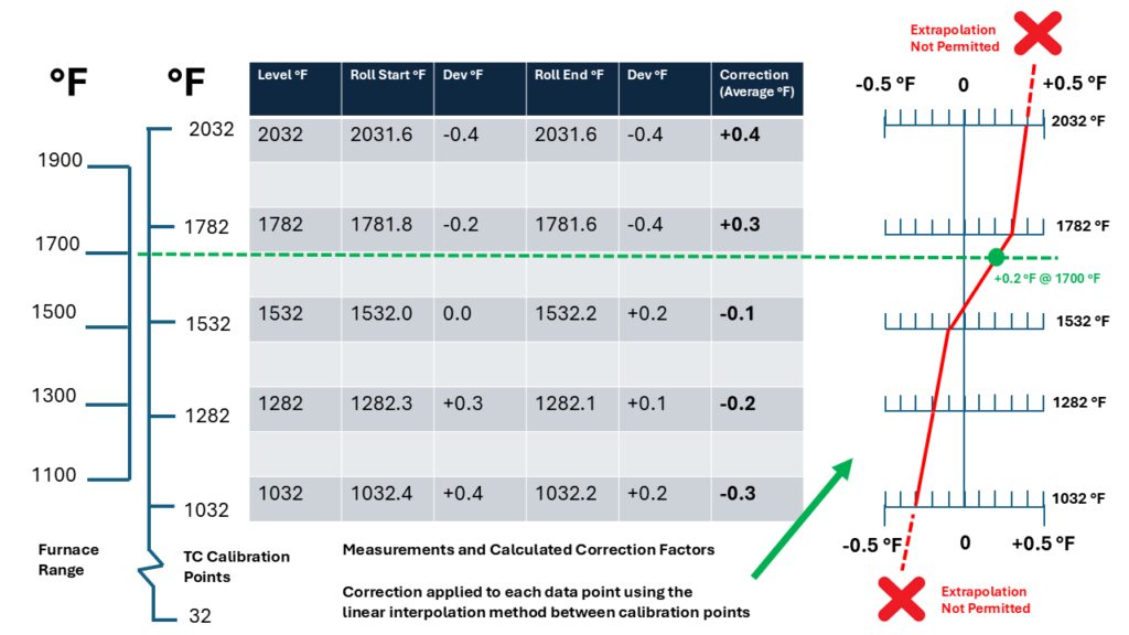
Linear Interpolation Correction Factor Method (27:22)
Heather Falcone: Can you explain how you use the linear interpolation correction factor method, because that’s one of the only that is allowed by AMS2750, and why it is beneficial to your data quality?
Steve Offley: We discussed the nominal requirements for the data log accuracy for its measurement, but for AMS2750, logger correction factors and also thermocouple correction factors can be applied to the test data that you are collecting with your monitoring system.
Firstly, for the data logger, we can create a data logger correction factor file, which basically shows the correction factors that need to be applied to each of the separate channels of the data logger for the data that you are collecting. Inside the data logger, we store the calibration information that was gleaned in the calibration laboratory. That can then generate an automatic calibration template, which can be automatically applied to each one of the channels on the data logger automatically as part of the test routine.
The last thing we want to do is to make some error by transferring raw data manually from a spreadsheet into a piece of software. So, the nice thing about that is that it’s automatically applying the pre-programmed offsets from the calibration routine in the laboratory itself.
Secondly, with the thermocouple, we can take a calibrated thermocouple where there will be a nominal reading at two ends of the thermocouple, and you then get the average correction factor. In some circumstances, people will apply a thermocouple correction factor of one nominal temperature below the test level that they are applying. At Phoenix, we calibrate the thermocouples across the complete temperature range of the data logger. Then, we apply what we call the linear interpretation method. What that means is that between each calibration point, we can calculate, using a linear regression line, the true correction factor at any temperature over the measurement range of the device itself.
The linear interpolation schematic showing thermocouple correction factors across the full calibration range | Image credit: PhoenixTM, taken from Achieving Accurate Measurements in Real Heat Treat Production in the March print edition of Heat TreatToday.
It cannot go beyond the bounds of the upper and lower limit, as extrapolation is not allowed as it says in the standard. But within the upper and lower bounds, we can interpolate linearly between each data point. There is a tight 140° between each point that we can then ensure that we are correcting for or playing the correct correction factor at each temperature from start to finish, not a nominal value over the whole range. In our view, that gives a far more accurate interpretation of the corrected data over the complete working range of the system as opposed to a single nominal value.
Final Thoughts (31:09)
Heather Falcone: We have talked about a variety of topics: thru-processing monitoring, thermal protection at the data logger, the benefits of making sure that you apply cold junction correction, and the specific accuracy considerations that we have to make sure we bundle in all together. What is the big takeaway you want to leave us with?
Steve Offley: Be careful you do not assume that the condition of operation in the calibration of laboratory is going to be reproduced on the shop floor because the conditions are very different. This comes back to the argument for the importance of cold junction compensation. If you are using technology or a data logger, check with the manual for what cold junction compensation should be applied and if there are any steps you need to make to ensure that that is applied correctly on the shop floor. If you do not, there is a high risk that what you think is accurate data may or may not be if you have a situation where your data logger temperature is varying with time, either in process or even on the shop floor with changing environmental conditions.
Heather Falcone: In the end, we want to make sure that we’re making good parts, and this sounds like a great system to make sure that you’re getting as accurate as possible.
Steve Offley: Quality data at the end of the day is essential for you to understand what your process is doing. It’s no good relying on data you cannot trust. Take that extra time to investigate and put steps in place to make sure that you are measuring what you think you are measuring at the hot junction and that the cold junction is being considered as part of that measurement process.
About the Guest
Dr. Steve Offley Product Marketing Manager PhoenixTM Ltd.
Dr. Steve Offley, aka “Dr.O” is a product marketing manager with PhoenixTM Ltd. with 30 years of experience of temperature monitoring in the industrial thermal processing market.
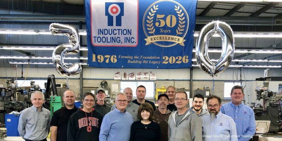
In 1976, what began as a small operation in a 400-square-foot garage grew into one of the most respected names in induction tooling. Today, Induction Tooling, Inc. (ITI), headquartered in North Royalton, Ohio, celebrates 50 years of designing and manufacturing specialized tooling that helps in-house and commercial heat treaters solve complex induction heating challenges across a range of industries, including automotive, aerospace, agriculture, medical, and mining.
Founded by William “Bill” Stuehr, the company was born from a simple observation. While working as a process design engineer at a heat treating company in the mid-1970s, Bill saw clients asking for induction heating that required specialized tooling.
Recognizing the opportunity, he set out on his own. By April 1976, he had delivered his first custom-designed tooling, marking the beginning of a business that would steadily expand over the decades.
Growth came quickly. The company expanded from his home garage to a few different facilities over the decades. In 2005, they finally settled into a 30,000-square-foot facility where they currently house their engineering, manufacturing, and laboratory testing capabilities.
Engineering Solutions for Induction Heat Treating
Induction hardening requires precision, and Induction Tooling has built its expertise around delivering that precision consistently. The company specializes in selective hardening quick-change inductors and related tooling, such as bus bars, adapters, and fixtures used in induction heat treating systems.
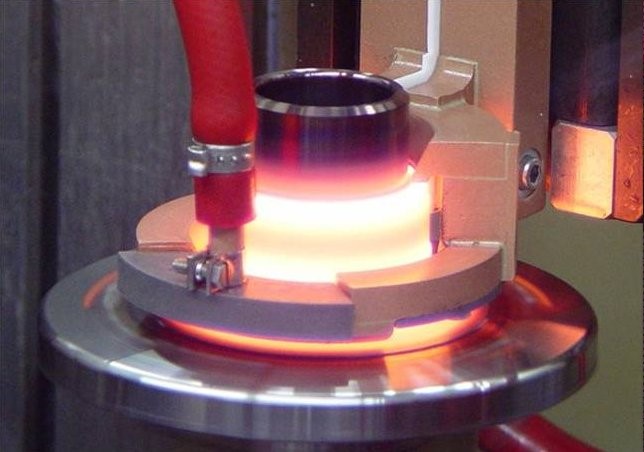
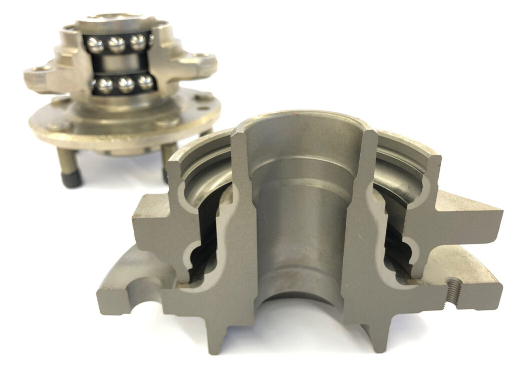
Wheel spindle heating in the laboratory | Image Credit: Induction ToolingWheel hub and spindle, etched pattern | Image Credit: Induction Tooling
By combining advanced design tools with decades of practical experience, the team develops custom solutions tailored to each client’s application. From hardening gears to heating complex shaft and hub components, the team’s engineers work closely with heat treaters to ensure performance, repeatability, and reliability in demanding manufacturing environments. Bringing that stewardship to records, all induction tooling designs have been meticulously maintained since the company’s inception; if ever that custom solution needed to be consulted, the team can and has immediate access to it.
Central to its capabilities is a comprehensive development process that moves from design, machining, and assembly to laboratory testing and metallurgical evaluation. This integrated approach allows the team to test and refine tooling and process parameters before implementation, helping improve quality and meet development timelines. The metallurgical lab also provides a key training experience, allowing designers, engineers, and production workers to see and test the result of their innovation and labor in real-time.
Wheel spindle being selectively hardened and quenched in Induction Tooling’s 3,000 sq ft testing and development laboratory.
A Culture Built on Teambuilding
While innovation plays a major role in their success, the company emphasizes the people behind the work more than anything. Skilled machinists and engineers with decades of experience collaborate across design, machining, and assembly to produce tooling that meets client specifications. This emphasis on teamwork and continual improvement is reflected in the company’s philosophy, which encourages learning, cooperation, and accountability throughout the organization.
The Next 50 Years
As Induction Tooling marks its 50th anniversary, the company continues to pursue the same mission that sparked its founding: inventing and engineering unique tooling solutions that improve induction heat treating processes. Recognizing the integration of automation happening within the industry, the team continues to research ways to further integrate robotics and automation into their processes, including experimenting with additive manufacturing.
For this company, the milestone is not just a look back at half a century of growth; it’s a reminder that innovation often begins with a simple idea and the determination to build something better.
Main image shows Induction Tooling, Inc. celebrating 50 years of innovation and design. If you have any comments or queries on this article, let us know at editor@heattreattoday.com.
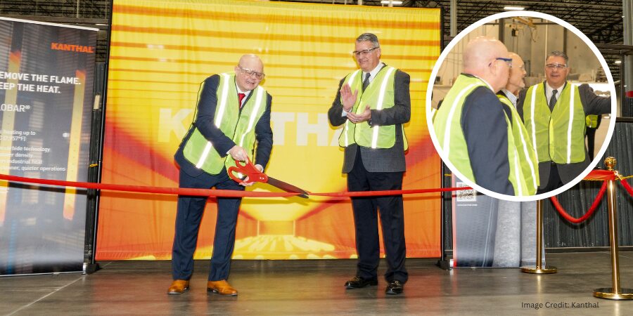
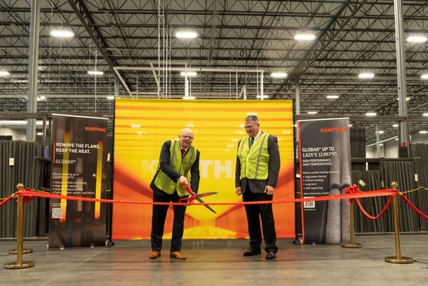
A new service center in Concord, North Carolina, is now fully operational. Kanthal, an Alleima company, added U.S.-based production and service capabilities for silicon carbide (SiC) heating elements used in high-temperature applications across industries such as electronics, glass, and steel manufacturing.
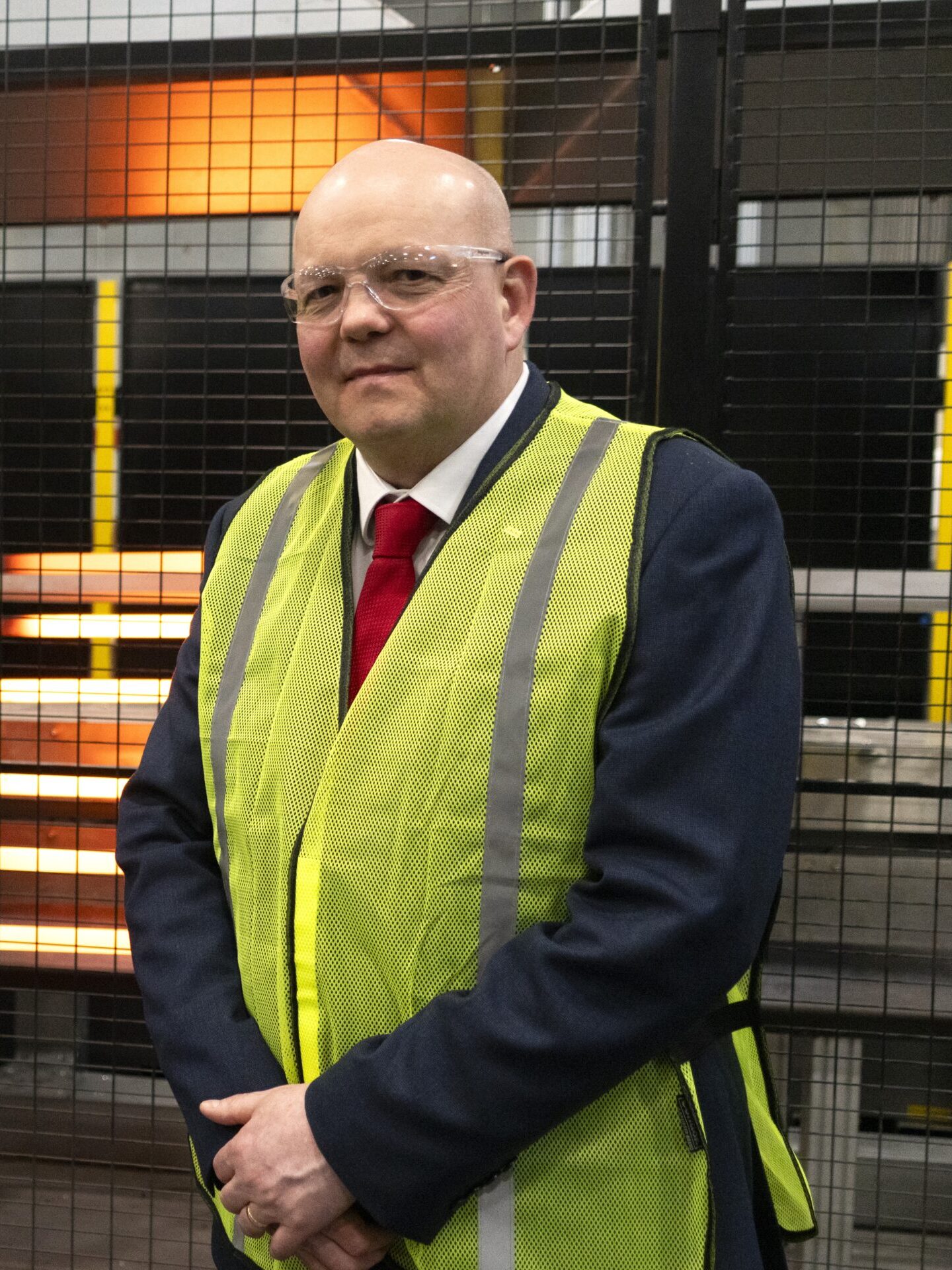
Kanthal leadership celebrating the official inauguration of its new service center located in Concord, North Carolina | Image Credit: KanthalSimon Lile President, Business Unit Heating Systems Kanthal
“This is not just a new service center. We have implemented improvements in Concord that allow us to adapt product configurations based on customer furnace setups and order cycles. The result is a more responsive operation, faster to quote, faster to ship, and better aligned with U.S. [client] needs,” says Simon Lile, president of Business Unit Heating Systems at Kanthal.
Heat TreatToday publisher Doug Glenn attended the ribbon-cutting and open house event to better understand how electrification is shaping high-temperature thermal processing. During the event, attendees toured the Concord facility and discussed how electric heating technologies are being evaluated as alternatives to traditional fuel-based systems. Conversations reflected growing interest in approaches that support improved process control and reduced emissions in industrial applications. “This kind of investment signals a broader shift in how manufacturers are approaching high-temperature processing,” Glenn said. “It’s not just about replacing a heat source — it’s about rethinking how these systems operate in the long term.”
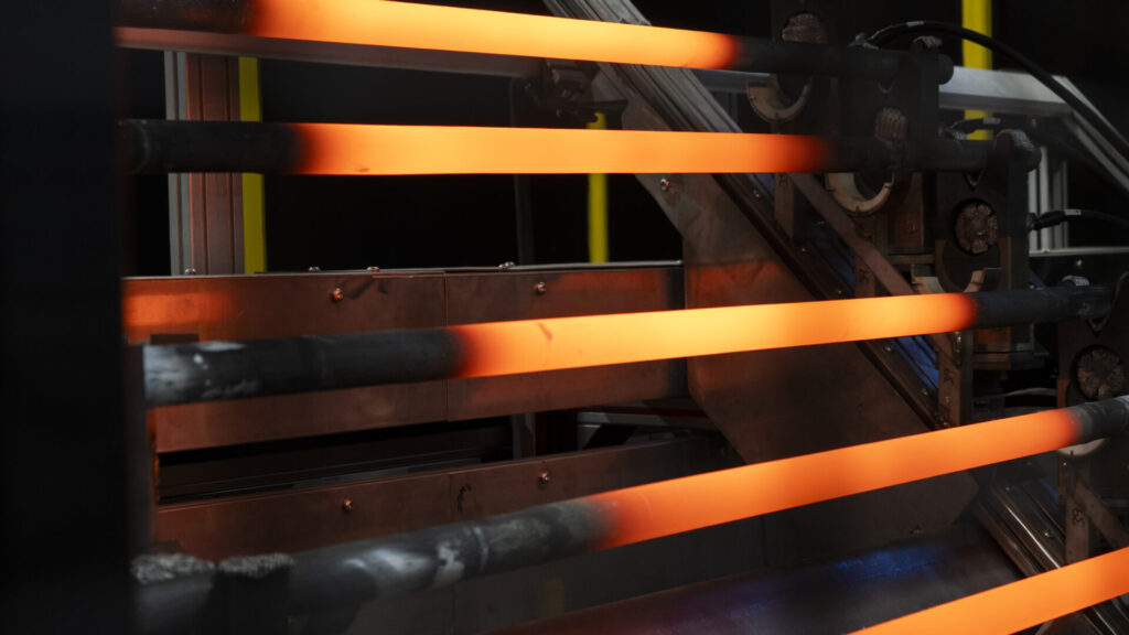
The site includes expanded capacity for Globar® silicon carbide heating elements, which enable electrification of heating processes up to 2950°F and offer an alternative to fossil fuel-based systems. These heating elements can support improved energy efficiency, cleaner operations, and enhanced process control while contributing to reduced CO2 emissions.
Globar® silicon carbide (SiC) heating elements | Image Credit: Kanthal
The Concord service center is part of an approximately $11 million investment that also includes updates to the company’s production site in Perth, Scotland. Together, these developments are expected to increase production capacity by about 40%, while improving lead times and service for clients in the U.S. market.
In 2022, operations from multiple locations were consolidated into the Concord facility, creating a centralized manufacturing and distribution center. The latest investment builds on that foundation to support current client demand.
Press release is available in its original form here. Main image shows the ribbon-cutting ceremony, along with a photo inset of Heat TreatToday Publisher Doug Glenn with President of Business Unit Heating Systems for Kanthal Simon Lile and Production Unit Manager for Kanthal Bruce Dionne.