Heat Treat Today publishes twelve print magazines annually and included in each is a letter from the publisher, Doug Glenn. This letter from the March 2026 Annual Aerospace Heat Treating print edition highlights the growing presence of heat treat-focused podcasts in North American market, spotlighting both The Heat Treat Podcast with Carlos Torres and Heat Treat Radio, including the transition to a new host, Heather Falcone and the continued evolution of digital content in the industry.
It’s amazing to me that there are at least two professionally done heat treat podcasts in the North American heat treat marketplace. There are actually more than two podcasts, but the two I’m speaking of are ongoing and very targeted toward the North American heat treat industry. Check the end of this column for a link to some of the other podcasts I won’t be discussing at length here.
The Heat Treat Podcast with Carlos Torres
Let’s start with the podcast that it not part of Heat TreatToday — The Heat Treat Podcast with our friend Carlos Torres. Carlos is the CEO of TORSA Group Mattsa and a director at Mattsa Furnace Co. in San Luis Potosi, Mexico. Carlos’ video podcast is housed on YouTube (www.youtube.com/@theheattreatpodcast) and has roughly 70 episodes. Carlos cooperates with Super Systems Inc. (SSI) in Mexico, so it is no surprise that Episode #1 from 2021 featured SSI president and all-around great guy, Jim Oakes. Carlos is a very engaging podcast host and has interviewed the likes of Tracy Dougherty, AFC-Holcroft; John Hubbard, former CEO, Bodycote; Chip Keough of the Atmosphere Group; Chad Wright from Wirco; and many other industry notables including Joe Powell, Ben Rassieur, Karen Stanton, Jason Orosz, Jim and Andy Orr, Andrew Bassett, and Trevor Jones.
When Carlos first started his podcast, I joked with him that there was no way he could keep up the pace of turning out good quality heat treat interviews. That was at least four years ago — I was wrong. Carlos continues to do a great job interviewing and posting helpful, timely heat treat content.
Heat Treat Today
The podcast that is a part of Heat Treat Today is Heat TreatRadio. By the time this column is published in March of 2026, Heat Treat Radio will have deployed over 131 episodes since 2016. Initially, the podcasts were strictly audio, but since January 2023, episodes have been video, audio, and transcribed. The list of industry notables is too long, but suffice it to say, it is impressive.
Heat Treat Radio’s new host, Heather Falcone
The BIG news regarding this podcast is that starting last month (February 2026), Heat Treat Radio has a new host, Heather Falcone, former CEO of Thermal-Vac Technology and currently the CEO of Falcone Consulting. Since 2016, I’ve had the pleasure (and responsibility) of hosting the Heat Treat Radio. Heat Treat Today‘s managing editor, Bethany Leone, has been hugely instrumental in the scheduling and production of episodes for the past four years. Both Bethany and I have handed over the reins to Heather, and we are very excited about how the podcast will morph and grow under Heather’s leadership.
By the way, Heather, in her previous life, was interviewed by both The Heat Treat Podcast (Carlos Torres) and Heat Treat Radio. She is, by every measure, an industry legend in her own right.
The nice thing about having Heather take the lead is her ability to “talk turkey” with other industry experts…something I was not able to do being a lowly “publishing guy,” and her creativity and technical savvy when it comes to digital products like audio and video productions. We’re very excited to have Heather on the Heat Treat Today team.
If you have a topic you’d like to see covered on a future episode, or if you know of someone that you think Heather should interview, please reach out directly to Heather at heather@heattreattoday.com.
Whether it’s The Heat Treat Podcast or Heat Treat Radio, I hope you find some of the heat treat audio (and video) helpful.
We've assembled some of Heat TreatToday's resources on forging and metalcasting. Read or listen to what the experts have to say on these important topics in the heat treat industry.
This Technical Tuesday original content piece will help you wade into an introduction of these heat treatment processes. Follow the links to dive deeper into the studies.
The span of articles, radio episodes, and TV clips below are compiled to learn more about forging and casting. Heat treating is developing and changing through the years, and it's wise to keep swimming with the current of information.
Simulating Induction Heating for Forging
What can simulation software do for you? Manufacturers are able to run the software to act upon the steel billet prior to forging. Read more about the process here. The simulation shows results in the metal to help the user best plan for desired results. One of the decisions that can be helped is, "the selection of right forging temperatures for plain carbon and alloy steels to avoid possible damage by incipient melting or overheating."
A Look at Steel and Iron
Dan Herring "The Heat Treat Doctor" The HERRING GROUP, Inc.
Read or listen to this episode of Heat TreatRadio with expert Dan Herring who discusses metals such as stainless steel, tool steel, cast iron, high and low carbon steels, and more. He looks at their production and their uses.
"I wanted to set the stage for it to say that it’s the end-use application by the customer that fuels the type of steel being produced and fuels the form in which the steel is produced," says Herring.
Investment Casting in Turbine Blades
Take a look at how an alumina and silica (quartz) mix are improving metal casting for support rods used in aerospace manufacturing. "LEMA™, a range of proprietary alumina-based materials that provide double the mechanical strength of quartz while providing significantly improved leaching times, compared with typical high purity alumina," provides many benefits for metal casting. Jump into this piece to find out more about this metal casting example.
Direct From the Forge Intensive Quenching
President Akron Steel Treating Co & Integrated Heat Treating Solutions, LLC
In this discussion, expert Joe Powell says, "My thing is to develop a robust process that can be applied and implemented using automation and new equipment with the proper pumps and material handling that is all integrated into a seamless process." He plunges in to talking about immediate quenching pieces in water after heat treating and what they are learning at the forge shop.
Heat TreatTV
Here are a few episodes to keep you afloat while moving into deeper waters.
Click on these two illustrations to watch the full episodes.
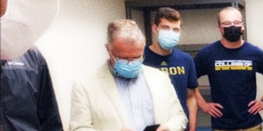
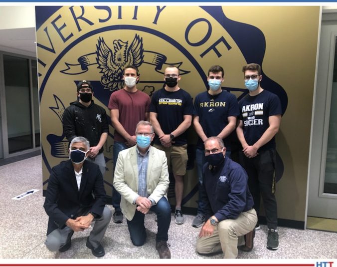
Heat TreatToday was honored with the opportunity to visit the University of Akron and meet several senior engineering students in a Senior Capstone Program focused on a collaboration with heat treat industry leaders.
Applying their academic knowledge and background experience of heat treat and engineering, the students collaborated with and were mentored by Bill Stuehr of Induction Tooling, Inc. and Joe Powell of Akron Steel Treating Co. and Integrated Heat Treating Solutions. The result was an innovative new approach to push the bounds of heat treat. Read about how these students were a part of developing an induction and intensive quench heat treat solution.
By Bethany Leone, Editor,Heat Treat Daily
“You'll never be bored of learning from others. And then, people learn to work as a team and come up with crazy ideas and make that dream a reality! That's [why] this is God's own country. Again, invention country.”
– Dr. Gopal Nadkarni Ph. D., University of Akron
Introduction
At the University of Akron, innovation and invention are being pushed to their limits. Senior engineering students under the guidance of Dr. Gopal Nadkarni have, for the second consecutive year, taken on heat treat theory and practice to test accepted norms in heat treat. But this isn’t just for an academic grade. Their collaboration with professional heat treaters in Ohio makes them engineers on the frontlines of advancing heat treat methodologies and part design.
Left to Right: (Top Row) Dennis Kopacz, Jared McLean, Shadoe Beatty, Tom Benenati, Matthew Yokosuk; (Bottom Row) Dr. Gopal Nadkarni, Bill Stuehr, Joe Powell
Dennis Kopacz, University of Akron ‘21: Age 23. “I’ve always been a problem-solver when I was in class and anything. I loved it . . . As a mechanical engineer, I feel we have a very, very broad spectrum of different avenues we can take.”
Jared McLean, University of Akron ‘21: Age 28. Prior to college, he worked four years in industry and would troubleshoot operations at his former manufacturing employer and was a big part of transitioning them to automation. Jared will return to his former employer and hopes to get his foot back into automation and learn more about design.
Shadoe Beatty, University of Akron ‘21: Age 23. Shadoe shared, “I do enjoy manufacturing. . . but I would like to be a design engineer as well.”[/tab][tab title ="Thomas (Tom) Benenati"]
Thomas Benenati, University of Akron ‘21: Age 22. “Understanding different material properties and how you can get those properties in different ways was really interesting. The induction and quenching project, just put a whole new perspective on that. . . As of right now, I just really like learning I really like. . . Every single engineering process, I’ve just been really interested in.”
Matthew Yokosuk, University of Akron ‘21: Age 23. “I’ve always been a hands-on learner, I’ve always loved to build things. . .So it just felt kind cool that I could go into something engineering where I could just build more.” Matthew is focused on looking for jobs in manufacturing.
Dr. Gopal Nadkarni Ph. D.: Academic professor who initiated the Capstone Senior Project between University of Akron students and Bill Stuehr and Joe Powell.
Bill Stuehr: Bill started his company in his parents’ garage. Now, Induction Tooling, Inc. is helping clients — and students — out of Ohio. Bill’s contributions in both a financial and mentorship capacity were thanked by students from both phases of the project.
Joe Powell: Joe Powell is a leading expert in quenching technology who leads Akron Steel Treating Company and Integrated Heat Treating Solutions in various, innovative heat treat applications. His knowledge on intensive water quenching, molten salt quenching, and gas quenching brought him into the fold, particularly in the second year of this project’s development of the patent pending modified Jominy + HPIQ™ end-quench tester that was developed with co-inventor, Bill Stuehr.
The Guinea Pigs
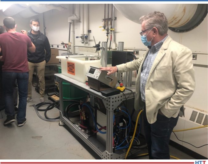
A senior project collaboration between the University of Akron and Induction Tooling, Inc. (ITI) began in the Fall of 2019. Can a heat treater conduct a Jominy end-quench test* by integrating induction heating above the quenching system versus using a furnace and having to carry the sample across the laboratory floor? This was the question that this first group of students and their professor, Dr. Nadkarni, had for Bill Stuehr, president of ITI.
“I remember us telling Bill exactly what [we] wanted to do,” one senior engineer student recalled, “and his response was ‘So what is your budget?’ My answer was simply, ‘Well kind of [. . .] zero.’ I still look back and laugh, because I know that's not what he was expecting to hear. But that didn't stop Bill from wanting to help, and I know most companies would have laughed at us and walked us out.”
With Bill from ITI and Joe Powell from Integrated Heat Treating Solutions, the University of Akron students did design an induction to quench process with new machinery to perform a Jominy end-quench test in one space.
Bill Stuehr with Senior Project 2020: Induction Quench Tub.
“It's a green energy process,” described Stuehr, “so, we can put in an induction unit, heat the rod to a proper temperature using IR [infrared] to control that temperature to the feedback [going] to the induction unit, and then transfer it, drop it right into the Jominy quench, and do your testing. That way, it eliminates heating up a furnace and the energy it takes to [use it] and the dissipated energy that's wasted. And the transfer is almost immediate, because we're going to be heating in the same position [that] we're going to be quenching [the heated sample] with the Jominy tester.”
The students, having learned about traditional and innovative heat treat practices in this hands-on process, walked away with a deeper knowledge of heat treat and a deeper understanding of the equipment that goes into the development of new processes. A graduating student from this first group in 2020 succinctly stated: “Working with Induction Tooling Inc. really made me want to understand more and more about induction heating. This technology, to me, used to be black magic, but now, getting to understand what is happening, it just keeps getting more and more fascinating.”
Taking the Induction Jominy End-Quench Test to the Next Level
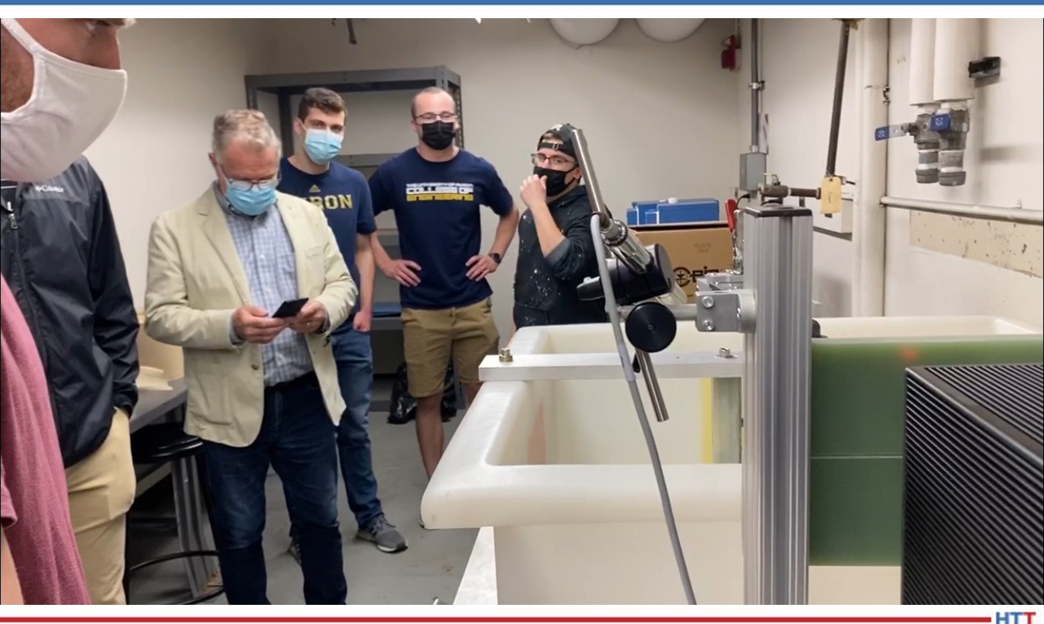
Seeing the success of the first projects, the 2021 seniors and their professional heat treating partners decided to redesign the set-up based on the previous class’s work on integrating these two processes in order to intensively quench the part. Instead of a “drinking fountain,” the team set the goal on 400 PSI “instant-impact” quench on the end of the rod.
Going from a standard Jominy end-quench to an intensive quench with a blast of 400 PSI, said Jared, 2021 senior engineering student, was unthinkable. “At first,” Jared McLean, 2021 senior engineering student reflected, "I thought there's no way. But with the help of Bill and Joe in the design process, [we were] able to capture all that water . . ., and we got great results.” Further, Jared noted, the results mimicked the traditional Jominy end-quench test and “help prove intensive water quenching" can enhance the inherent hardenability for a given alloy.
The team went through a variety of designs, eventually deciding on the use of a different shaped sample rod, versus the traditional flat ended rod, for the test; the high pressure necessitated the use of a lid with one hole to contain the 400 PSI water coming from a “pepper shaker head” and redirect the excess water into the holding tank. In the words of the students, they used an inverted stainless steel “salad bowl” with a hole in the center that went on top of this structure to contain the high pressure quench media. An induction heated Jominy end-quench test rod (of a patent pending design) was lowered into the “salad bowl” hole to be quenched in situ.
Stuehr narrated how Jared, Dennis, and other students developed this construction:
“We [Jared, Dennis, and Bill] tested the [multi-hole] saltshaker [. . .] out in a parking lot on a cold day like today getting wet [. . .]. It didn't work.
“So, we decided, Okay, now what? Let's go down to one hole, so we have a [single-hole] pepper shaker. Now the pepper shaker [. . .] it's got a hole in it, right? And the water comes in through from the pump into the pepper shaker and shoots up and hits the end of this rounded rod. So, we tested it again in the parking lot, just shooting it out there, and [some of the] students did measurements in the tank to measure the flow to see if we could reach the four gallons per minute, at least 400 PSI, because we felt that's about what maximum we're going to be able to get out of this pump.
“We tested in the parking lot, and we're shooting it up to the roof. It looked pretty good. We were measuring the outflow, and we were matching the 4 gpm at about 400 PSI. So, then we took that, and then with the students help, we built a container.
“[We began testing.] First test worked perfectly. Worked perfectly, it just quenched out. You had to hold the handle down because we were afraid of ejecting the Jominy rod from the high pressure, but it contained the quench and did everything it was supposed to do[. . .] hitting the end of the rod and dissipating the quench around this end into this salad bowl, and then delivering the water back into the 55-gallon drum…”
The project was a success, and Dr. Nadkarni accepted the work between the students, Joe Powell, and Bill Stuehr. The students walked away with a better understanding of both traditional Jominy hardenability test standards and had actually developed a new heat treating tool to test the “maximum” hardenability of a given alloy of martensitic steel – all from this “crazy idea.”
2021 Student Reflections on Phase 2
Several of the senior students from the 2021 graduating class noted that their experience was a smooth transition from academics to hands-on heat treat equipment. Jared and another 2021 senior, Dennis Kopacz, said that they were constantly learning on the job; and with the knowledge of Joe Powell and Bill Stuehr, the work transition was smooth, since they had so much to do in such a short time.
Left to Right: Jared McLean, Bill Stuehr, Tom Benenati, Dennis Kopacz, and Shadoe Beatty.
Jared added that they learned a lot using the CNC computer numerical control router controls for the induction heater used to moderate the induction heating temperature and heating rate as well as the quenching process; everything was so precise, and it was incredible to see those types of processes.
“When I first got into the Senior Capstone Project,” Jared reflected, “I had very little knowledge of material science and getting into hands-on and really involved projects; I had to do a bunch of research on what was going on, and I learned a great deal, specifically about how heat treating works.”
These senior engineering students were also surprised at the success of the high pressure intensive water quenching method that Joe Powell and Bill Stuehr introduced to them. “We were in shock,” Dennis admitted, “because we didn't expect it to [work]." The expectation, Dennis continued, was that something would go wrong, like the lid would not be able to clamp down, or the container would leak. But when he and his classmate, Shadoe Beatty, 2021 senior engineering student, witnessed the successful increase in hardness, “it blew our expectation out of the water.”
Not only that, but the passion of this new method struck a chord with several students: “I think the most surprising thing for me was just even with the whole gravity of this project,” Matthew stated. “I think I speak for all of us: we didn't really know that much about material properties coming into this, but quickly, I realized that this project was . . . something almost groundbreaking, even.” He later added, “The opportunity to work with Bill especially has been eye opening to what is possible. Bill and his team at Induction Tooling were so eager to help, and our team is very appreciative of their willingness to support this project. Their knowledge on this subject is invaluable for us graduating engineers.”
The Future
According to Dr. Gopal Nadkarni, each year, the process develops further: “Successive generation of student who [come] in get fired up, red hot; they learn the material properties. They learn the value in manufacturing.” He expressed his hope for changing heat treatment practice, saying that as each new round of students come through, they will raise the bar of heat treatment by working through this one project and developing new standards.”
Rising seniors, Josh Ramirez and James MacKita, are both looking forward to getting into the in-depth co-op as they finish their academics in 2021-2022.
Bill Stuehr said that as one sees the enthusiasm of the students on this project, “one can see underlying aspects of their personalities and how they contribute to the overall process of manufacturing in the United States in the future. This is their future, and this is what we're trying to encourage.”
*Editor’s note: Our friends over at Thermal Processing published an insightful article by D. Scott MacKenzie, PhD., FASM on this test. Find it here.
"A compressive surface stress can benefit bend fatigue performance by reducing the mean stress experienced during service, effectively offsetting the tensile stress generated by the cyclic loading conditions." In this Technical Tuesday by Justin Sims of DANTE Solutions, learn how a simulation program, funded by the U.S. Army, modeled the method of Intensive Quenching®.
This article covers Phase 2 of the project, a follow up to an article that was previously featured on Heat TreatToday. Check out more original content articles in this digital edition or other editions here.
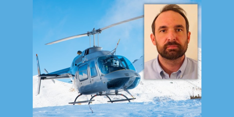
Justin Sims Lead Engineer DANTE Solutions
Helicopter powertrain gearing can be subjected to tremendous loads during service. The high tensile loads experienced in the root of the gear tooth, combined with the cyclic loading conditions inherent in gear operation, can lead to cyclic bend fatigue failures. To improve cyclic bend fatigue performance, low alloy steels are often carburized and quenched. The combination of a high carbon case and low carbon core leads to increased strength and hardness in the carburized case, while maintaining a tough core. In this manner, the case resists wear and can carry a high load without fracture, while the core is able to absorb the energy imparted to it during operation. Besides the increased strength and hardness, the addition of carbon creates a chemical gradient from the surface of the component towards the core. The carbon gradient creates delayed martensite transformations, relative to the low carbon in the core, and is responsible for imparting residual compressive surface stress. A compressive surface stress can benefit bend fatigue performance by reducing the mean stress experienced during service, effectively offsetting the tensile stress generated by the cyclic loading condition
Since the timing of the transformation to martensite is the main driver in the generation of compressive residual surface stresses, it is possible, to some extent, to control the magnitude of the surface stress by changing the quenching process. Historically, transmission gears have been carburized and quenched in oil. However, as more and more attention is paid to improving part performance through processing techniques, other forms of quenching have become available that show promise in increasing surface compressive stresses, and thereby improving bend fatigue performance. Of particular interest, is a quenching method which utilizes high pressure, high velocity water to quench parts.
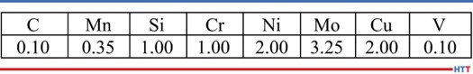
Table 1. Pyrowear 53 nominal chemistry.
Known as Intensive Quenching®, the method was developed by Dr. Nikolai Kobasko as an alternative means of quenching components to achieve deep residual surface compression and improve bend fatigue performance.1–3
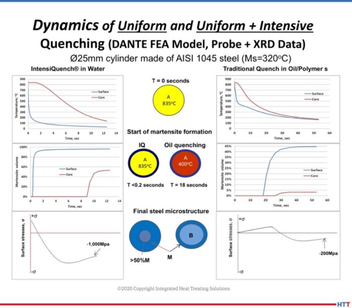
The technology works by inducing a large temperature gradient from the surface to the core of the component. In non-carburized components, the process has been shown to provide an extremely rapid and uniform transformation to martensite in the surface layers, while the core remains austenitic. This creates a hard shell, under extreme compression. As the part continues to cool, the surface is pulled into an even deeper state of compression. As the core transforms, some compression is lost due to the expanding core, but the compression that remains is generally greater than that achieved by oil quenching.4–7
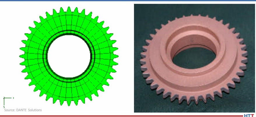
Figure 1. Gear CAD model (left) and actual test gear (right).
To evaluate the possibility of improving bend fatigue of helicopter transmission gears, a program was conceived to compare the bend fatigue performance of carburized gears quenched in oil versus carburized gears quenched using the Intensive Quenching process. Funded by the US Army, the project was comprised of two phases. Phase 1, described in a previous Heat Treat Today article, was a proof-of-concept phase, designed to prove that intensively quenched components could outperform oil quenched components in high cycle bend fatigue testing. Phase 2 then moved to actual transmission gear testing. DANTE heat treatment simulation was used extensively throughout the project to guide processing decisions and understand the mechanisms responsible for improved bend fatigue performance though the creation of residual surface compression. This article will examine Phase 2 of the project.
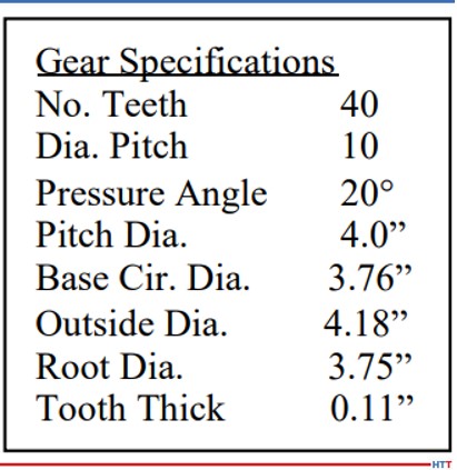
Table 2. Test gear specifications.
Pyrowear 53 was the material of choice for the project, as it is used extensively in helicopter power transmission gearing. Table 1 lists the nominal alloy chemistry for Pyrowear 53, which is a low-carbon, carburizing grade of steel. Figure 1 shows a CAD model of the test gear (left) and a picture of an actual test gear (right); the actual test gear is copper plated to selectively carburize only the gear teeth. The gears were carburized as one batch, and then hardened and tempered to a tooth surface hardness of 59 HRC and a core hardness of 42 HRC. An oil quenching process was used to harden half of the gears and an Intensive Quenching process was used to harden the other half of the gears. Table 2 lists the dimensional specifications of the gear.
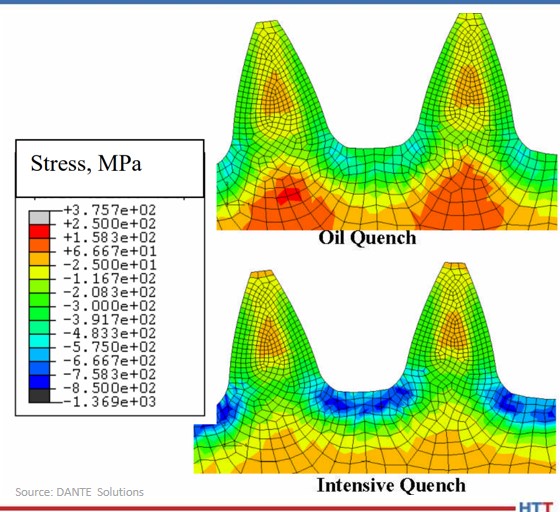
One benefit of using the Intensive Quenching process over a conventional oil quenching process is the development of high residual surface compression. Compressive surface stresses benefit fatigue performance by offsetting any tensile stress generated during loading, effectively reducing, or eliminating, the tensile load experienced by the material. Figure 2 compares the residual stress predicted by DANTE for the test gear subjected to an oil quenching process (top) and an Intensive Quenching process (bottom). It is clear that the Intensive Quenching process induces a greater magnitude of compression in the area of the tooth root, which is the location of most gear bending fatigue failures. The residual stresses present in the tooth flank appear equivalent between the two quenching processes, but the oil quenched component has higher tensile stresses under the carbon case. This could lead to problems should any inclusions or material defects be present in that location.
Figure 2. Residual stress prediction for test gear, comparing oil quench and Intensive Quench.
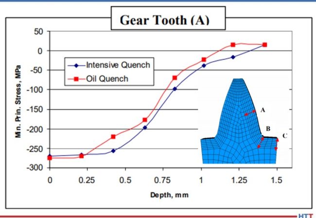
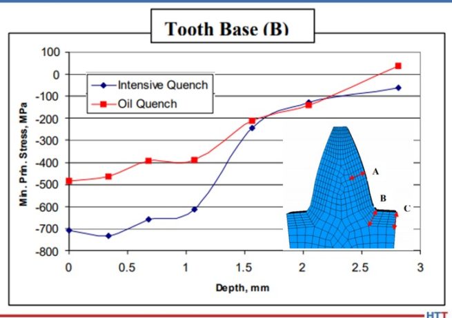
Figures 3 – 5 compare the residual stress profiles of the two gears at three gear tooth locations: flank, root-fillet, and root, respectively. The residual stress profiles for the two processes at the tooth flank, shown in Figure 3, are equivalent, as inferred from the contour plots shown in Figure 2. Both quenching processes generate a surface compressive stress of 275 MPa on the tooth flank. However, the residual stress profiles in the root area of the gear vary greatly between the two processes. Figure 4 shows the residual stress profile at the root-fillet, which is the location of the highest tensile stress during gear service. At this location, the rapid surface cooling afforded by the Intensive Quenching processes creates a large temperature gradient from the surface to the core, allowing more thermal shrinkage to occur after the surface transforms to martensite. The additional thermal shrinkage, combined with the concave geometry of the gear root area, creates additional compressive stresses in this area.
Figure 3. Residual stress versus depth prediction for test gear at point A, comparing oil quench and Intensive Quench.
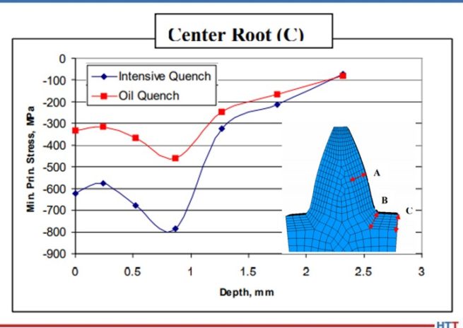
Figure 4 shows that the Intensive Quenching process generated a compressive stress of 700 MPa on the surface of the root-fillet, while the oil quenched gear produced a 500 MPa compressive surface stress in this location. The intensively quenched gear also has a deeper layer of high compression, not rising above 600 MPa compression until after 1 mm below the surface. Figure 5 shows a similar trend for the root, but with an even larger difference between the two quenching processes, since the geometry is even more concave at this location. Again, the gear subjected to the Intensive Quenching process has high compression up to 1 mm under the surface and a compressive surface stress magnitude 300 MPa higher than the oil quenched gear at the root location. The modeling results indicate that the intensively quenched gears should outperform the oil quenched gears in bend fatigue given the increased surface compressive stress present.
Figure 4. Residual stress versus depth prediction for test gear at point B, comparing oil quench and Intensive Quench.
Figure 5. Residual stress versus depth prediction for test gear at point C, comparing oil quench and Intensive Quench.
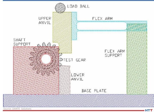
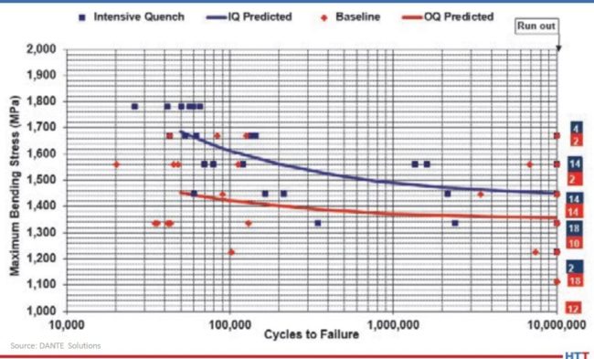
All of the hardened gears were tested at the Gear Research Institute, located at Pennsylvania State University in State College, PA, using a servo-hydraulic testing machine with a specially designed fixture to apply a cyclic bending load to two teeth. A schematic of the fixture is shown in Figure 6. A load ratio of 0.1 was used for all fatigue tests to ensure the gear did not slip during testing by having a constant tensile load applied. The fatigue test was considered successful, defined as a runout, if the gear completed 107 cycles given a certain maximum load. The maximum bending stress, calculated for a stress-free initial condition, was used to compare the two processes.
Figure 6. Schematic of fatigue testing apparatus.
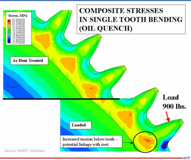
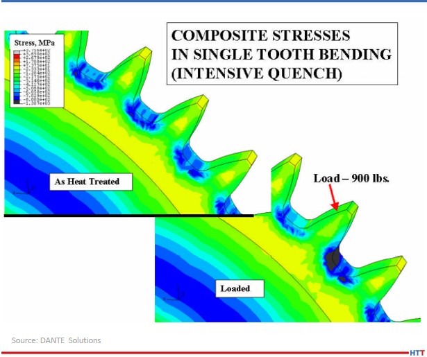
As previously mentioned, the effect of residual compressive stresses during tensile bend fatigue is to offset the tensile stress generated by the load. Figure 7 shows a DANTE model of the test gear subjected to oil quenching showing the residual stress from heat treatment (top) and the stress redistribution during the application of a 900 lb. load (bottom). Figure 8 shows the same conditions for the test gear subjected to the Intensive Quenching process. As can be seen from the two figures, in which the legend ranges are the same, there is substantially more compressive stress remaining in the root-fillet area of the gear subjected to the Intensive Quenching process when the load is applied. This means the effective stress experienced by the intensively quenched gear is less than that of the oil quenched gear, given an identical load.
Figure 7. Stress predictions for the oil quenched gear, showing the residual stress from heat treatment (top) and the stress change when a 900 lb. load is applied (bottom).
Figure 8. Stress predictions for the Intensive Quenched gear, showing the residual stress from heat treatment (top) and the stress change when a 900 lb. load is applied (bottom).
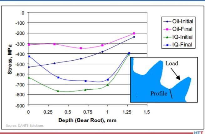
Figure 9 shows the residual stress profile from the surface at the root-fillet for both processes, in the unloaded and loaded conditions. From the plot, a load of 900 lb. generates a tensile stress of approximately 200 MPa, which is offset by the compressive residual stresses. With a 900 lb. load, neither gear sees any tensile stresses during loading, and thus, should runout during fatigue testing.
Figure 9. Comparison of predicted stresses versus depth for the oil quench and Intensive Quench gears in the unloaded (Initial) and loaded (Final) state.
Figure 10 shows the results of the fatigue testing. As expected, the gears subjected to the Intensive Quenching process have an increase in fatigue performance. The endurance limit of the intensively quenched gears is approximately equal to the difference in surface compression, though additional tests should be conducted to confirm this. Regardless, increasing the magnitude of surface compression through a process change can significantly improve fatigue performance of power transmission gearing.
Figure 10. S-N curves for the oil quench and Intensive Quench gears tested.
In conclusion, achieving higher residual surface compressive stresses during hardening of a carburized power transmission gear by way of a process change was shown to improve bend fatigue performance. This was confirmed by the company's simulations, which showed a significant increase in compressive surface and near-surface stresses when the gear was quenched using the Intensive Quenching process, as opposed to an oil quench. The cause of the increased compression was determined from simulations to be due to the combination of martensite formation in the surface layers of the gear and the accompanying thermal shrinkage of the austenitic core, which draws concave geometric features, such as a gear tooth root, into a higher state of compression. The large temperature gradient induced during the Intensive Quenching process is necessary to produce these conditions. Physical fatigue testing confirmed the simulation results, showing a significant improvement in fatigue performance for the gears quenched using the Intensive Quenching process. Accurate process simulation pointed to a heat treatment process change that could be used to achieve increased power density through a transmission as opposed to more expensive and time-consuming design changes.
N. I. Kobasko and V. S. Morganyuk, “Numerical Study of Phase Changes, Current and Residual Stresses in Quenching Parts of Complex Configuration,” Proceedings of the 4th International Congress on Heat Treatment of Materials, Berlin, Germany, 1 (1985), 465-486.
N. I. Kobasko, “Intensive Steel Quenching Methods. Theory and Technology of Quenching”, SpringerVerlag, New York, N.Y., 1992, 367-389.
N. I. Kobasko, “Method of Overcoming Self Deformation and Cracking During Quenching of Metal Parts,” Metallovedenie and Termicheskay Obrabotka Metallov (in Russian), 4 (1975), 12-16.
M. Hernandez et al., Residual Stress Measurements in Forced Convective Quenched Steel Bars by Means of Neutron Diffraction”, Proceedings of the 2nd International Conference on Quenching and the Control of Distortion, ASM, (1996), 203-214.
M. A. Aronov, N. I. Kobasko, J. A. Powell, J. F. Wallace, and D. Schwam, “Practical Application of the Intensive Quenching Technology for Steel Parts,” Industrial Heating Magazine, April 1999, 59-63.
A. M. Freborg, B. L. Ferguson, M. A. Aronov, N. I. Kobasko, and J. A. Powell, Intensive Quenching Theory and Application for Imparting High Residual Surface Compressive Stresses in Pressure Vessel Components,” Journal of Pressure Vessel Technology, 125 (2003), 188-194.
B. L. Ferguson, A. M. Freborg, and G. J. Petrus, “Comparison of Quenching Processes for Hardening a Coil Spring,” Advances in Surface Engineering, Metallurgy, Finishing and Wear, SAE (01) 1373, (2002).
About the Author: Justin Sims has been with DANTE Solutions for eight years and is an excellent analyst and expert modeler of steel heat treat processes using the company's software. His project work includes development, execution, and analysis of carburization, nitriding, and quench hardening simulations. For more information, contact Justin at justin.sims@dante-solutions.com.
Welcome toHeat Treat Today’sThis Week in Heat TreatSocial Media. As you know, there is so much content available on the web that it’s next to impossible to sift through all of the articles and posts that flood our inboxes and notifications on a daily basis. So, Heat Treat Todayis here to bring you the latest in compelling, inspiring, and entertaining heat treat news from the different social media venues that you’ve just got to see and read!
This week, we are looking at mechanical feats of engineering from precision engineered Ferrari parts, to continuous belt furnace epic videos, to dancing robots. What? Yes. Dancing robots. Continue reading for these stories and more in the world of heat treat on social media.
Check out the smooth process behind engineering Ferrari parts. “Highlighting the entire process to craft aftermarket parts, from CAD design, CNC machining, finishing and quality control, the new video also looks at GTO Engineering’s engine building suite as well as restoration of old parts. It also incorporates a range of Ferraris GTO Engineering has been working on and using components supplied by GTO Parts.” Read more about it here.
2. Heat Treat Ready
A few quick tours around your heat treat shops: what have heat treaters accomplished this past year? Have you done anything similar? Let us know and tag @HeatTreatToday on your next post!
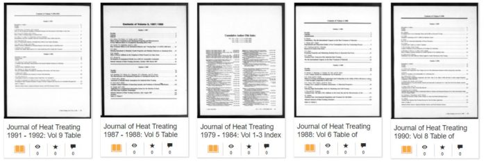
Do you know anyone who has used these heat treating journals? “Journal of Heat Treating is a scholarly journal published in United States focused on Mathematical & Physical Sciences. This collection contains microfilm published between 1979 and 1991. The ISSN is 0190-9177.”
4. Reading and Podcast
Having a lazy Friday? Not to worry. Listen to or read a few interesting insights from around the industry.
ArcelorMittal and the Wheels of Steel
“Ford has been teasing fans with hardcore versions of the Bronco and has been revealing some interesting design characteristics, and now it has announced that industry giant ArcelorMittal has been selected as the sole provider of steel for the 2021 Bronco. Ford will be making use of the company’s Fortiform 980 GI steel, a third-generation advanced high-strength steel, making the Bronco the first car in the world to use this specific grade.” Read more here.
Not everyone can dance, but perhaps there are programs that can help you show off at few parties… At least, your pet robot. “The fun video offers the first glimpse at two Atlas robots working together while also highlighting just how quickly this technology is developing.” A mix of funny and creepy, we’re just going to leave it right here. (“Entire Boston Dynamics robot line-up dances in the new year“)
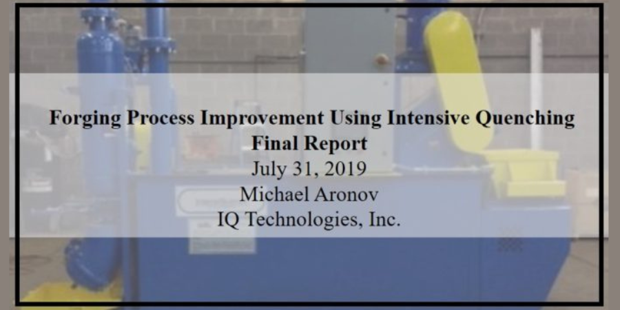
(Click the name above or the image to the right to view and download the report.)
The following report was featured in a Heat Treat Radio episode with Joe Powell, president of Integrated Heat Treating Solutions. In the episode, Heat Treat Radio: Rethinking Heat Treating (Part 4 of 4) — Direct from the Forge, Joe shared the time- and resource-saving potential by intensively quenching parts straight from the forge. This interview was the fourth in a series of episodes in which Joe explained how heat treaters could bring their processes into the 21st century.
An excerpt from the episode: “We can save up to 66% of the energy that’s needed to heat treat that part[…] I’m not going to make a lot of friends in the areas that do this, but if we’re going to compete in the world and make great parts, be lean, save energy, and also have safe carbon emissions, we’ve got to stop heating parts that don’t need to be reheated if you can avoid it[…] there’s a lot of parts that could be made a lot more efficiently if we would quench them right at the trim die.”
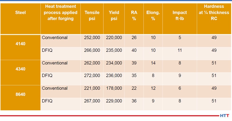
“This report presents results of the application of the Direct from Forge Intensive Quenching (DFIQTM) process to steel forgings obtained in the project’s Investigation, Development, Testing and Implementation stages. For proving and quantifying of the DFIQ process benefits, a portable 600-gallon IQ water tank was designed and built. Forgings of different configurations, ranging in weight from 4 to 80lb and made of plain carbon, alloy and high-alloy steels were subjected to the DFIQ process. DFIQ trials were conducted at three forging shops: Bula Forge & Machine of Cleveland, Ohio, Welland Forge of Welland, Ontario and Clifford-Jacobs Forgings of Champaign, Illinois (both of the IMT Forge Group). The following material mechanical properties were evaluated: tensile strength, yield strength, elongation, reduction in area and impact strength. Data obtained on the mechanical properties of DFIQ forgings were compared to that of forgings after applying a conventional post-forging heat-treating process. Values of heat transfer coefficients in the DFIQ tank were determined experimentally using a special probe. This data was needed for calculating an optimal dwell time when quenching forgings in the DFIQ tank. It was shown that the application of the DFIQ process allows elimination of the normalizing process and, in some cases, quench and tempering processes. The use of the DFIQ process significantly reduces energy consumption and work-in-process handling costs, as well as a production lead-time since a post-forging heat-treating process will be eliminated for many forgings.”
Source: Joe Powell, Integrated Heat Treating Solutions
In this episode, Heat TreatRadio host Doug Glenn talks with Joe Powell of Integrated Heat Treating Solutions in this fourth and final episode about bringing heat treating into the 21st century. This episode covers Direct from Forge Intensive Quenching – forge shops, listen up!
You are about to listen to the 4th and final episode in a series on rethinking heat treatment, with Joe Powell, of Integrated Heat Treating Solutions. You can find the previous episodes at www.heattreattoday.com/radio.
Below, you can either listen to the podcast by clicking on the audio play button, or you can read an edited version of the transcript.
The following transcript has been edited for your reading enjoyment.
DG: Joe, if you don't mind, take us on a 30,000 foot overview of what you've been doing at Integrated Heat Treating Solutions.
JP: What we've been doing for the past 23 years at Integrated Heat Treating Solutions and the last 75 years at Akron Steel Treating is applying heat treatments to parts made by others. We had over 1200 customers on our customer list at Akron Steel Treating and they use various materials. We kind of grew up in the shadow of the Cleveland market, which is the largest market for heat treaters, and there is the largest number of commercial heat treaters in the Cleveland market. This was possibly outnumbered by Detroit at one time, but I still think that we're probably the number one market for heat treating in this part of the country.
What has happened over the last century, in the 20th century, is that heat treating has become very, very good. New equipment has been developed like controls, thermocouples, oxygen probes, vacuum furnaces, vacuum quenching, high pressure vacuum quenching, oil skimmers, new quenchants made with reverse solubility polymers - all of these things have come together and made heat treating very, very good. However, as part of that, there has been a commoditization of heat treatment. That means that heat treating became so good that parts rarely crack or distort unacceptably, and companies have devised methods for correcting the distortion through hard turning, grinding, straightening, flattening, you name it. And the part makers and the heat treaters got along, in a kind of peaceful coalition, to get the parts out the door to the end user.
However, in the 21st century, that is just not good enough. In lean manufacturing, you have to offer an integrated solution for what you're doing. The entire value chain for making a product has to be on the same page; they have to be in alignment. The processes have to be in the proper order. What we're trying to do with Integrated Heat Treating Solutions is bring the last dimension of part design, what we call the Z dimension, to the part makers, their designers, and their material suppliers, so that we present a solution that delivers the optimal amount of value and eliminates the waste from heat treatment, or forging, as we'll talk about today.
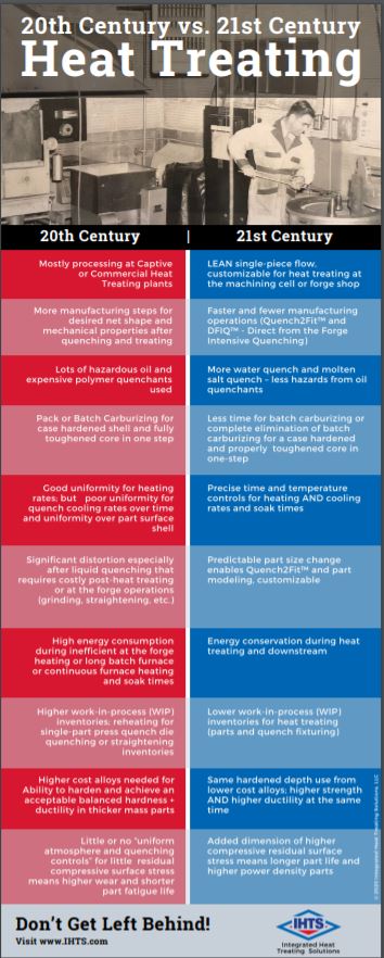
[1] Defense Logistics Agency, "About," https://www.dla.mil/AboutDLA/ [2] DFIQ FIA Technical Committee Presentation, "Evaluation of Intensive Quenching Hardening Process Immediately After Completion of Hot Forging Operations," 2018. [3] Forging Process Improvement Using Intensive Quench, 2019.DG: Right. In these four episodes we've been talking to people about bringing heat treating into the 21st century. On your website, integratedheattreatingsolutions.com, there is a good illustration table that shows what heat treating was like in the 20th century and what it is like in the 21st century. That's basically what we're talking about. Just a quick recap of the previous three podcasts we've done: It all revolves around a customized heating, but more importantly, a customized quenching of materials so that the distortion of those parts is predictable, and that the part design can be altered so that there is essentially no post heat treatment processing. In other words, you can pretty much eliminate grinding or any type of machining, straightening, and that type of thing. Once heat treated and quenched with the technologies that you're talking about, the part is essentially pack and go.
We've talked about several examples, but the two we talked about in the recent podcasts were an 18” bevel gear, which was quite interesting. Then we talked about a fracking pump valve seat, which was also quenched in this way. So today, you and I want to talk about, as you alluded to, the forging industry. We're going to talk about something called (direct from the) forge intensive quenching (DFIQ). If you don't mind, tell us what that is. For those people in the forging industry, what is direct from forge intensive quenching?
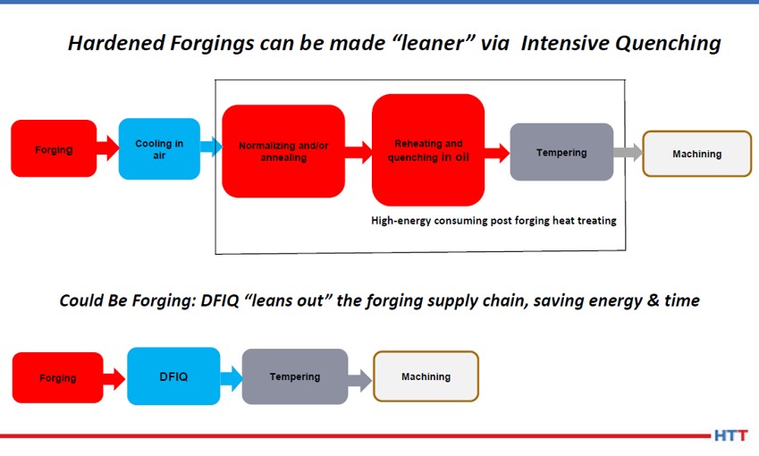
JP: It's the principle that the forging processes use a lot of BTUs of heat to heat up a billet, and then bang it into a shape and get the grain flow going in the direction that will be great for the part mechanical properties. Once that forged shape is attained and the grain flow is attained, the part is usually allowed to cool at the end of the forging trim die line, and those cooling forgings will all cool at different rates. Because they cool at different rates, you have some fast cooling on the surface, the corners and the thin sections; but you have some very slow cooling in the core. At the end of the day, the part needs to be heated a second time in a normalization process, which heats the part to a high temperature and then does a controlled cooling of the part to align the grains of the part and the size of the grains to remove the kind of mishmash of structure that is present in an as-forged part. Then, if the part is going to be hardened at some point, and usually there is a lot of rough machining that goes on to remove the scale from the forging process, machining is necessary to remove the scale from the steel mill that has basically been hammered into the surface of the forging. All of that rough machining is done to basically present a rough machine part that can then be heat treated. So, companies like Akron Steel Treating or the captive heat treats at the forging plants will then heat the part a third time to the austenitizing temperature. If the part is made out of a martensitic steel, they'll quench it, usually in oil or polymer, and then possibly temper it to stabilize the part, and present it to the part maker for final machining, grinding and whatever final processing needs to be done to turn that forging into a useful part with the desired mechanical properties.
Akron Steel Treating doesn't do a lot of forged heat treat. We do some aerospace parts for braking systems for airplanes, called torque tubes, which is basically the hub of the braking system. Those torque tubes are generally made out of forgings which we see after forging, and then see again after 50% of the material is removed. Then the part is heat treated. In those instances, direct from the forge intensive quenching is not going to work.
Direct from the Forge Intensive Quenching
This direct from the forge intensive quench (DFIQ) project came out of a desire by the Forging Industry Association (FIA), which incidentally Akron Steel Treating has been a member since 2012. We've always felt that we could create more streamlined processing as well as a better part with leaner material if we worked together with the forgers and integrated the heat treat process with the forging process. Companies like the TimkenSteel Company have come out with low alloy materials that are forged all the time, and then they do a controlled cooling where they'll actually air cool the forging. With the alloying elements that are in there, they are able to come up with mechanical properties directly from the forge after a controlled air cool. No normalization is needed and no further austenization, or third heating, is needed. Basically, the part is air quenched and tempered right there in a controlled manner from the hot forge.
Some folks in India and Japan have tried several times to do direct from the forge liquid quenching using oils directly from the forge. What they found is that the oil quench catches on fire, and if they can keep it from catching on fire by enclosing the quench under an inert atmosphere, they're still going to have the problem of the very high heat, like 2000°-2200° F, creating a steam blanket of hot oil, or in the case of polymer water, a steam blanket of polymer water mix around the outside of the part. This then produces an inability to uniformly quench the part because the thin sections will very quickly quench out, the thick sections will sit there under a blanket of gas and essentially those two mixes of nucleat boiling - very fast evaporative cooling in the thin sections and a full-blown gas blanket on the thick sections - create a nonuniform shell around the outside of the forging. As that part cools under that nonuniform shell, it is also going to thermally shrink in a nonuniform way. Also, when it cools to the martensite start temperature, it's going to start transformation and face change in a nonuniform way in that shell.
The successes of direct from the forge quenching didn't happen until this project we started in 2015 with the Defense Logistics Agency (DLA), which “manages the global supply chain – from raw materials to end user to disposition – for the Army, Marine Corps, Navy, Air Force, Space Force, Coast Guard, 11 combatant commands, other federal agencies, and partner and allied nations,”and the FIA tech committee members who sat down and asked: “Do you think we can do this in water?” If we can do it in water, we obviously eliminate the fire hazard, but how do we eliminate the boiling hazard, or the boiling issue in the nonuniformity? And that's where we had, at that time, 15 years of experience in applying the intensive quenching process or intensive quench process.
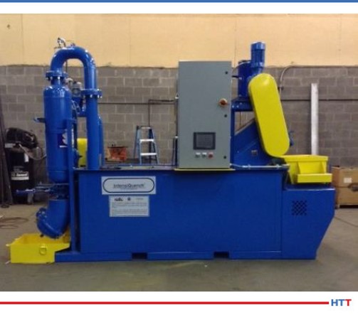
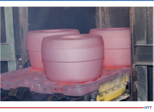
Luckily, John Tirpak, who was then working with the DLA and the FIA as a technical advisor, saw the benefit in giving it a try. We had done lots of parts that people had said, over the years both at Akron Steel Treating and Euclid Heat Treating, couldn’t be done. And we did it. We applied it in the case of the valve seat to ductile iron to replace an 8620 carburized seat. So, we have this great flexibility, we have this great new tool, we just need to use it, or at least try it, at the forge. And that's what the DLA funded. They basically gave us a budget for the building of a prototype unit which was built and is pictured in the final report It shows the test parts that were actually quenched directly from the forge at Bula Forge in Cleveland, and then we moved the prototype unit next to Welland Forge in Canada and finally to Clifford-Jacobs Forge in Illinois.
The upshot of all of this was that once we figured out that if we could remove the film boiling from the outside of the hot forging, we could basically set the shell, and once the shell is set, we get, on most parts and most geometries, a martensite shell that is formed. That martensite shell continues to form down into the layers of the onion below the surface as the martensite temperature is reached and that martensite transformation continues by conduction, very uniformly through the mass of the part. What you end up with is a part that comes out of the quench pretty much like it went through a normalization process and then a third reheating and an oil quench and a temper. We get some self-tempering as well because we interrupt the intensive water quench before the part is fully cooled. Nonetheless, we found in the first phase of testing that parts should be tempered in a tempering furnace to develop the full effects of the tempering process, so that process is still done after the parts come out of the quench. But you eliminate the normalization process and the third reheating for an oil quench and temper that would normally be required.
Examples of DFIQ equipment (Photo source: Joe Powell)
DG: Can you tell us what parts were actually run?
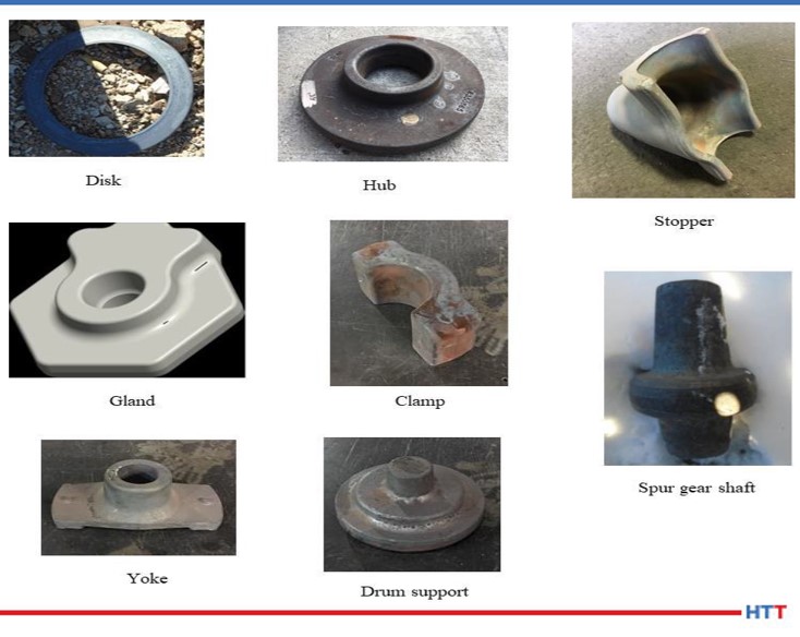
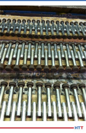
JP: Yes, there were a variety of parts, and they're all pictured in that report. They ranged from a link that weighed, I believe, close to 50 pounds all the way down to a tine that was on a tiller machine (ground engaging tool) that went into a piece of farming equipment. One of the parts in between was a pintle adapter that was basically a mounting post for a machine gun for the Army. This part went through several operations. It's documented in the report, but we basically saved $13 per part to the Army by eliminating the multiple steps that took place after forging and just incorporated it into an integrated heat treating solution right there at the trim die.
DG: How did that look? Let's take the tine, for example. It's stamped out on a forge press. You've got a hot piece of metal put on a forge press stamped out. Then, one at a time, these parts are taken off of the forge press and immediately put in a quench?
JP: After they come out of the trim die, they're still pretty hot - they're still austenitic, and range in temperature from like 1900°F all the way up to 2200°F - and then they go directly into the quench. 15-45 seconds later another one comes out of the trim die and goes down into the shoot and up the conveyor and into a box to await tempering. We time the conveyor so that the dwell time in the intensive water quench is properly timed so that the core still has enough heat to self-temper, but not too hot that it over tempers the part.
DG: I'm curious about the part. After the part comes off the trim die, is it manipulated? Is there a manipulating hand that comes in and grabs it, takes it off, puts in the quench tank?
JP: In the case of the prototype, the manipulating hand was the forger. He came with tongs and provided a very 19th century placement of that part. But, obviously, all of this stuff can be automated and integrated, and with the proper equipment can be done in a way that is seamless from the time the billet is heated all the way through.
DG: Tell me this, that tine again, when the guy took it off the trim die, did he just throw it in an intensive quench tank or was it fixtured?
JP: Picture an elevator platform. It was placed on an elevator and then the elevator went down between two panels that presented water at very high flow to the part and knocked off the film boiling. I should add, the tine was the thinnest part and the enthusiasm at Clifford-Jacobs was very, very high because once they figured out that this worked, the guys on the floor said, “Let's try this part, let's try that part, let's try this part.” And of course, in the first test at Bula Forge, we actually tested at least four different alloy materials and so all of those variables would have to be integrated into the design. I call it the Z dimension of the design. You pick the right material, you have the right forging temperature of the billet, and you don't overheat it. One of the lessons learned in the four-year study is that if you overheat the forging to “help with die life” - that overheating of the forging to 2400°F (almost to the melting point) - the grains blow up. No amount of intensive quenching is going to bring them back. So, you've got to keep the temperature around 2150°F; that's about the maximum in Fahrenheit.
All I can say is that if you maintain a forging temperature uniformly around 2150°F in the billet, we can devise a quenching system that will blow the film boiling off and set that shell in the part in all but the thinnest parts in the prototype. We did about 150 tines in a row with the protype, and then the water heated up because we only had so much chilling capacity in the water tank. But as the water heated up, the quench wasn't as effective, and the tines actually exhibited some cracks when we ran another 150 - that's because there was film boiling in the mounting holes. The lesson learned was you have to have a flow, but you also have to have some pressure in order to instantly impact that part. That instant impact is key in the proprietary processes that Integrated Heat Treating Solutions is developing to bring the next version of the DFIQ unit to make it able to do the thinner parts without cracking.
DG: DFIQ, of course, standing for direct from forge intensive quench.
You've referred to a study multiple times and that study is a 2019 study called,Forging Process Improvement Using Intensive Quench. It looks like that was, as you mentioned, funded by the DLA in either 2014 or 2015. We will make that report available and people can take a look at it. Anyone that is a forger in a forge shop, or a captive forge would certainly want to take a look at that. Would forge press companies be interested in this? Could they build quenches into the actual press itself so that this process could be, more or less, in line?
JP: Yes, absolutely. Again, it is a different paradigm for them. Just like I mentioned before, all the heat treating equipment makers call themselves furnace companies and all the forging equipment makers call themselves press makers or forging die makers. The reality is the process continues and the mechanical properties in the setting of those grain flows happen in the heat treating process; the refinement of those grains happens in the heat treating process which happens in the quenching process. So, again, we need to integrate that quench into the forming equipment. Again, I have no intention, as Integrated Heat Treating Solutions or Akron Steel Treating, of getting into the business of building systems- that's not my thing. My thing is to develop a robust process that can be applied and implemented using automation and new equipment with the proper pumps and material handling that is all integrated into a seamless process.
DG: Let's talk very briefly about the benefits. We've already alluded to quite a few of them, but let's try to enumerate them here. What are the benefits to a captive forge shop in considering a DFIQ type system- why do it? What's the commercial value?
JP: We can save up to 66% of the energy that's needed to heat treat that part. The part comes off the trim die and is cooled in a box or set aside somewhere. Next, it needs to be reheated and normalized. Then, it has to be reheated a third time and austenitized before quench and temper, and that's a lot of energy. And it's also not usually done at the forge plant. It's usually done either at a captive heat treat that is integrated with the forging company or it goes to a commercial heat treat where they use huge continuous furnaces to reheat the parts and quench and temper them. I'm not going to make a lot of friends in the areas that do this, but if we're going to compete in the world and make great parts, be lean, save energy, and also have safe carbon emissions, we've got to stop heating parts that don't need to be reheated if you can avoid it. I'm not going to claim that it works on each and every part and that it should be used for each and every part. I'm just saying that there's a lot of parts that could be made a lot more efficiently if we would quench them right at the trim die.
DG: So, one of the benefits you just mentioned is potentially saving 66%, basically two-thirds, because you don't have to do a second and third heat. What else do we have?
JP: What you can have is better uniformity of mechanical properties. You can also elicit more hardenability out of a particular alloy by having this higher ability to harden with a very, very fast quench. That intensity of quench locks in mechanical properties that are unattainable in a typical oil quench or polymer water quench. One example of that is a forging that we do for a company, in fact it was one of the companies in the study. It's a 44” gear rack- it's 44 inches long, about 5 inches wide and about 4 inches thick. This gear rack is used as a piece of mining equipment and actually 10 of them are used on each side of a tower. This gear rack allows the spinning, drilling rig to go up and down and spin as it is drilling holes in the earth. This part was traditionally made from 4330 material but the end use customer, the people using this piece of mining equipment, said they’d really like to be able to replace and repair these gear racks when they get worn or a tooth gets broken.
If we could do this in the field, that would be great; but with 4330 material, we can't because we have to pre- and post-heat the weld when we replace or repair a tooth in the field. That’s just not practical in some cases, especially if this piece of equipment is on the side of a mountain and it's pretty cold outside. So, is there a way to get field repairability? That's a topic the DLA is very interested in because equipment used by the Army is often times used in very cold environments, so is there a way to repair that piece of equipment without taking it offline or bringing back for repairs?
For this particular gear rack, after they forged it to a rough shape with the gear teeth in on one side and it looked pretty much like a gear rack that was ready for rough machining, they wanted to be able to still get the same mechanical properties from a leaner hardenability steel like 4130 to replace the 4330, so that they could weld it in the field without pre- and post-heating to avoid cracking the part for the weld. They came to us at Akron Steel Treating and they asked if we could this with our 6,000-gallon batch system. We didn’t know. I took a look at the jominy curve for 4330 and the jominy curve for 4130 and said it's going to be close. The thing is 4” inches thick by 5” wide, and I just didn’t know. But I was willing to try. That has always been my favorite answer, “Let's try it.” If it blows up or it doesn't work, I'm going to learn something. You might not be happy because I blew up your part, but I learned a lot and I'm happy and we're going to move on.
So, they gave us five actual parts made out of 4130 and we heat treated them in our 6,000- gallon system. Next, we sectioned them and found that they turned out very, very uniform. They had the right surface hardness all over the part and also had the right core hardness throughout the 44” length. Then they did some field trials, and everybody was happy.
DG: So, in that case, the benefit is potentially being able to replace higher alloy parts with lesser alloy parts, field repairability, lower cost to manufacture the part, and easier to machine. You also talked about the fact that you can do significant energy savings which also potentially shortens the lead time because you're not having to go through two or three processes, but only one. The one thing we haven't mentioned, which I think probably should be mentioned explicitly, although we've alluded to it, is the elimination of some environmentally unfriendly quench media.
JP: It's a water quench. You use just a little of restorentative salt and that's it. It's water.
DG: And obviously you've got better mechanical properties which you've also mentioned.
JP: There's one more chapter to this and it ties back to podcast #2. First of all, we do these parts 15 at a time on racks in our controlled atmosphere furnace and then transfer all of them to the handling cart and quench them in our 6,000-gallon system. We noticed that when they went into the quench, they were straight, but when they came out of the quench, they were all uniformly bowed about 1 inch at the middle of the 44” length. We mentioned to the customer, that when it's time to redo these forging dies, they should bow the forging so that it comes out of the trim die with a 1” bow in the opposite direction. Once it quenches, it will quench to fit and be relatively straight and will avoid the cold straightening operation that is done after heat treat and temper to get the part straight enough so it can be rough machined.
Again, time savings as well as monetary savings and we're not imparting cold strains into the part that has been hardened after heat treat, which is a no-no, because those cold strains can find a discontinuity in the material or an inclusion, and the two combined can, once in a great while, literally blow up as it is being straightened and fly across the room into two pieces. Cold straightening is something you want to avoid if at all possible.
DG: So, again, the benefit there is that you can go back to the part designer and the heat treater.
Let's back out again to 30,000 feet. We're not talking about the gear racks anymore, just talking generally. In your concluding thoughts, what is the main message we're trying to communicate here?
JP: The integration of lean and heat treating and forging. I think bringing all that together, all of that lean thinking and applying it to the part design at the front end, and the material selection at the front end, so that we deliver the most added value with the least amount of waste in the process to the end user.
DG: I would like to wrap up by saying this too, there are a large number of people who are in the Heat Treat Today audience that I think ought to be interested in this. Basically, anybody who is a captive heat treater, manufacturer with their own in-house heat treat who is doing oil quenching, or anything of that sort, and currently doing it in batch, ought to be thinking about contacting Joe to see if they can eliminate that batch process and put the heat treat directly in line. Those are manufacturers.
Also, as we just talked today- the forging shops ought also to be interested in this. Taking forge parts of the finish/trim forge and putting them directly into a quench. But there is one other group that also ought to be interested in this and ought to be talking to you Joe, and that is the heat treat equipment manufacturers who have a stake here. They have a stake here because their current batch processes, if we continue to move down this path into the 21st century, they could be on the cutting edge of providing the type of equipment that can be potentially more inline and more quench type equipment. For what it's worth, I think that's worth mentioning.
JP: Yes. The 21st century of heat treating is moving towards induction heating and individual part by part quenches. That is really the only way to control distortion consistently, and also to effectively get the most that an alloy hardenability has to offer for the end user, in terms of strength and ductility.
DG: If these people want to get in touch with you, Joe, what's the best way for them to do that?
JP: Through the website integratedheattreatingsolutions.com or ihtsakron.com. The other person who is working with me very closely in the FIA technical committee is Rick Brown. Rick Brown is a former executive at TimkenSteel here in Canton, OH. He helped develop a supply chain for making parts out of seamless tubing that Timken made and still makes, and that supply chain included not only cutting up tubing into rings and making parts out of those rings, but also heat treatment, and in some cases, forging. Rick has a wealth of experience. He's a great guy and is one of our Integrated Heat Treating Solutions consultants who helps people at the part makers, part designers and end users get the most value out of the heat treating and forging processes. We're all working towards that goal of moving heat treatment from the 20th century fully into the 21st century.
Heat TreatRadio host Doug Glenn talks with Joe Powell of Integrated Heat Treating Solutions in this third of a four episode series about bringing heat treating into the 21st century. This episode covers the fascinating heat treatment of a fracking pump valve seat.
Below, you can either listen to the podcast by clicking on the audio play button, or you can read an edited version of the transcript.
The following transcript has been edited for your reading enjoyment.
Doug Glenn (DG): We're continuing our conversation with Joe Powell of Integrated Heat Treating Solutions. on rethinking heat treating. I strongly recommend that you listen to parts 1 and 2 of this series as well as today's episode. All three are fascinating. To hear the first two parts, click here.
Today, we’ll be talking about what I think, if you've listened to the first two episodes of this four part series, is a very fascinating, I think, somewhat revolutionary advancement in heat treat.
Today, basically what we want to talk about is a really interesting example of the general concept of what we talked about in session one. I want to review that first session very briefly and ask you a couple of other quick questions before we jump into the example of a fracking pump valve seat, which is where we're headed today. But first, maybe from a 30,000-foot view, Joe, tell us what we're talking about here. If you were to put this in a minute, how would you describe what it is you've been doing over at Integrated Heat Treating Solutions?
Joe Powell (JP): Integrated Heat Treating Solutions (IHTS) is a consultancy that takes 75 years of practical commercial heat treating and applies it to help part-makers make better parts by using heat treating knowledge. We also work with the material-makers who want to get more added value out of a given hardenability material. What IHTS is essentially doing is taking off from the idea that quenching causes the most problems in heating: it causes distortion, part cracking and size change that is unpredictable. That distortion engineering has been part of the ASM and other societies that have had task forces, committees, and various conferences that are dedicated to the control of distortion.
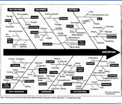
Potential factors influencing distortion (Source: American Gear Manufacturers Association, sourced by Joe Powell)
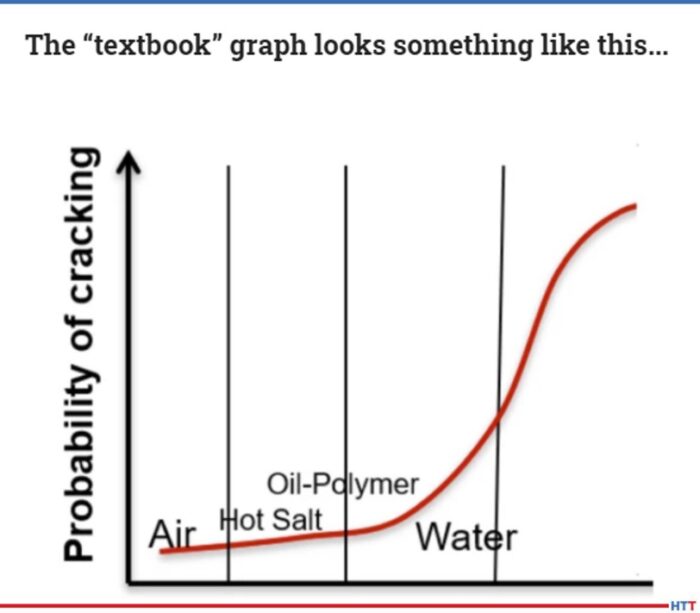
The reality is that the control of distortion has been approached by many, many people, including Dr. George Tautin, who was one of the inventors of the reverse solubility polymers when he worked for Dow Chemical and Union Carbide, and Dr. Kovosko in the former Soviet Union, who was my partner in IQ Technologies starting back in 1999. What we've discovered working with all of these very smart people is that the quench cooling rate and its relationship to causing part distortion or part cracking is a bell shape curve. In other words, if you quench very slowly in air or gas or hot oil or martemper salts, hot salts for austempering, you will not crack the part. But, if you quench faster in brine, water, or even water polymer mixtures that don't have enough polymer in them to act like an oil quench, the cooling rate will become relatively fast. That relatively fast cooling rate will give you a much higher probability of part cracking, until on some parts you'll literally crack every part you put in the quench if it's quenched in water.
If you can create a shell on the outside of the part and quench it 752°-1112° F (400°- 600° C) per second, that shell will literally hold that hot part while the hot core thermally shrinks underneath and pulls that shell under compression. As that thermally cooling shell and hardened shell of martensite goes through volume change and actually increases in volume, the grains are actually pushed up against each other under compressive surface stresses, and that compressive surface stress holds the part like a die. So, regardless of its geometry or mass, that part is going to come out of the quench having cooled by uniform conduction down to its core through that shell in a very predictable shape.
DG: That's exactly what I wanted to get to: what we're talking about here is a quenching issue. It's quenching parts fast enough so that, in a sense, what you're doing is creating a hard outer, immovable shell, if you will, pretty much instantaneously, which holds that part in place while the core cools down to the temperature that is needed.
The quenching media, in one sense, don't really matter. It can be done. The issue is getting that shell formed quickly, uniformly and then holding it at a certain temperature until the core cools.
You and I have spoken in the past, Joe, about a kind of interesting quote which I'd like you to comment on before we get to the fracking pump valve seat example of what we're talking about. Here’s the quote I'd like you to address, “Everyone knows how to heat treat. All you need is a torch and a bucket of water.”
"Every day I learn that in the 23 years that I've been working on heat treat quenching and focusing on that and controlling of distortion, there is always something new, and there is always something new in the field of, what I call, metallophysics."
JP: That's correct. Every machinist you'll ever meet, and even a machining handbook, will tell you how to heat treat a part, and do it quick and dirty. The problem is everybody thinks that it’s because they've heat treated a part in the past, that they know a lot about heat treating, and that is just not the case. There is so much to know, that all I can tell you is that every day I learn something new. Every day I learn that in the 23 years that I've been working on heat treat quenching and focusing on that and controlling of distortion, there is always something new, and there is always something new in the field of, what I call, metallophysics.
DG: Right. It brings me back to a couple of thoughts along that line. One, it's the whole idea that “a little knowledge is a dangerous thing” – we think we know and yet, we don't. You've told me a story in the past and I think it's worth our listeners hearing it, and that is just an abbreviated version of the Jack Wallace story. Again, Jack Wallace, the head heat treat metallurgical guru at Case Western Reserve University, comes into your shop and you tell him, “I can quench these things so super-fast,” and he looks at you and says, “You are a crazy man. It's not possible.”
JP: Actually, it was worse than that. Dr. Michael Aerinoff came from Russia and was telling Jack about this technology that Dr. Kovosko discovered back in the former Soviet Union. So, it had two strikes against it. Not only was it new information and contrary to the idea that the faster you quench, the more likely you are to blow up the part, but it was also contrary to the information, “Hey, we're in the United States. We know all about heat treating and metallurgy!” At the end of the day, this metallophysics twist that Dr. Kovosko put on the dynamics of the heating and cooling process is really the key to understanding and viewing metallurgy from another dimension – the dimension of residual and current compressive stresses that are affecting the part. That's what Dr. Kovosko told us about, and finally, that's what unlocked the ability of the parts that Professor Wallace witnessed being quenched and not cracking.
DG: I would have loved to have been there and seen the eyebrows of Dr. Wallace.
JP: The other two metallurgists who were in the room besides me – two owners of heat treating companies, Wayne Samuelson of Shore Metal Treating at that time and John Vanas at Euclid Heat Treating – both of them basically wrote Michael off as a crackpot because they had heard what professor Wallace had said. I was the only one dumb enough to think, “Well, come on down. If you want to demonstrate some parts, they're either going to blow up or they're not. If they don't blow up, it'll be interesting, and if they do blow up, it will be funny, so let's try it!”
DG I wanted our listeners to hear some of the other people who are now, as I say in quotes “true believers.” You've got Jack Wallace who now believes what you say is actually true. You've also got, I believe, George Tautin, who is kind of the “king of quench.”
JP: Absolutely. He's actually written a book with us. It's an ASTM book; it's publication #64, I believe, and that book tells you exactly how to build the first and second generations of IQ (intensive quenching) equipment. George also said in 2014, after he retired from making polymer quenches, that you don't really need oils or polymer quenches. You can do quenching very nicely with a properly designed quenching system and water, or water and a little bit of salt. That was a pretty strong statement from a guy who literally spent his career making those quenches better.
DG: You had mentioned one other individual, Robert O'Rourke.
JP: Yes, he is a metallurgist with over 30 years of experience with ductile iron. Bob worked with one of the industry giants, Chip Keough,* who founded Applied Process and also austempered ductile iron. Chip's company not only worked with the ductile iron society for many years, but also with Bob O'Rourke, who was one of the principals at the Ductile Iron Society; in fact, he was president back in 2015. At the end of the day, he basically said that we could take this kind of crappy material, ductile iron, and austemper it. Chip made a very good business out of austempering ductile iron at Applied Process and converted many, many parts from either as-cast ductile or even steel parts to austempered ductile iron parts.
That, to me, showed that it's possible to take a heat treating process and apply it to a material and literally create a new material out of as-cast ductile irons. Chip even said, “I know what you guys are doing. When we quench in salt, it's very uniform. There is no film boiling. There is no nonuniformity in the cooling. All you're doing is just kicking it up a notch with higher intensity and knocking off the film boiling with the intensive agitation.” And I said, “You're absolutely right, Chip.” What we did not know at that time was that it could be applied to ductile iron.
DG: Let's jump into this fracking pump valve seat. A couple basic questions. First off, we're talking about a pump that is used in the fracking industry to extract out, I assume, the fracking fluids, and things of that sort.
JP: It's actually to inject the high-pressure water sand. They call the sand a proppant. After the pump has fractured the shale layers, then they inject water and sand to hold up and prop up those cracks in the geology and allow the gas to flow out more quickly.
DG: Good. So, the point is, it is very rugged and the pump takes a beating. What was the problem that the company was having? How did it come to your attention?
JP: The frackers were having to rebuild the pumps every 40-60 hours and replace these valve seats. They had high pressure water and sand flowing through the valves. The valve would open and close under pressure at about four times a second, and that constant abrasion of the valve opening and closing and banging into the seat was causing the seat to wear out. Once the seat is worn, then the pump can't maintain its pressure, and they're not getting anywhere in terms of putting that fluid down in that well, and therefore, making it produce more oil and gas products.
DG: Essentially, you've got fracking companies who are having to replace valve seats and rebuild the valves every 40-60 hours. What was the material that was being used for the valve seat?
JP: For years, these types of seats were made of 8620 carburized steel. They usually start with a forged ring, and then they machine that ring into a valve seat with a taper and a strike face where the valve closes onto the valve seat. That part is generally carburized around 90,000th of an inch effective case step and tempered and then put into the pumps. Again, that case hardened surface is 60–65 Rockwell and wears very, very well and resists the abrasion of the sand and water. Because it's 8620, it has a ductile core underneath the strike face that absorbs the impact of the valve opening and closing on top of it every four seconds under pressure.
You have to have a combination of hard, yet ductile. And you have to have a tough part that resists wear and abrasion.
DG: These guys were using it and still having to replace it every 40-60 hours, so what was your thinking on it and how did you guys help?
JP: A whole bunch of people had tried to put tungsten carbide inserts into the strike face to make the strike face even harder than case hardened material. Then a company came out with a solid sintered tungsten carbide valve seat that costs upward of $500–800 each. You’ve got to remember that there are ten of them in the pump, and they were built as a lifetime valve seat because they actually outlasted the pump block and some of the other parts of the pump. But that was not a great solution because, at that point, you have a seat that's lasting longer than the pump block. You still had to take apart the pump anyway for other things that were worn; it's too good and it's too expensive. If you've got $8,000 worth of seats, you're not going to throw the pump block out because it's worn out, you're going to try to remove those seats.
Large Rolls on Their Way into IQ Tank (Source: Joe Powell)
Again, what they were looking for was a longer life valve seat, not necessarily a lifetime valve seat, but something that would last for all of the stages used by that pump at a certain well. They would move it at the time that the well completely fracked and started to produce and take it back and rebuild it at their shop. They were shooting for 200 hours.
DG: Right. Again, the normal was 40-60 hours with the 8620 material.
JP: Right. Having had the experience with the elongator roll and the ability to make something that was literally so hard they couldn't knurl it, we had to temper those elongator rolls back quite a bit in order for them to knurl them and then use them at the mill. I thought, if we don't temper the valve seat back and just leave it that hard, it should be carbide-like hard, because if a carbide tool can't knurl it, it's pretty doggone hard. We fired up our existing piece of equipment that we had at Akron Steel Treating, a 6,000-gallon intensive quenching tank. We heated the parts and quenched them in that big batch tank, and we got very nonuniform results.
One of the things we did not understand back in 2012 was that ductile iron, because of all the graphite particles that are in there, has a very low thermal diffusivity, meaning that in order to get the heat into it or out of it during the quench, you had to be more than intensive; you had to be, what I call, instantaneously impacting that surface with high pressure water that literally pulls the heat out at a rate that will allow you to get to the martensite start temperature, cool to the martensite start temperature, and form that shell in less than 2/10th of a second – and you have to do that all over the part surface to create that shell. This required the making of some new induction heating equipment that have an integrated quench system built into it. This integrated quench system is going way past the ability of our 6,000-gallon tank with its propellers flowing the water laminally across the surface and literally impacting the part instantaneously after the induction heat is turned off.
DG: I want to mention to the listeners that we'll put a photo of this part in the transcript that we'll have on the website so that they can get a much better sense of what the part is; there are some lips and turns and there is an inside diameter and an outside diameter. As you say, if you're flowing water laminally over this, you're going to be missing parts and you're going to be missing areas of the part, so you need to get it quenched quickly.
JP: They actually did crack in the O-ring groove and under the flange out of our 6,000-gallon tank, so we knew we had to do something different. The first thing we tried was to put in the flange and the O-ring groove after it was heat treated, but that wasn't going to work because the part-maker didn't want to have to machine it twice. We had to come up with a way of delivering that water all over the shell of that part and also keeping the core relatively ductile. We didn't want to harden it all the way through and make it brittle, so that's what we came up with while working with the folks at Induction Tooling in North Royalton.
DG: So, it was basically an induction heat and an integral induction quench, very high impact, instantaneous, probably way beyond what anybody else has seen. Describe very briefly, what kind of horsepower was needed to go into the quench.
JP: We used a 60 gallon/minute pump for the ID and a 60 gallon/minute pump on the OD. Both pumps were operating at 60 psi, so there is quite a bit of pressure and quite a bit of flow over a very, very small area.
DG: Which is exactly what needed to be done. So, talk about the results. You're hinting at them here, but what are we talking about in regards to Rockwell hardness and that type of stuff?
JP: We're getting 60+ Rockwell hardness. Again, you've got to remember that this is an apparent hardness because the Rockwell machine is fooled by the very soft graphite particles that are in the matrix. You have very, very hard martensitic iron and carbon in the surface, but you also have these little particles of spherical graphite, and that graphite acts as, what we believe, a lubricant. We haven't quantified it in the valve seat, but we've quantified it for some dies that gives lubricity that's not present in a steel part. The graphite lubricates whatever is traveling over the surface of the part. The other thing that we learned is that the compressive residual surface stresses, when tested by x-ray defraction, are about double that you get when you do carburization of the 8620 valve seat. The very high residual compressive surface stresses also hold those grains of iron carbides in place and does not allow them to abrade or erode. In the first testing, we had three seats that went out to the field somewhere in west Texas, and they lasted 166 hours. We were almost there.
So, we've modified the quenching system, we've modified our heating recipe on the induction tooling, and we made another set of valve seats which we are currently sending out for more field testing. We hope we're there and we'll see what happens. But we literally created a new material. The history of ductile iron goes from as-cast to austempered ductile iron and now, what we call, instantly quenched ductile iron or IQDI
DG: Nice. It all sounds very, very interesting, but I can see some people listening to this saying, “Ok, how much is this going to save me?” Let's talk about the ways that this process saves money. In my mind, you've got a shorter processing cycle time, you're using less expensive material, and you're getting a longer life. Are those the three major ones?
"With the valve seat, the forging and the 20 hour carburizing cycle are eliminated, and it’s machined three times faster. One customer let slip that they were saving about 66% on the material cost."
JP: There is also one other and that is ductile iron because those graphite particles machines about three times faster than steel. So your through-put in your CNC machine goes up by 2 or 3 times when you're making the part and that is no small matter. Also, because the quench is so impactful and so uniformly impactful, it sets the part and you literally get a part that quenches to fit. Once the green size before heat treating is adjusted, the part may not need much, or if any, final grinding.
DG: So, you're saving on post heat treat processing, as well.
JP: Right. And, because we use no oil, we don't have to wash the parts and we don't have to worry about disposing of quench oils or about quench oil fires. And, the process can be done in the machining cell, so it's an in-line process versus a batch carburizing process that has to go someplace for 20 hours to be carburized.
DG: Significant. I think you threw out a dollar figure when we spoke about this previously. What are the savings per valve seat?
JP: With the valve seat, the forging and the 20 hour carburizing cycle are eliminated, and it’s machined three times faster. One customer let slip that they were saving about 66% on the material cost.
DG: Wow. Significant cost savings is the point, so something worth looking into. We're going to have one more episode where we talk about another example. What do you think we'll talk about in the last episode?
JP: The integration of heat treating into the forging process.
DG: Alright super. Thanks for being with us, Joe. It’s always interesting and intriguing.
JP: The integration of heat treating into the forging process. The forging industry association sponsored a project with IQ Technologies. Akron Steel Treating is a member of the forging industry technical committee and has been for years, and we've always thought that there should be a closer alliance between forgers and their heat treaters. We're going to take the information that we gained from this 4 year project, the published final report will be on our website, and we're going to try to commercialize that for a lot of different parts.
Heat Treat Radio host, Doug Glenn, discusses how one company saved over $700.00 in hard grinding costs PER GEAR on an 18-inch bevel gear. Joe Powell of Integrated Heat Treating Solutions tells how they did it. Listen to find out how Joe helped this company upgrade their heat treating and bring it into the 21st century.
Below, you can either listen to the podcast by clicking on the audio play button, or you can read an edited version of the transcript.
The following transcript has been edited for your reading enjoyment.
Doug Glenn (DG): This episode is the second in four conversations with Joe Powell on “quench to fit” technologies. Joe is from Akron Steel Treating and Integrated Heat Treating Solutions. We wanted to review a bit of what we talked about last time in our first podcast. Probably the best way to summarize it to say that we’re trying to get heat treaters to think about heat treating differently: not heat treating in the 20th century or even the 19th century, but in the 21st century. What do you say to that?
Joe Powell (JP): Yes, we’re trying to integrate heat treating solutions into the part making process and take advantage of all of the sensor technologies, all of the manufacturing technologies, all of the other advantages that happened in metallurgy in the last half of the 20th century in terms of atmosphere control, temperature control, vacuum furnaces, and integrate them with the part design.
Professor Jack Wallace (Source: Southern Illinois State University website)
DG: You and I were talking about a statement that was said by one of our mutual friends, and the statement was this: “Every metallurgist knows the faster the quench cooling rate, the higher the probability of cracking a hot part.” What do you say to that?
JP: It was professor Jack Wallace who was the head of the metallurgy department in 1997. When he heard about intensive water quenching, he said it would absolutely not work. He was so sure of it, he basically blurted it out, “It will never work! The parts will blow up in the quench!” If anybody knows Jack, they know that’s exactly how he would say it! The other people in the conference room, just kind of looked at each other: Wayne Samuelson from Shore Metal Treating, myself representing Akron Steel Treating, and John Vanas representing Euclid Heat Treating.
The other two heat treaters in the room heard Jack say this and thought, “Well, you’ve got to be right, majority rules,” but I said to myself, “Well I don’t know who Jack Wallace is, (because I didn’t at the time), but I do know Michael Aernoff and he’s introducing this water quenching technology that was discovered by Dr. Nikolai Kobasko back in the former Soviet Union, and I’m willing to give it a try. All he wanted me to do is heat up some parts (made by Timken Bearing) and quench them in a water bath. They were made out of 52/100. I knew 52/100 blows up when you look at it sideways and when you quench it because it’s a deep hardening steel. But if Michael says you can do it, the worst that can happen is it’s going to blow up, in which case everybody will be wearing a face-shield when it goes in the water. The best thing that could happen is that it doesn’t blow up, and we’ll learn something.
About six months later, this prototype tank shows up at Akron Steel Treating with some tapered bearing rings about 10 inches in diameter. We basically said to ourselves, “Let’s heat them up and see what happens.” They came out of the water about 20 seconds after going in; they flash dried as the core heat had just tempered the martensite that we had just formed on the shell; and they didn’t crack. Then, we did a whole bunch more of them. Jack Wallace was present for that demonstration and he just looked at it and said, “We gotta figure out how this works.” That was in 1998, I believe.
Dr. Nikolai Kobasko (Source: wseas.org)
DG: For the reader’s benefit, let’s give them the birds-eye view of what happened.
Last time, you had said that if you can quench a part fast enough in all areas so that you get below the martensite start temperature, then that actually forms what you could imagine in your mind to be a dye shell. It just holds the part in place.
JP: Yes, it’s a hardened shell over the still hot and plastic core of the part. So, whatever the geometry is, that is what you have locked it in.
DG: And that is, in fact, the key, right? Just reviewing what we talked about last time: The key is you lock the geometry of the part in, regardless of what the shapes are, regardless of whether you have hidden holes, whether you have grooves and everything; you lock it in and then all you have to do is keep that shell at below the martensitic start temperature until the core “cools,” which can be calculated. Then, you’re done.
JP: That’s part of the science behind it, yes. At the end of the day, the trick is to have the equipment to be able to do that. The equipment in 1998 was available to do batch quenching. In fact, in 1999, Akron Steel Treating spent a good deal of money to build a 6,000 gallon quench tank that essentially we are still using today at Akron Steel Treating to do intensive water quenching.
DG: Just to be clear, also from our last episode, it isn’t always that it has to be an intensive quench. It doesn’t have to be instantaneous.
JP: Right, so it also works at the other end of the continuum. If you can build a uniformly hardened shell on a part that is made of high alloy air hardening steels, you can actually develop in a gas quench a very uniform, very predictable size change in that shell. That allows you to predict how the part is going to move so that you can machine it before heat treatment so that it literally morphs into the hardened shape that you want.
For instance, take a very thin, complex bearing ring that has a very thin wall that’s made out of a Pyrowear 53 material, which would basically harden up in air — this is part of the DANTE Solutions patent that we discussed last time. [See original DANTE Solutions HTR] The gas quenching process first creates a shell at the thin section, then stalls out the temperature to keep the temperature hot in the gases, which are flowing across the part during the quench, thus allowing the thick sections to catch up. When the thick sections catch up, and once the thin and thick sections have thermally shrunk a certain amount, then you go to the next plateau in temperature cooling. Here, the gases are introduced to the part surface to bring the thin section down first, and then the thick section. You would continue to do that until you get to the martensite start temperature.
[blocktext align=”left”]“If you go too fast, it will crack the part and it will blow the shell off, and that’s what gives water quenching such a bad name; because the core swells up and blows the corner off the part.” – Joe Powell[/blocktext]At the martensite start temperature, you then do the same thing: let the part stabilize at that temperature in the thin and thick sections, and now you have a shell that’s locked in the part. As the part is cooling down into the core, the thin and thick sections of that core are now going to start the transformation to martensite at about the same time. That means that you have a very predictable size change from the thermal shrinkage, and then the following phase change expansion as the austenite kicks over to martensite. That phase change expansion is the thing that you really don’t think about, but that’s what has to be controlled in order not to blow the shell off. If you go too fast, it will crack the part and it will blow the shell off, and that’s what gives water quenching such a bad name because the core swells up and blows the corner off the part.
DG: You said that there is a need for equipment that is able to do what you’re talking about. In the last episode, you said that there are a lot of really good furnace companies out there and that they are “furnace companies” but what they really ought to be doing is focusing on becoming “quenching companies.” Can you expound on that just a bit?
JP: They obviously need to focus on the heating part and that needs to be uniform, but they’ve given absolutely no focus to the quenching part and how uniform it is over time, and between part to part in a load, and how it affects the compressive stresses. The quenching process is more important, in my mind, than the heating process. And yet, there are no specifications on quench zone uniformity. We have to run surveys at Akron Steel Treating all the time on our heating zones. But when you open the door on an integral quench furnace and go into a quench tank, how uniform is that quench? We don’t know. We hope it’s uniform.
DG: We need a “TQS,” a temperature quench survey.
JP: Yes, exactly! Well, it’s really a uniformity survey for the quench cooling rate.
DG: A “QUS,” a quench uniformity survey, how about that?
JP: Doug, we don’t need another acronym– People will go crazy!
DG: I’d like to ask you a few questions about this one example of an 18-inch bevel gear that Integrated Heat Treat Solutions worked on with a company that may remain nameless, unless you would like to name them.
JP: They will remain nameless, but I can tell you that it’s an Ohio company that makes rolls for steel mills. For years, they refurbished and made rolls and “shavs” for steel mills and bought all their gears from outside. They got gears from various sources, and some of the gears that they got over the years were these large roll drives for steel mills in which some of the teeth would fall off. It was very unpredictable. They had the right hardness on the surface, they appeared to be made out of a high quality 8620 carburizing steel, but when cut apart, a very fine gear metallurgist indicated that the teeth, which were a pretty good size, had carburization of 60,000th effective case steps on the tip, but at the root of the teeth, they only had 15,000th effective case steps. This indicated to us that there was an ineffective oil quench after the carburization process. The carbon is there, but it just didn’t quench out to give you the 50 Rockwell effective case steps at the root of the teeth. When we thought about it, we asked, “How do you run bevel gears?” You stack them on top of each other in the furnace, you heat them up, you carburize them, and you quench them. Well, when they’re stacked on top of each other, the oil cannot circulate and quench the teeth either effectively or uniformly, especially at the root where the heat from the hub is constantly coming out. Additionally, you have a long period of basically gas quenching as the oil boils in all of those big teeth at the root.
Image of Quality Inspection from Akron Steel Treating website
So the first thing we said was, “Well, if we do them, we’re not going to stack them up like that.” The second thing we said was, “Why don’t you let us try our water quenching process in our 6,000 gallon tank?” They said they had nothing to lose, and they gave us some gears. Believe it or not, with no gear cutting equipment, they were making the gears on a 5-axis CNC machine. Then they cut the gears out. These gears are not high quantity gears; these are for steel mills and you use hundreds per year, not thousands or millions. And each gear is a pretty good buck, so they can afford to make it on a 5-axis CNC machine. What they did was they cut the gear out by measuring a gear that had a broken tooth, using the metrology that this company also had, (and they have some really cool laser based metrology for measuring parts), and they created a cloud map.
That cloud map was then used to program their CNC machine. They then sent us these rough-cut gears, and we heat treated them. We carburized them for like 20 hours and I think we left around 60,000th of grind stock on them. When they got the gears back, they said, “These are pretty doggone uniform. Do you think we could tighten up and not leave so much grind stock so we could save some money on our grinding?” And I said, “Yes! Let’s try it.” So, on the next part, we left less grind stock. By the sixth sample gear, we had it down to the point where the gear literally was cut in the 5-axis CNC machine in such a way that the gear teeth came out, but they didn’t need any grinding. They were as straight across the top and they quenched to fit.
I asked, “How much does that save you per gear?” They estimated about $750/gear in grinding costs that they were avoiding. “Well that sounds pretty good,” I said, and they said, “Yes, we think so too.” So, we’ve been doing them ever since. We do them in lots of 12 at a time on racks in our radiant tube batch furnace, (it’s an atmosphere furnace), across the aisle from our 6,000-gallon batch quench tank.
[Image.furnace grate] The other thing that we learned from this experience was that the distortion was very, very predictable as long as we didn’t set the hub on the furnace grate. The furnace grate has two areas where the rollers in the integral quench furnace ride on the furnace grate, and those 4-inch-wide tracks essentially block the quenching water from hitting the bottom of the hub. In those areas, their cloud map showed that there was a distinctly different kind of an ovality to the hub on the ones that were quenched on the grate. Now that could be ground out; it wasn’t that big of an ovality. But, it was a non-uniformity that could be avoided simply by raising up the part on the grid allowing the water to reconnect when it rose from the bottom in the batch quench tank to flow around the hub of the part.
The second thing that we learned was that the parts have higher residual compressive surface stresses on the teeth. Our new gears were wearing down case carburized and oil quenched gears that were on the motors driving the steel mill rolls, yet those case carburized gears are the exact same hardness. The difference was that they don’t have as high of compressive residual surface stresses in the case as we developed in our carburizing and intensive water quenching process.
The third thing we learned—and we knew this a long time ago—is that we could cut the carburizing cycle time by about 36%, versus using oil quenching, and still get the same effective case step because we don’t need to drive in as much carbon into the gradient to develop the 50 Rockwell minimum hardness for the effective case step.
[blockquote author=”Joe Powell” style=”1″]“It’s a win-win-win. The customer is happy, we’re happy and it works. This demonstrates that you can indeed quench very, very intensively. We’re talking about 400-600 degrees Centigrade/second of quenching.”[/blockquote]It’s a win-win-win. The customer is happy, we’re happy and it works. This demonstrates that you can indeed quench very, very intensively. We’re talking about 400-600 degrees Centigrade/second of quenching. You can set the shell and once that shell is set, the part predictably changes to a martensitic case-hardened structure on the outside and a relatively ductile core from the 8620 material, and you get a good gear that is very, very consistent that doesn’t need to be ground after heat treat.
DG: The material that they initially came in with was 8620, and you didn’t change the material; you just changed the processing cycle, which was shortened by about 10 hours (36%), and you were able to get the same hardness. But you were also able to get higher compressive residual surface stresses which actually made that bevel gear all the more effective and more robust. And you saved $750/per gear in grinding costs.
JP: Right, and this is from a company that never made a gear before. They had a 5-axis CNC machine and a bunch of smart guys and this new metrology that they have, (which gives them millions of points of measurement on that gear). And at the end of the day, all I can say is it is pretty amazing, because now they can adjust the green size by comparing the post-heat treat cloud map to the pre-heat treat cloud map and constantly whittle away at the amount of grinding stock that they need with each load until they get it to the point where it doesn’t need to be ground.
DG: So all they do is quench it and fit it, thus your statement, “quench to fit.”
JP: Yes, quench to fit. We obviously temper after quenching, but that’s it. They do clean up the hub, and they do clean up the ID of the hub just to make sure everything is square, so that the gear runs true. But the teeth are not ground in this application.
DG: You mentioned earlier that the initial gears that came in had 60,000th effective case step at the top and 15,000 at the root. Did you do tests on yours, and how did it turn out?
JP: They are super consistent. They have the 60,000th required case all the way around.
DG: This is one excellent example of what you’re talking about with “quench to fit.” I know that you’ve had other applications where you’ve done the same thing, so what part do you want to talk about next time?
JP: We’ll talk about fracking pump valve seats that can be made for about $150, which competes against the typical $800 sintered carbide valve seat.
DG: Stay tuned for that. We’ll get that one on our next podcast.
In this 4-part series, Heat Treat Radio host, Doug Glenn, talks with Joe Powell of Integrated Heat Treating Solutions about bringing heat treating into the 21st century.
According to Joe, the real focus should be on the quenching portion of the process where distortion often happens. In many instances, distortion is able to be eliminated. Find out how in this episode.
Below, you can either listen to the podcast by clicking on the audio play button, or you can read an edited version of the transcript.
The following transcript has been edited for your reading enjoyment.
Doug Glenn (DG): On today’s episode, I sit down with Joe Powell, president of Akron Steel Treating Company to hear what he and his team are doing to combat heat treat distortion. Joe Powell is a veteran in the industry and carries a wealth of knowledge with him. Joe, your company has 75 years of experience working with different part makers, and after a very brief conversation with you, pretty much anyone would conclude that you’re a man on a mission to bring heat treating into the 21st century. Before we turn you loose on that topic, first tell us a little bit about Akron Steel Treating and how it got started.
Joe Powell (JP): It was founded by my father in our garage in 1943 at the behest of the Department of the Army who wanted him to heat treat some parts, and it grew along with all the tool and dye makers in Akron, OH by making machinery for making various rubber products like tires, belts and hoses . . . you name it.
DG: You’ve also spearheaded another company: Integrated Heat Treating Solutions. What are you doing with that company?
It should be “quench treating” not “heat treating.” That’s the way I look at it.
JP: Integrated Heat Treating Solutions is the culmination of 75 years of commercial heat treating experience with literally over a 1000 different part makers. What we’ve learned that if we can integrate our heat treating solutions with the part-making design and the optimal material selection, we can produce better parts. And what I mean by “better parts” is they could be lighter, they could have longer fatigue life, and they could have less distortion after heat treating. All of these benefits are brought to the table to part makers so that heat treating becomes a fully integrated part of lean manufacturing.
Once heat treating becomes a lean, integrated part of manufacturing, everybody wins. It enables the use of leaner alloy materials; it eliminates oil quenching; it eliminates long carburizing cycles and batch carburizing cycles; and we now are able to literally do the heat treating in the manufacturing cell where the parts are made.
DG: What do those two companies look like now?
JP: We have about 50,000 square feet and are currently in the process of acquiring another building to our east. We have 48 employees and there are three shifts; and again, we do salt heat treatment, vacuum heat treatment and controlled atmosphere heat treatment. Also, we are currently getting into induction heat treating with our friends at Induction Tooling.
For the last 23 years, we have been concentrating on finding the best way to quench parts and to drive the distortion out of the part-making process. The heat treat distortion has been a problem for centuries. Parts crack, they distort, they come out of the heat treat process unpredictably with size change that is absolutely necessary to get the mechanical properties, but also, if it’s nonuniform, that size change can cause major problems down the line that have to be corrected by hard turning, grinding, flattening, straightening, you name it.
Dynamics of uniform and Uniform Intensive Quenching model (Source: integratedheattreatingsolutions.com)
We’ve also delved into the science of computer modeling, finite element modeling as well as computation of fluid dynamic modeling with our friends at DANTE Solutions. What has happened from that modeling is seeing this concept: the surface of the part contains a bunch of grains, and those finite elements – if they are not quenched uniformly – will transform nonuniform, leading to nonuniform thermal shrinkage upon beginning quenched. Then they will also transform to martensite nonuniformly, which means that the thin and thick sections of a part will have different amounts of distortion and size change. In order to control that, we’ve developed what we call “quench to fit” technologies where we literally build a shell on the outside of the part, using a gas quench or a uniform salt quench or uniform water quench. Once you’ve built that shell in the first few seconds of the quench on the outside of the part, that martensite shell acts like a custom-made quench dye, and that custom-made quench dye allows the part core to cool by conduction through that shell. So, if that cooling by conduction happens by very uniform conduction through the geometry and the mass of a given part, you will have a predictable size change after heat treat. And, you will enable the part designer to go back to the initial part design and adjust it accordingly so that it quenches to fit during the quench process.
When a commercial heat treater receives the part, 99 times out of 100, that part is using a material that was selected many, many years ago, because that is what they’ve always used. Additionally, it’s going to be heat treated in legacy equipment that has always been used. For instance, case carburized 8620 steel valve seats have been used for decades now, and they last about 40-70 hours in the fracking pump, but a ductile iron valve seat can be made to last many times longer; it’s cheaper to buy the material and our heat treating equipment can heat treat it in 5 minutes instead of a 20 hour case carburizing cycle in batches. That single part flow of that new induction heat treating equipment and quenching equipment that is built into it can be built in right at the end of the CNC machines.
I am a commercial heat treater who believes that part design should be integrated for heat treating by the part-maker. It’s a nuance, but what it really boils down to is that sometimes commercial heat treaters do it best, but sometimes the part-maker can do it better. [Side bar quote: I am a commercial heat treater who believes that part design should be integrated for heat treating by the part-maker. It’s a nuance, but what it really boils down to is that sometimes commercial heat treaters do it best, but sometimes the part-maker can do it better.]
I am a commercial heat treater who believes that part design should be integrated for heat treating by the part-maker. It’s a nuance, but what it really boils down to is that sometimes commercial heat treaters do it best, but sometimes the part-maker can do it better.
DG: So, the importance in the part design process of including the heat treater is that you can more consistently predict what the distortion will be, because if I understand it correctly, you can actually predict distortion in the part and therefore design the part with the distortion that will come consistently every time you design that part, yes?
JP: Yes. And it doesn’t matter if it’s an air quench or a hot salt quench or a uniform water quench, it just has to be very, very uniform from the initiation of the quench. In other words, you can’t take it out of the furnace and air cool it for 45 seconds and then begin a water quench, it doesn’t work that way. That shell is starting to form instantaneously when the heat is turned off. An air quench is very slow compared to an intensive water quench and so you have to introduce that quench all over the part surface shell as instantaneously, and with as much uniform impact, as possible. That’s what we do in terms of designing equipment to do the quench process.
DG: Right now, there are a lot of companies, a contractor or commercial heat treater, that send you parts to heat treat. Is it not possible that if the part designer and the heat treater talk in advance as they design the part, that some of these parts could be, in fact, heat treated in-house and not be sent out to a commercial heat treater? Is that possible?
JP: They could actually be heat treated not only in-house, but directly after the CNC machine, right in the manufacturing cell, right after the forge. It takes the proper selection of the optimal hardened ability material. In other words, part of that part design with the heat treater has to be considerations like, “Is it going to get too hard in the core? Is it going to swell up too much in the core? Is it going to be unable to build that shell on the surface without blowing it off, because the core starts to harden up?” So again, the optimal material selection and the design of the mass and the geometry of the part need to be considerations that the heat treater gets a chance to look at.
A “textbook” example of the bell curve. (Source: integratedheattreatingsolutions.com)
DG: So, if the part designer and the heat treater get together and talk about the part design before the part is finalized, or if they’ve got a legacy part, they can sit down and talk with a heat treater that understands what you’re doing over at Akron Steel and Integrated Heat Treating Solutions. If they can understand that, and if they can talk with you about how that part might be redesigned, it’s very possible that you could use lower cost materials to get the same thing, minimize the amount of time to actually heat treat, and you may be able to put that part in a single piece or at least possibly a small batch flow so that there’s not a bottleneck at heat treat, yes?
JP: Yes.
Sponsorship for this episode is Furnaces North America the Virtual Show.
DG: Joe, let’s talk about the quenching bell curve as it relates to distortion.
JP: There are many, many metallurgists and many metallurgical textbooks that indicate that the faster the quench cooling rate, the higher the probability of distortion. There is a curve that is generated that basically says that if you quench very slowly in gas, or if you increase that quench rate and go to a hot salt or a martemper bath or an austemper bath or you increase it even further with warm oil or highly agitated oil, or you go to a brine quench where you do a polymer or a polymer water quench where you increase the rate of quench cooling, there is a point at which most of the parts are going to crack and you’re going to have major distortion. It is not because of the quench speed being faster, it is because the uniformity tends to be less the faster your quenchant. In other words, you need to keep the water from film-boiling and creating a situation where the initial quench is actually done under a steam blanket, or gas, very slowly. Once the thin sections of the part quench-out under gas, then you have the thick sections that are still under that gas blanket, and you have very rapid cooling and very rapid martensite transformations that cause a shift in the size of the part where the shell now cannot contain the core swelling that’s happening underneath the surface.
Whereas 21st century heat treating practice is, what I call, a “uniform quench renewal rate” and an instant impact. In other words, you instantly impact the shell, create that shell, and once it’s created with uniform cooling, then the rest of the cooling happens by conduction through that shell. Whatever the geometry and the mass of the part is will determine that uniform conduction cooling which ends up being very predictable. Once it’s predictable, then you can morph the green size of the part before heat treating so that it predictably quenches to fit during the quench process.
(source: integratedheattreatingsolutions.com)
DANTE Solutions has a method where they use their model to model the finite elements in the part so that the thin and thick sections of the part quench uniformly. IQ Technologies Inc. and my company, Integrated Heat Treating Solutions, have gone on the other side and shown that it is really a bell-shaped curve, and that the probability of distortion goes back down if you can create that shell on the outside of the part instantaneously, and then provide a uniform quench renewal rate to the part surface so that the core can cool by uniform conduction through that shell.
DG: Let’s just put in our listener’s minds the standard bell curve. Most of the quenching and most of the textbooks that we see these days is done on the left hand side of that bell curve, and as you approach the peak of that bell curve, the probability of distortion and/or cracking occurs. People are saying – don’t quench too fast because you’ll get cracking. You’re kind of switching the whole paradigm to say that it’s not the speed at which you quench, but more so: Can you create, almost instantaneously, a hard shell because of exceptionally rapid cooling on the whole part so that that shell basically holds the part in place? If you can get that, then you can cool the rest of the part, however slow or fast, in a sense, you want, because it’s not going to distort because it’s already locked in.
JP: Right, and this is cooling by conduction which is the physics of the material. How fast will it give up the heat through its mass? It’s the difference between 100 degrees or 50 degrees or 10 degrees per second of cooling and 400 to 600 degrees centigrade cooling per second, so it’s very, very intensive. The middle of the bell curve, where most parts are cracking, is because there is not a uniform quench renewal rate. You start off with a gas quench, then you end up with a very intensive evaporative cooling quench with nucleate boiling. You then end up with water quenching without boiling, and so you have three different phases of cooling happening on different parts of the part. This is exacerbated by different parts in different sections of the batch which will have different cooling rates.
It’s almost impossible to get the full benefits of very, very intensive quenching or even very, very uniform gas quenching in a vacuum furnace unless you have staged the cooling in such a way that you create that uniform shell at the beginning of the quench, and you hit that martensite start temperature and cool to that martensite start temperature all over the shell of the part uniformly. That’s the key.
DG: There are several things that jump into my mind like questions that might arise from people. You’ve already hit on the differences in part thickness – you may have thick sections, you may have thin sections. It’s very possible to maybe get down to the martensite start temperature on the thin section right away, but the thick section may not be, and therefore you’re going to distort because you haven’t created that “frozen shell” uniformly around the entire part. Let’s talk about, not just part thickness, but part geometry in the sense of the awkward curves and turns or lips and things of that sort on parts. How would we deal with that?
JP: That’s where new 21st century heat treating equipment needs to be designed. Every furnace company that is selling furnaces to either captive heat treaters or commercial heat treaters calls itself a furnace company. The reality is, yes, heating is important and it is the precursor to getting the mechanical properties, but the heat treatment is actually done, and the mechanical properties are actually obtained, in the quenching process. It should be “quench treating” not “heat treating.” That’s the way I look at it.
Image from Smarter Everyday YoutTube video on Prince Rupert’s Drop (source: https://www.youtube.com/watch?v=xe-f4gokRBs&ab_channel=SmarterEveryDay)
For the last 23 years that’s what has been more apparent to me. My dad taught me how to quench stamps that were used for marking the inside of tire molds, and these steel stamps would uniformly blow up if you just quenched them. But if you were able to uniformly quench the marking end, you could get it hard as hell and it would last a long, long time, but you had to kind of bifurcate the quench. You had to make sure that you created that shell in the marking area of the stamp and let the rest of the stamp kind of cool much more slowly. In other words, create the shell in the face of the stamp where the lettering is, and set those letters. Then the rest of the stamp can basically cool much slower because you don’t need the hardness there; it’s not the working part of the part.
Also, the designers of the stamps had to integrate the right radius in the face of the stamp. If they had sharp corners, those sharp corners would blow off during the heat treat. So, over time, we said, “If you don’t want us to crack this stamp, you’re going to have to put a radius over here and change the design slightly.” It didn’t take much change, but it did take a recognition of the fact that this was not going to work. There’s no way to eliminate the nonuniform cooling in the shell if you’ve got a corner. Steam collects in that corner and it doesn’t quench, so you can’t create the hardened shell.
DG: Let’s take a little deviation and talk about something non-metal. Let’s talk about the Prince Rupert’s drop to illustrate residual compressive stresses.
JP: The mystery of the Prince Rupert’s drop of glass is that glass makers noticed that if they dropped a drop of molten glass into a bucket of cold water it would form a drop that has a head and then a tail – it almost looks like a tadpole. If you hit the head of that glass drop with a hammer or try to break it with a pair of pliers, you can’t do it. It is literally unbreakable at the head. However, if you snap the tail off, it instantaneously explodes. This is because there are counterbalancing tensile stresses that are below the surface in the tail that once you break the compressive stresses off, it’s like taking the hoop off a barrel and the barrel staves explode; the elements on the surface just explode. The reason they don’t explode on the drop of glass at the other end is because there are sufficiently high compressive stresses on that surface that hold the drop of glass and keep it from fracturing.
DG: This is a fascinating video where you take a Prince Rupert’s drop, actually hang this Prince Rupert’s drop and shoot it with a .38 or a .45 or a 9 mm, hitting the head of that tadpole, if you will, and it shatters the bullet while the glass remains untouched. However, if a guy just simply takes his finger, or whatever, and snaps the tail, not just the tail shatters, but the whole tadpole blows up.
JP: What we’ve been able to do with all of the research that we’ve done is to harness those compressive stresses and make them available to the part-marker for making their parts more robust, making them lighter, and making them basically carbide hard and hammer tough. They don’t chip when hit with a hammer.
DG: Let’s jump back to some of the projects you’ve done at Integrated Heat Treating Solutions. Do you have any current projects that you’re working on where this integrated solution – where you were involved with part design or improvement of part design – worked well?
JP: Yes. There are several case studies. The first case study was a punch that lasts 2 – 9 times longer than an oil quench punch.
DG: A punch for what?
JP: Punching holes in metal plates. And the other thing that has happened is that since we’ve begun working with Induction Tooling, we’re able to then bring this down to the level of thinner parts and more complex geometry parts. We’re able to get more hardenability out of lean hardenability alloy such as ductile iron. Plain ductile irons are now acting as carbides. Even the people that make the material said it couldn’t be done, but we’re doing it.
DG: Can you give an example of that?
Watch more resources at Integrated Solutions website. Click the image above to access these resources.
JP: Yes, that would be a fracking pump valve seat made out of ductile iron and heat treated with our special heating and quenching technologies.
DG: What was the performance prior to the treatment and afterwards?
JP: 40 to 60 hours and our initial testing we got 166 hours, so 2 ½ times longer.
DG: So 2 ½ times better performance on this fracking valve seat, and you were using the same material?
JP: No. Rather, we replaced an 8620 carburized steel that needed to be carburized for 20 hours in the furnace, and we did it with a 5 minute induction heating process.
DG: Of what type of material?
JP: Ductile iron.
DG: So we’ve got a punch, a valve seat in the fracking industry. What else?
JP: We have bevel gears that we do. We have worked with the part manufacturer and they’ve adjusted their CNC program so that it actually quenches to fit and doesn’t require a final grind.
DG: Expensive hard machining or hard grinding after heat treat.
JP: Right. And it saves them about $750 per gear in final grind costs. And, the gear lasts longer because it has high residual compressive surface stresses versus a standard carburization process and quenching in oil that does not have as high of a residual compressive surface stress. Especially after you grind it all off to get the final dimensions you want.
DG: Right. So you put all these nice hard stresses in, then you grind them off.
JP: Exactly.
DG: Any other examples?
JP: We have a company that wanted to have a weldable gear rack that could be welded on in the field on mining equipment that’s out on the side of a mountain. Because it might be cold up there, and they didn’t want to have to pre- and post-heat in order to weld on the gear rack, or repair a tooth on the gear rack, they wanted to have a material that had less hardenability but still wanted to have all of the mechanical properties. We were able to get the mechanical properties of 4330 from a 4130 material that doesn’t need to be pre- and post-heated to prevent it from cracking when welding it onto the machinery. They call that “field repairability.” So, we were able to enable field repairability and still maintain the mechanical properties’ requirements.
DG: In future episodes, we’ll go into some depth on some of those applications you just described, but before we wrap up things for this episode, is there a last impression you’d like to leave with us?
JP: Professor Jack Wallace* did not believe that there was a right half of the bell-curve, he did not believe that intensive quenching would work, but, again, he became a believer. It is all key to understanding the dynamics and uniformity of quenching over time. If you get the uniformity, you’re in good shape and eliminate a lot of heat treating problems.
DG: Thanks, Joe. Looking forward to you joining us for future episodes.
JP: Thanks so much.
*Professor Jack Wallace was the “Dean of the College of Metallurgical Engineering at Case Western Reserve University in Cleveland Ohio – who said in 1997, ‘Intensive water quenching would not work! – The parts will blow up in the quench!’ He became a convert once he figured out how compressive surface stresses worked during uniform quenching.” Information provided by Joe Powell.
Doug Glenn, Heat Treat Today publisher and Heat Treat Radio host.
To find other Heat Treat Radio episodes, go to www.heattreattoday.com/radio and look in the list of Heat Treat Radio episodes listed.