The Heat Treat Doctor® has returned to offer sage advice to Heat Treat Today readers and to answer your questions about heat treating, brazing, sintering, and other types of thermal treatments as well as questions on metallurgy, equipment, and process-related issues.
Contact us with your Reader Feedback!
Clients often want to know or specify that their component part surfaces are “bright” or “shiny” or “clean.” Other times they desire to have a surface condition that is “scale free” or “oxide free” after heat treatment. But how, if at all, can we quantify what these terms mean? Let’s learn more.
“Shiny” and “bright” are words that are highly subjective. This is often a source of confusion not only for the heat treater, but the manufacturer and, in some cases, even the end user of the products. Heretofore, the answer depended on one human being’s interpretation as opposed to another, and evaluations depend not only on the type of material but also the mill practices used, manufacturing methods employed, heat treatment processes, and the level and type of contamination introduced before and after processing.
Traditional Approach
Figure 1. Temper color chart atmosphere or tempering in air or an “inert” gas such as nitrogen. Source: Abbott Furnace Company
Traditionally, we have relied on color charts (Figure 1) to tell the approximate temperature at which discoloration took place, that is, an oxide formed on the (steel, stainless steel, or tool steel) surface of a component part. This method is still in use today when cooling parts in a furnace
As mentioned, the perception and interpretation of color is different for different people. Lighting (natural light or plant illumination), the environment in which one views color, eye fatigue, the age of the observer, and a host of other factors influences color perception. But even without such physical considerations, each of us interprets color based on personal perception. Each person also verbally describes an object’s color differently. As a result, objectively communicating a particular color to another person without using some type of standard is difficult.
There also must be a way to compare one color to the next with accuracy.
New Approach
Today, portable spectrophotometers (Figure 2) are available to measure color and help quantify brightness measurements. These types of devices are designed to meet various industry standards including:
In simplest terms, a spectrophotometer is a color measurement device used to capture and evaluate color. Every object has its own reflectance, or the amount of light it reflects, and transmittance, or the amount of light it absorbs. A reflectance spectrophotometer shines a beam of light and measures the amount of light reflected from different wavelengths of the visible spectrum, while a transmission spectrophotometer measures how much light passes through the sample. Spectrophotometers can measure and provide quantitative analysis for just about anything, including solids, liquids, plastics, paper, metal, fabric, and even painted samples to verify color and consistency.
Spectrophotometers provide the solution to the subjective problem of interpreting the color of the surface of a component part that has been heat treated, brazed, or sintered because they explicitly identify the colors being measured; that is, the instrument differentiates one color from another and assigns each a numeric value.
As an example, the brightness of steel tubes annealed in a rich Exothermic gas atmosphere was measured against tubes that had not been processed (Figure 3). Having this definite measurement of the surface changes allowed the heat treater to provide their client with a definitive statement on the change after processing.
CIE Color Systems
The Commission Internationale de l’Eclairage (CIE) is an organization responsible for international recommendations for photometry and colorimetry. The CIE standardized color order systems include specifying the light source (illumination), the observer, and the methodology used to derive values for describing color, regardless of industry or use case.
Though spectrophotometers are the most common, for some applications colorimeters can also be used, but these are in general less accurate and less suitable for a heat treat environment.
There are three primary types of spectrophotometers on the market today used for print, packaging, and industrial applications: traditional 0°/45° (or 45°/0°) spectrophotometers, primarily used for the print industry; sphere (or diffuse/8°) spectrophotometers, primarily used in the packaging industry; and multi-angle (MA) spectrophotometers, for use in industrial environments. These instruments capture color information, and in some cases can capture appearance data (e.g., gloss).
Multi-angle (MA) spectrophotometers are best suited for measurements involving special surface effects, such as those found on metal surfaces and coatings and include those with surface contaminants and even can quantify cosmetic appearance. These are typically used on the shop floor, in the lab and in quality control, and even can be found in shipping areas.
MA spectrophotometers require users to verify five or more sets of L*a*b values or delta these terms). They typically have an aperture size of 12 mm, which is too large for measuring the fine detail that occurs in many small-scale industrial applications. Primary illumination is provided at a 45° angle. Some models have secondary illumination at a 15° angle.
Figure 3. Example of a product test — color and oxidation level test. Source: X-RIte
An application example for an MA spec trophotometer lies in their use for collecting colorimetric data on special effects coatings in the automotive industry, capturing reliable color data in cases where special effect coatings are used.
Final Thoughts
In this writer’s opinion, a spectrophotometer should be in every heat treat shop! You will be doing both yourself and your customers a valuable service and take the guesswork out of one of the most commonly asked questions – is it bright?
References
Herring, Dan H. Atmosphere Heat Treatment Volume 1. BNP Media, 2014.
X-Rite Pantone. “A Guide to Understanding Color.” Accessed October 10, 2024. https://www.xrite.com/learning-color-education/whitepapers/a-guide-to-understanding-color.
X-Rite Panatone. “Tolerancing Part 3: Color Space vs. Color Tolerance.” Accessed October 10, 2024. https://www.xrite.com/blog/tolerancingpart-3.
X-Rite Pantone. “X-Rite Portable Multi Angle Spectrophotometers.” Accessed October 10, 2024. https://www.xrite.com/categories/portable-pectrophotometers/ma-family.
About the Author
Dan Herring “The Heat Treat Doctor” The HERRING GROUP, Inc.
Dan Herring has been in the industry for over 50 years and has gained vast experience in fields that include materials science, engineering, metallurgy, new product research, and many other areas. He is the author of six books and over 700 technical articles.
The Heat Treat Doctor® has returned to offer sage advice to Heat Treat Today readers and to answer your questions about heat treating, brazing, sintering, and other types of thermal treatments as well as questions on metallurgy, equipment, and process-related issues.
Product failures (Figure 1) can often be traced to deficiencies in design, materials, manufacturing, quality, maintenance, service-related factors, and human error to name a few. Examples of failures include misalignment, buckling, excessive distortion, cracking, fracture, creep, fatigue, shock, wear, corrosion, and literally hundreds of other mechanisms. Let’s learn more.
Figure 1. Image of damage to left fuselage and engine; fire damage to nacelle. Source: National Transportation Safety BoardFigure 2.: Model of material science depicting— key interactions and /interrelationships Source: The HERRING GROUP, Inc.
Whatever the source, it is important to recognize that it is next to impossible to separate the product from the process. Performance, design (properties and material), metallurgy (microstructure), heat treatment (process and equipment), and maintenance are all interconnected (Figure 2).
When considering ways to prevent failures from occurring, one must determine the factors involved and whether they acted alone or in combination with one another. Ask questions such as, “Which of the various failure modes were the most important contributors?” and “Was the design robust enough?” and “Were the safety factors properly chosen to meet the application rigors imposed in service?” Having a solid engineering design coupled with understanding the application, loading, and design requirements is key to avoiding failures. If failures do happen, we must know what contributed to them.
Let’s review a few of the more common failure modes.
Fracture Types on a Macroscopic Scale
Applied loads may be unidirectional or multi-directional in nature and occur singularly or in combination. The result is a macroscopic stress state comprised of normal stress (perpendicular to the surface) and/or shear stress (parallel to the surface). In combination with the other load conditions, the result is one of four primary modes of fracture: dimpled rupture (aka microvoid coalescence), cleavage, decohesive rupture, and fatigue.
Virtually all engineering metals are polycrystalline. As a result, the two basic modes of deformation/fracture (under single loading) are shear and cleavage (Table 1). The shear mechanism, which occurs by sliding along specific crystallographic planes, is the basis for the macroscopic modes of elastic and plastic deformation. The cleavage mechanism occurs very suddenly via a splitting action of the planes with very little deformation involved. Both of these micro mechanisms primarily result in transgranular (through the grains) fracture.
Fracture Types — Ductile and Brittle
Numerous factors influence whether a fracture will behave in a ductile or brittle manner (Table 2). In ductile materials, plastic deformation occurs when the shear stress exceeds the shear strength before another mode of fracture can occur, with necking typically observed before final fracture. Brittle fractures occur suddenly and exhibit very little, if any, deformation before final fracture. (The following is based on information found in Wulpi, 1985.)
Ductile fractures typically have the following characteristics:
Considerable plastic or permanent deformation in the failure region
Dull and fibrous fracture appearance
Brittle fractures typically have the following characteristics:
Contact us with your Reader Feedback!
Lack of plastic or permanent deformation in the region of the fracture
Principal stress (or tensile stress) is perpendicular to the surface of the brittle fracture
Characteristic markings on the fracture surface pointing back to where the fracture originated
When examined under a scanning electron microscope, fracture surfaces seldom exhibit entirely dimpled rupture (i.e. ductile fracture) or entirely cleavage (i.e. brittle fracture), although one or the other may be more prevalent. Other fracture modes include intergranular fractures, combination (quasi-cleavage) fractures and fatigue fractures.
Fracture Types — Wear
Wear (Table 3) is a type of surface destruction that involves the removal of material from the surface of a component part under some form of contact produced by a form of mechanical action. Wear and corrosion are closely linked, and it is important not only to evaluate the failure but to take into consideration design and environment and have a good understanding of the service history of a component.
Fracture Types — Corrosion
Corrosion is the destruction of a component by the actions of chemical or electrochemical reactions with the service environment. The major types of corrosion include galvanic action, uniform corrosion, crevice corrosion, stress-corrosion cracking, and corrosion fatigue. The mechanisms and effects created by each of these are well documented in the literature, as in Fontana and Greene’s Corrosion Engineering (1985) and Uhlig’s Corrosion and Corrosion Control (1985). It is critical to understand that the effects of corrosion are present to some degree in every failure analysis, which is one of the reasons why protecting fracture surfaces is so critical when sending parts for failure analysis.
Table 1. Differences between shear and cleavage fracture (Data referenced from page 23 of Wulpi, see References.) Source: The HERRING GROUP, Inc.Table 2. Typical characteristics of ductile and brittle fractures Source: The HERRING GROUP, Inc.Table 3. General categories of wear Source: The HERRING GROUP, Inc.
Final Thoughts
To avoid failures or their reoccurrence, it is important to document each step in the design and manufacture process (including heat treatment). In addition, careful documentation of failures if/when they occur is of critical importance as is assembling a team of individuals from different disciplines to perform a comprehensive investigation. This includes a thorough failure analysis to assist in determining the root cause (there is only one) and to avoid it from happening in the future.
Fontana, M. G., and N. D. Greene. Corrosion Engineering, 3e. McGraw-Hill Book Company, 1985.
Herring, Daniel H. Atmosphere Heat Treatment, Volume Nos. 1 & 2. BNP Media, 2014/2015.
Lawn, B.R. and T. R. Wilshaw. Fracture of Brittle Solids. Cambridge University Press, 1975.
Shipley, R. J. and W. T. Becker (Eds.). ASM Handbook, Volume 11: Failure Analysis and Prevention. ASM International, 2002.
Uhlig, H. H. Corrosion and Corrosion Control. John Wiley & Sons, 1963.
Wulpi, Donald J. UnderstandingHow Components Fail. ASM International, 1985.
About the Author
Dan Herring “The Heat Treat Doctor” The HERRING GROUP, Inc.
Dan Herring has been in the industry for over 50 years and has gained vast experience in fields that include materials science, engineering, metallurgy, new product research, and many other areas. He is the author of six books and over 700 technical articles.
The Heat Treat Doctor® ha vuelto para ofrecer sabios consejos a los lectores de Heat Treat Today y para responder a suspreguntas sobre el tratamiento térmico, brazing, sinterizado y otros tipos de procesamiento térmico, así como preguntassobre metalurgia, equipos y problemas relacionados con los procesos.
The Heat Treat Doctor® has returned to offer sage advice to Heat Treat Today readers and to answer your questions about heat treating, brazing, sintering, and other types of thermal treatments as well as questions on metallurgy, equipment, and process-related issues.
This article was originally published inHeat Treat Today‘sSeptember 2024 People of Heat Treat print edition.
El temple es un paso fundamental en el proceso de tratamiento térmico. Y si bien el especialista en tratamiento térmico suele tener varias opciones disponibles, existe un delicado equilibrio entre lo que está disponible para nosotros y cómo podemos optimizar sus características de rendimiento para cumplir con los requisitos/especificaciones de nuestros clientes. Se deben tener en cuenta cuidadosamente el material, el diseño de la pieza (geometría), los requisitos previos y posteriores de manufactura, la carga, el cambio dimensional permitido (es decir, la distorsión) y el proceso como tal. Conozcamos más.
Medios de temple: una breve Descripción
Los medios de temple actuales ofrecen una amplia gama de capacidades que, en algunos casos, se traslapan. Sin embargo, en un nivel fundamental, la función de un medio de temple es extraer calor de la superficie de la pieza para cumplir con una velocidad crítica de enfriamiento especificada y con ello lograr la microestructura necesaria para lograr las propiedades mecánicas y físicas requeridas. En el temple de aceros, por ejemplo, se debe evitar pasar por la “nariz” de la curva de transformación-tiempo-temperatura (TTT) si el resultado final deseado es una microestructura martensítica (o bainítica). Por el contrario, la velocidad de enfriamiento para un proceso de normalización requiere enfriamiento “al aire”, un término que a menudo se malinterpreta y que abordaremos en una discusión futura.
Figura 1. Medios de Temple comunes y su efecto en la distorsión (1)
Sin embargo, un medio de temple (Figura 1) es más que solo su velocidad de enfriamiento. Los medios de temple deben ser estables durante su vida útil, especialmente con respecto a la degradación (por ejemplo, oxidación), ser seguros, ser fáciles de arreglar y mantener, tener un alto punto de vaporización, idealmente no interactuar con la superficie de la pieza, usarse dentro de su rango de rendimiento óptimo, tener una larga vida útil, eliminarse fácilmente mediante limpieza después del temple y ser rentables.
A manera de una caracterización muy amplia, los medios de temple se pueden dividir en las siguientes categorías generales:
Medios de temple líquidos (p. ej., a base de agua, aceites, polímeros, sales fundidas y metales fundidos)
Medios de temple gaseosos (p. ej., aire, nitrógeno, argón, hidrógeno, vapor, dióxido de carbono, dióxido de azufre, gases reductores, atmósferas protectoras sintéticas o generadas, gases a alta presión)
Medios de temple sólidos (p. ej., dados de prensa enfriados, placas y polvos)
Medios de medios mixtos (p. ej., temple por aspersión, lechos fluidizados)
Figura 2. Diagrama de Ishikawa (también conocido como de pescado) de las variables de temples (1)
Selección del medio de temple óptimo
Contact us with your Reader Feedback!
Se deben tener en cuenta varios factores al seleccionar el mejor medio de temple. A continuación, se enumeran algunos de los aspectos importantes a tener en cuenta al seleccionar el medio adecuado (Figura 2):
Material: composición química, templabilidad, forma (p. ej., barra, placa, forja, fundición), tipo (p. ej., forjado, sinterizado) y limpieza, por nombrar algunos
Geometría/diseño de la pieza: forma, tamaño, peso, complejidad
Estado de laminación o tratamiento térmico previo: recocido, normalizado, preendurecido, relevado de esfuerzos
Estado de tensión: el efecto acumulativo de las operaciones de laminación y las operaciones de fabricación del cliente antes del tratamiento térmico
Carga: canastillas (aleación, compuesto C/C, placas de grafito, etc.)
Parámetros del proceso: temperatura, tiempo, precalentamiento
Selección del equipo: ¿es óptimo o simplemente adecuado para el trabajo?
Medio(s) de temple disponibles: sus limitaciones y ventajas
Es importante hablar brevemente aquí sobre dos aspectos del proceso de selección del medio de temple. Primero, observar la diferencia entre dureza y templabilidad (que analizaremos con más detalle en el futuro). Los tratadores térmicos tienden a centrarse en la dureza (ya que podemos medirla fácilmente en nuestro taller), pero la templabilidad es una consideración crítica en la selección del medio de temple. La templabilidad es una propiedad del material independiente de la velocidad de enfriamiento y dependiente de la composición química y el tamaño del grano. Cuando se evalúa mediante pruebas de dureza, la templabilidad se define como la capacidad del material bajo un conjunto dado de condiciones de tratamiento térmico para endurecerse “en profundidad”. En otras palabras, la templabilidad se relaciona con la “profundidad de endurecimiento”, o el perfil de dureza obtenido, no con la capacidad de alcanzar un valor de dureza particular. Cuando se evalúa mediante técnicas microestructurales, la templabilidad se define (para aceros) como la capacidad del acero para transformarse parcial o completamente de austenita a un porcentaje definido de martensita.
Tabla 1. Valores medios e instantáneos del coeficiente de transferencia de calor (3)
En segundo lugar, se debe tener en cuenta tanto el valor medio como el instantáneo del coeficiente de transferencia de calor alfa (α) del medio de temple. Aunque la “potencia” máxima de temple se puede describir mediante el coeficiente de transferencia de calor instantáneo, el coeficiente de transferencia de calor promedio (Tabla 1) proporciona una mejor comparación relativa de los diversos medios de temple, ya que representa el valor del coeficiente de transferencia de calor en todo el rango de enfriamiento (desde el inicio hasta el final del temple). Es importante recordar que la capacidad de gestionar (no controlar) la distorsión es un delicado acto de equilibrio entre la extracción uniforme del calor y la transformación adecuada.
Tabla 2. Clasificación de los aceites de temple (1)
Un ejemplo común: selección de aceite de temple
Los factores importantes a tener en cuenta al seleccionar un aceite de temple, que son válidos en una forma ligeramente modificada para la mayoría de los medios líquidos, son: el tipo de medio (es decir, características del temple, datos de la curva de enfriamiento, nuevo y a lo largo del tiempo); velocidad de temple (consulte a Tabla 2); temperatura de uso; volumen efectivo del tanque de enfriamiento [es decir, la regla de un galón por libra de acero (8,4 L/kg)]; y los requisitos del cliente.
Los factores de diseño del tanque de temple también juegan un papel importante e involucran lo siguiente:
Volumen de aceite en el tanque de temple
Número de recirculadores o bombas
Ubicación de los recirculadores
Tipo de recirculadores (velocidad fija ovariable)
Disposición de los deflectores internos del tanque (tubos de aspiración, álabes de flujo direccional, etc.)
Diseño del elevador de temple (es decir, restricciones de flujo)
Dirección del flujo del temple (hacia arriba o hacia abajo a través de la carga)
Tamaño de la propela (diámetro, espacio libre en el tubo de aspiración)
Máximo incremento dela temperatura (diseño) delaceite después del temple
Altura del aceite sobre la carga
Intercambiador de calor: tipo, tamaño, tasa de extracción de calor (BTU instantáneos/minuto)
Tiempo de recuperación del aceite hasta el set point
Por último, se deben tener en cuenta factores como: la masa de la pieza; la geometría de la pieza (por ejemplo, secciones delgadas y gruesas, esquinas y barrenos afilados, perfil de los dientes del engrane, perfil de la rosca, etc.); espaciamiento de la pieza en la carga; velocidad de flujo efectiva a través del área de temple (vacía y con carga); estado de tensión de operaciones anteriores (de manufactura); operaciones de tratamiento térmico posteriores a realizar (si las hay); carga, incluidas las charolas, las canastillas y el herramental (material y diseño); y el material (composición química y templabilidad).
Reflexiones finales
El temple, considerado por muchos como un tema complejo y multifacético, es un asunto que los especialistas en tratamiento térmico deben supervisar y controlar constantemente. En futuras entregas, analizaremos muchos de los aspectos individuales del temple. Lo importante aquí es reconocer que, si se realiza correctamente, el temple (en cualquier forma) optimizará un tratamiento térmico determinado y ayudará a producir las piezas de la más alta calidad que exigen las industrias a las que prestamos nuestros servicios.
Referencias
Daniel Herring, Atmosphere Heat Treatment, Volume II: Atmospheres | Quenching | Testing (BNP Media Group, 2015).
Bozidar Liscic et al., Quenching Theory and Technology, Second Edition (CRC Press, Taylor Francis Group, 2010).
Daniel Herring, “A Review of Gas Quenching from the Perspective of the Heat Transfer Coefficient,” Industrial Heating, February 2006.
Sobre el autor
Dan Herring “The Heat Treat Doctor” The HERRING GROUP, Inc.
Dan Herring ha trabajado en la industria durante más de 50 años y ha adquirido una vasta experiencia en campos que incluyen ciencia de materiales, ingeniería, metalurgia, investigación de nuevos productos y muchas otras áreas. Dan es autor de seis libros y más de 700 artículos técnicos.
Para más información: Comuníquese con Dan en dherring@heat-treat-doctor.com.
For more information about Dan’s books: see his page at the Heat Treat Store.
Find Heat Treating Products And Services When You Search On Heat Treat Buyers Guide.Com
The Heat Treat Doctor® has returned to offer sage advice to Heat Treat Today readers and to answer your questions about heat treating, brazing, sintering, and other types of thermal treatments as well as questions on metallurgy, equipment, and process-related issues.
The Heat Treat Doctor® ha vuelto para ofrecer sabios consejos a los lectores de Heat Treat Today y para responder a suspreguntas sobre el tratamiento térmico, brazing, sinterizado y otros tipos de procesamiento térmico, así como preguntassobre metalurgia, equipos y problemasrelacionados con los procesos.
This article was originally published inHeat Treat Today‘sSeptember 2024 People of Heat Treat print edition.
Quenching is a critical step in the heat treating process. And while there are often several choices available to the heat treater, a delicate balance exists between what is available to us and how we can optimize its performance characteristics to meet our client’s requirements/specifications. Material, part design (geometry), pre-and post-manufacturing requirements, loading, allowable dimensional change (i.e., distortion), and the process itself must be taken into careful consideration. Let’s learn more.
Quenchants — A Brief Overview
Today’s quenchants offer a broad and, in some instances, overlapping range of capabilities. But at a fundamental level, the role of a quenchant is to extract heat from the part surface to meet a specified critical cooling rate and achieve the desired microstructure in the component part necessary to achieve the required mechanical and physical properties. In hardening of steels, for example, one must miss the “nose” of the time-temperature transformation (TTT) curve if the desired end-result is a martensitic (or bainitic) microstructure. By contrast, the cooling rate for a normalizing process requires cooling in “still air” — a term that is often misunderstood and which we will cover in a future discussion.
Figure 1. Common types of quenchants and their effect on distortion (See Reference 1)
However, a quenchant (Figure 1) is more than just its cooling rate. Quenchants should be stable over their service life, especially with respect to degradation (e.g., oxidation), be safe, be easy to service and maintain, have a high vaporization point, ideally not interact with the part surface, be used within their optimum performance range, have long life, be easily removed by cleaning after quenching, and be cost effective.
As a very broad-based characterization, quenchants can be divided into the following general categories:
Mixed media quenchants (e.g., mist or fog quenching, fluidized beds)
Figure 2. Ishikawa (aka fishbone) diagram of quenching variables (See Reference 1)
Selection of the Optimal Quench Medium
Contact us with your Reader Feedback!
Various factors must be taken into consideration when selecting the best quench medium. The following are some of the important considerations when selecting the proper quench medium (Figure 2):
Material — chemistry, hardenability, form (e.g., bar, plate, forging, casting), type (e.g., wrought, powder metal), and cleanliness to name a few
Part geometry/design — shape, size, weight, complexity
Mill or preheat treatment condition — annealed, normalized, pre-hardened, stress-relieved
Stress state — the cumulative effect of both mill operations and customer manufacturing operations prior to heat treatment
Process parameters — temperature, time, preheating
Equipment selection — is it optimal or simply adequate for the job?
Quench medium(s) available — their limitations as well as their advantages
It is important to talk briefly here about two aspects of the quench medium selection process. First, note the difference between hardness and hardenability (which we will discuss in more detail in the future). Heat treaters tend to focus on hardness (since we can easily measure it in our shops), but hardenability is a critical consideration in quench medium selection. Hardenability is a material property independent of cooling rate and dependent on chemical composition and grain size. When evaluated by hardness testing, hardenability is defined as the capacity of the material under a given set of heat treatment conditions to harden “in-depth.” In other words, hardenability is concerned with the “depth of hardening,” or the hardness profile obtained, not the ability to achieve a particular hardness value. When evaluated by microstructural techniques, hardenability is defined (for steels) as the capacity of the steel to transform partially or completely from austenite to a defined percentage of martensite.
Table 1. Average and instantaneous values of the heat transfer coefficient (See Reference 3)
Second, one must be aware of both the average and instantaneous value of the heat transfer coefficient alpha of the quench medium. Although the maximum quenching “power” may be described by the instantaneous heat transfer coefficient, the average heat transfer coefficient (Table 1) provides a better relative comparison of the various quenching media since it represents the value of the heat transfer coefficient over the entire range of cooling (from the start to the end of quenching). It is important to remember that the ability to manage (not control) distortion is a delicate balancing act between uniform heat extraction and proper transformation.
A Common Example — Quench Oil Selection
Important factors to consider when selecting a quench oil, which hold true in a slightly modified form for most liquid quenchants, are: the type of quenchant (i.e., quench characteristics, cooling curve data — new and over time); quench speed (see Table 2); usage temperature; effective quench tank volume (i.e., the one gallon per pound of steel [8.4 L/kg] rule); and the client’s requirements.
Table 2. Classification of quench oils (See Reference 1)
Quench tank design factors also play an important role and involve the following:
Volume of oil in the quench tank
Number of agitators or pumps
Location of agitators
Type of agitators (fixed or variable speed)
Internal tank baffle arrangement (draft tubes, directional flow vanes, etc.)
Quench elevator design (i.e., flow restrictions)
Quenchant flow direction (up or down through the load)
Propeller size (diameter, clearance in draft tube)
Maximum (design) temperature rise of the oil after quenching
Finally, consideration must be given to factors such as: part mass; part geometry (e.g., thin and thick sections, sharp corners and holes, gear tooth profile/modulus, thread profile, etc.); part spacing in the load; effective flow velocity through the quench area (empty and with a load); stress state from prior (manufacturing) operations; post heat treat operations to be performed (if any); loading including the grids, baskets, and fixture (material and design); and the material (chemistry and hardenability).
Final Thoughts
Quenching, considered by many to be a complex and multi-faceted subject, is one heat treaters must constantly monitor and control. In future installments we will be discussing many of the individual aspects of quenching. What is important here is to recognize that done correctly, quenching (in whatever form) will optimize a given heat treatment and help produce the highest quality parts demanded by the industries we serve.
References
Daniel Herring, Atmosphere Heat Treatment, Volume II: Atmospheres | Quenching | Testing (BNP Media Group, 2015).
Božidar Liščić et al., Quenching Theory and Technology, Second Edition (CRC Press, Taylor Francis Group, 2010).
Daniel Herring, “A Review of Gas Quenching from the Perspective of the Heat Transfer Coefficient,” Industrial Heating, February 2006.
About the Author
Dan Herring “The Heat Treat Doctor” The HERRING GROUP, Inc.
Dan Herring has been in the industry for over 50 years and has gained vast experience in fields that include materials science, engineering, metallurgy, new product research, and many other areas. He is the author of six books and over 700 technical articles.
Let’s discover new tricks and old tips on how to best heat treat, whatever your application.
In this Technical Tuesday, originally published in the March/April 2024 Aerospace Heat Treatprint edition, Heat Treat Today compiled top tips from experts around the industry to get the best results in your heat treat furnace by optimizing fixtures and fabrications.
#1 Welding Fabrications with Nickel Alloy
Contact us with your Reader Feedback!
“Heat resistant alloys used for heat treating fixtures, muffles, retorts, radiant tubes, and other parts are typically stainless steel or nickel-based austenitic alloys.
“Good welding practices for nickel alloys are centered on the need to remove heat as quickly as possible in order to minimize the time spent in the hot tearing range. The first consideration is to keep the heat input as low as possible to still get a full penetration weld. The actual input in kJ is dependent on the alloy being welded.”
Source: “Marc Glasser on the Tools and Trade Secrets of Heat Resistant Alloy Welding,” reprinted in Heat Treat Today, 2020.
#hottearingrange #austeniticalloys
#2 Consider Corrugated Inner Covers
Inner covers are a component of the batch annealing process in the steel industry. If your inner covers are vertically corrugated, consider horizontally corrugated inner covers instead. Horizontally corrugated inner covers are repairable and, for this reason, offer longer overall life and better value.
Source: Alloy Fabrications
#batchannealing #innercovers #maintenance
#3 Countermeasure To Combat CFC Failure
“It is important to consider the specific process conditions in advance so that unwanted reactions — from carburization to catastrophic melting of the workpieces — can be avoided. Effective countermeasures can be taken.”
Dr. Demmel gives the following countermeasures:
Ceramic oxide coatings such as aluminum oxide (Al2O3) or zirconium oxide (ZrO2) layers placed onto the CFC
Hybrid CFC fixtures having ceramics in key areas to avoid direct contact with metal workpieces
Alumina composite sheets
Boron nitride sprays
Special fixtures made of oxide ceramics
Source: Dr. Jorg Demmel, “CFC Fixture Advantages and Challenges, Part 2,” Aerospace Heat Treating (Heat Treat Today, March 2023).
#CFC #fixtures
#4 Allow for Thermal Expansion
When bringing furnaces to operating temperature, always be aware of thermal expansion of your alloy components. Muffles, retorts, and radiant tubes all expand with heat input. These components must be free to expand within the furnace or early failure may result.
Source: Alloy Fabrications
#thermalexpansion #heattreatfailure
#5 Batch Rotary Retorts — Stay Put and Stay Clean
Batch rotary retorts are positioned on furnace rollers at the front of the furnace. In time, these retorts expand until they no longer track on the rollers. Extend the life of your batch rotary retorts by using adjustable roller brackets (available from Alloy Engineering). And to keep the outlet tubes clean, use Alloy Engineering pigtails and augers to self-clean batch rotary retort outlet tubes.
Source: Alloy Fabrications
#thermalexpansion #heattreatfailure
#6 Corrosion at Every Corner
“[All] materials are chemically unstable in some environments and corrosive attacks will occur. It can often be predicted or modeled. . . In the real world, however, it is important to recognize the various forms of corrosion, namely:
Are you trying to figure out what heat treat equipment investments you need to make in-house and what is better being outsourced? This conversation marks the continuation of Lunch & Learn, aHeat TreatRadio podcast series where an expert in the industry breaks down a heat treat fundamental with Doug Glenn, publisher ofHeat TreatTodayand host of the podcast, and theHeat TreatTodayteam. This conversation with Dan Herring, The Heat Treat Doctor®, zeros in on heat treat ovens versus atmosphere furnaces.
Below, you can watch the video, listen to the podcast by clicking on the audio play button, or read an edited transcript.
The following transcript has been edited for your reading enjoyment.
Contact us with your Reader Feedback!
Doug Glenn: Welcome everybody. This is another Lunch & Learn event with the staff of Heat Treat Today and the illustrious Dan Herring, The Heat Treat Doctor®. Dan, we’re always very happy to spend some time with you.
We are here to learn a little bit about some basics about heat treat equipment, mostly ovens, air and atmosphere furnaces, and possibly vacuum furnaces.
Dan Herring: It’s always a pleasure, Doug, and hello everybody.
It is an exciting topic for me because I happen to love heat treat equipment. Let’s start with industrial ovens.
All About Ovens (01:42)
Years ago, industrial ovens were very easy to differentiate from furnaces. I’m going to give you my understanding of the differences between ovens and furnaces, and then talk a little bit about some general characteristics of all types of heat-treating equipment.
Ovens are typically designed for low-temperature operation. When I talk about low-temperature operation, years ago the definition was “under 1,000° F.” That definition has changed over the years. We now usually say either under 1250°F or under 1400°F. All of that being said, there are some ovens that run all the way up to 1750°F. But what we’re going to concentrate on are, what I call, “the classic temperature designations for ovens.”
Universal oven from Grieve Source: Grieve
First of all, ovens are typically rated at 500°F, 750°F, 1000°F, or 1250°F. If you see a heat treat operation that’s running — certainly under 1450°F — but even under 1250°F, it may be being done in either an oven or a furnace.
Let’s talk about some of the distinguishing characteristics of ovens, so everyone gets a feel for it.
Ovens always have a circulating fan. If you see a piece of equipment without a circulating fan, it can’t be an oven. At these low temperatures, the heat transfer — in other words, how you heat a part — is done with hot air or circulating hot air. So, ovens always have fans.
In most cases — and years ago in all cases, but today in most cases — ovens are metal lined. If you were to open the door of an oven and look in, and you see a metal-lined chamber, that would typically be an oven.
The fan and the type of insulation or lining that’s used is very characteristic for distinguishing features of ovens.
Today, however, there are ovens that use fiber insulation and even some ovens that have refractory-insulated firebricks, refractory in them. The lines are a little bit blurred, but typically you can distinguish them by the fact that they have fans and are metal lined.
Ovens come in either “batch” or “continuous” styles. If the workload inside the unit, the piece of equipment, is not moving, we call that a batch style furnace. If the workload is somehow being transferred through the unit, we call that a continuous furnace. Ovens and furnaces can be both batch and continuous.
Ovens and furnaces can both be either electrically heated or gas fired.
One of the distinguishing characteristics of ovens is that if they are gas fired, they are, what we call, “indirectly heated.” This means your burner, your combustion burner, is firing into a closed-ended tube, a radiant tube, as we call it, so that the products of combustion do not “intermix.” They do not create an atmosphere that’s used inside the oven. In fact, the majority of ovens run with an air atmosphere – that’s another distinguishing feature.
However, there are ovens that can run inert gases. Those ovens typically have continuously welded shells. Again, that’s an exception rather than a rule, but there are ovens of that type.
There are also vacuum ovens out there. We actually have an oven chamber on which we can pull a vacuum. They are less common than their cousins, the air ovens, but they are out there in industry.
We have the method of heating and type of movement of the hearth or movement of the load that typically is consistent between ovens and furnaces.
What I’d like to do is just show everybody a couple of pictures of some very typical, what I’m going to call, “batch ovens.”
Doug Glenn: Because ovens are typically low temperature, you’re able to have metal on the inside, right? If it was higher temperature, you’d start experiencing warping. Is that the primary reason why you tend to see metal in an oven and not in a furnace?
Dan Herring: That’s correct, Doug.
"Metal lined oven" Source: Dan Herring
The lining can be made of steel: it can be made of “aluminized’ steel,” it can be made of zinc-gripped steel (those are just coatings), it can be just steel, and they can be made of stainless steel (a 300 series stainless steel). That’s why you have the different temperature ratings and the different types of materials that this metal interior can be made from.
If you open the door of a metal-lined oven or an oven that had a metal lining, you would typically see what’s pictured here.
"Double door shelf oven" Source: Dan Herring
Ovens can be very small or they can be very, very large. What you’re seeing on the screen is a “double door shelf” oven.
It is very similar to your ovens at home. You open the door, there are shelves, and you can put trays on the various shelves. These can be small, to the point where, sometimes, they can sit on a benchtop. Sometimes they can be very, very large and be floor-mounted, as this one is.
This is an example of a batch oven, something that you would load, and the load stays stationary within the oven. Then, when you’re ready, you unload it.
Ovens can come in slightly larger sizes.
"A larger horizontal oven . . . . a fan system sitting at back" Source: Dan Herring
That’s a picture of a larger, horizontal oven. The door on this particular oven is closed shut, but you can see the fan system — that’s that yellow arrangement that’s sitting in back of this particular oven.
There is another style of oven.
"Walk in oven" Source: Dan Herring
We call this a “walk-in” oven — very creative, because you can walk into it. I’ve seen batch ovens that are very, very small and very, very large — ones that will fit on a benchtop and ones that are a hundred feet long.
You can see the heat source on the right hand side. Remember, whether it’s electrically heated with sheathed elements or if it’s gas-fired with, typically, an atmospheric-type burner, again, you have circulating air past either the electric elements or circulating air past the tube into which the burner is firing. You’re relying on convection — or moving hot air — to transfer that heat energy to your load.
These are just some different styles of different types of ovens, so everyone can see them. I don’t want to take too long, but I’ll show you another picture of one.
"Industrial oven . . . . typical oven in typical heat treat shop" Source: Dan Herring
This is an industrial oven. You can see the fan; it has a yellow safety cover on it. You can see the fan mounted on top, and this is a typical oven that you’d find at a typical heat treat shop.
Ovens have the characteristics that I pointed out. I’ll bring up one more picture which you might find interesting.
"Monorail conveyor oven . . . . with u-shaped radiant tubes" Source: Dan Herring
Since there are a variety of oven shapes and sizes, this happens to be a monorail conveyer oven. What you’re looking at is the inside of the oven. You’ll notice that in the ceiling there are hooks. The loads are actually placed on the hooks and sent through or pulled through the oven. This happens to be a gas-fired unit, and you can see that it has U-shaped radiant tubes into which you’re firing.
This oven is fiber-lined and not metallic-lined. You’ll also notice that because you see different colors of the tubes, this particular shot was taken and you destroyed the uniformity of temperature within the oven. Usually, they’re very tight.
Ovens are typically in the ±10°F range for temperature uniformity, sometimes in the ±5°F range.
Those are basically some pictures of ovens, whether they be batch or continuous, for everyone to see and think about, from that standpoint.
Q&A on Ovens (16:58)
Bethany Leone: What is the reason for the increase in temperature range for what classifies an oven?
Dan Herring: The main reason is the materials of construction have gotten better, so we’re able to withstand higher temperatures. But going to some of these temperature ratings, one of the things that heat treaters look at is if I have a process that runs at 1,000°F or 970°F (let’s take an aluminum heat treat example where a process is running at 970°F), I could run that in an oven rated at 1,000°F but I’m right at the upper limit of my temperature.
It's much better to buy an oven rated at 1250°F and then run a process such as 970°F where I have a margin of safety of the construction of the oven, so the oven will last longer.
However, industrial ovens tend to last forever. I’m the only person on this call old enough to have seen some of these ovens retired. It’s not unusual that an oven lasts 40 or 50, or sometimes 60 years.
Ovens are used in the heat treating industry for processes such as tempering, stress relief, for aluminum solution heat treatment, aluminum aging operations, and to do some precipitation hardening operations that run in these temperature ranges. Ovens are also commonly found in plating houses where you’re doing a hydrogen bake-out operation after plating. You also do various curing of epoxies and rubbers and things of this nature in ovens.
There are a variety of applications. Ovens are used also for drying of components. Ovens are used for drying of workloads, these days, prior to putting in your heat treating furnace. Many times, our washers are inefficient when it comes to drying. You take a wet load out of a washer and put it into a low-temperature oven, maybe running between 300°F and 750°F. Consequently, you both dry the washing solution off the parts and you even preheat the load prior to putting it into the furnace.
Heat Treat Today team enjoying a Lunch & Learn session
Doug Glenn: One of the things I’ve always distinguished ovens by is the term “panel construction” opposed to “beam construction.”
If you can imagine a sheet of metal, some insulation, and another sheet of metal – that’s a panel. It’s got enough insulation in it because the temperatures are not excessively high, but you really only need those three layers. You take those panels, you put them in a square or whatever, put a lid on it, put a bottom on it, and you basically have an oven, right?
Where furnaces are not typically constructed that way; they are constructed more where you have a support structure on the outside and then a heavy metal plate and then you build insulation on the inside of that. It doesn’t even need to have metal on the inside — it can be brick or another type of insulation.
Many people claim — and I’m sure there are some very strong ovens — that the oven construction is not as hardy, not as rugged. That’s one other minor distinction, but the main distinction is ovens tend to be lower temperature.
Dan Herring: Yes, that’s very correct, Doug. In panel-type construction, there is typically mineral wool insulation in between the two panel sheets; and it’s rated for obviously very low temperature.
There are, what we call, “light duty” and “heavy duty” ovens. Heavy duty ovens have that plate and support structure — those I-beams or channels — supporting the external structure.
Doug Glenn: You reminded me of something, Dan: We talk about ratings – oven ratings, furnace ratings, and that type of stuff. That’s pretty important and we haven’t really discussed that much. But if a furnace is rated at a certain temperature, you do not want to take that furnace beyond that temperature because there are real safety issues here.
There was one picture that Dan showed where you could see the metal interior, and there was like a gasket, if you will, around the whole opening. That gasket is only rated to go up so high in temperature. If you go over that temperature, you’d end up deteriorating that gasket, if you will. It could cause a fire, it could cause a leak, it could cause all kinds of issues. And that’s only one example.
One other one he mentioned was fans. There is almost always a fan in an oven, and if you take the temperature of that oven over its rated temperature, all of sudden the bearings in that fan start . . . well, who knows what’s going to happen.
You always want to know the rating of your oven and furnace, and don’t push the rating.
Dan Herring: Yes, if you exceed temperature in an oven, typically the fan starts to make a lot of noise and you know you’re in trouble. You only do that once. But those are excellent points, Doug, absolutely.
So, the world of ovens -- although it’s they’re an integral part of heat treating -- are a “beast unto themselves,” as I like to say. Construction is a factor, and other things.
All About Atmosphere Furnaces (24:50)
Furnaces, interestingly enough, can be rated both to very, very low temperatures all the way up to very, very high temperatures. In other words, you can see industrial furnaces running at 250° or 300°F or 500°F or 1000°F, — at typical temperatures that you would associate with oven construction — but you can also see furnaces running at 1700°F, 1800°F, 2400, 2500, 3200°F. There are some very interesting furnaces out there.
But furnaces, although they can run in air — and there are a number of furnaces that do — they typically run some type of either inert or combustible atmosphere inside them. Furnaces typically have an atmosphere, and they do not always have a fan. The rule is the higher you go up in temperature, the more any moving part inside your furnace becomes a maintenance issue. Many times, furnaces do not have fans in them.
They can be electrically heated. They could also be gas-fired. In this particular case, they can either be direct-fired or the burners are actually firing into the chamber; and the products of combustion become your atmosphere. They could be indirect-fired — like we discussed with ovens — into a radiant tube as a source of heat or energy.
Furnaces typically have plate construction. It’s typically continuous welded, they have channels or I-beams surrounding the structure to make it rigid, insulation is put on the inside. Traditionally it’s been insulating firebrick, but in what I’ll call recent years (20 years or so) fiber insulations have come about, and they perform very, very well.
Fiber insulations reduce the overall weight. They have advantages and disadvantages. A refractory-lined unit can have a great thermal mass due to the storage of heat inside the insulation, so when you put a cold load into a brick-lined furnace, the heat from the lining will help heat the load up quickly.
You don’t have quite the same heat storage in a fiber insulation. At the same time, when you go to cool a furnace, a fiber-lined furnace will cool very quickly as opposed to a refractory furnace which cools a lot slower.
Again, furnaces can be batch style, they can be continuous style, they can be fairly small in size. The smallest ones that I’ve seen, typically, are about the size of a loaf of bread. Conversely, you have furnaces that are so large you can drive several vehicles or other things inside of them.
A 14-foot long car bottom furnace Source: Solar Atmospheres of Western PA
As a result of that, what distinguishes them are typically their temperature rating and the fact that they use an atmosphere. Some of the atmospheres are: air, nitrogen, argon. I’ve seen them run endothermic gas and exothermic gas which are combustible atmospheres, or methanol or nitrogen-methanol which are also combustible atmospheres; they can run steam as an atmosphere. I’ve seen furnaces running sulfur dioxide or carbon monoxide or carbon dioxide as atmospheres. The type of atmosphere that is used in an industrial furnace can be quite varied.
We have several different furnace categories that typically are talked about: Batch style furnaces are configured as box furnaces. They are very similar in shape to the ovens that we looked at. Pit style furnaces are where you have a cylindrical furnace that actually is quite tall and fits down, usually, into a pit that’s dug in the factory floor.
You also have mechanized box furnaces. Those, typically, today, would be called integral quench furnaces or sometimes batch quench furnaces or “IQs.” There are belt style furnaces, gantry, tip-up, and car-bottom furnaces. There is a wide variety of batch style furnaces, all of which have the characteristic that once you put the load into the chamber, it sits there until it’s been processed and until it's time for you to remove it.
The exception is in an integral quench furnace. You push the load typically either directly into the heating chamber or into a quench vestibule and then into a heating chamber; you heat it in one chamber, you transfer it out, and you quench it into another chamber.
Those are some of the distinguishing features of batch style equipment. I’ve got a couple of pictures here that you might find interesting.
"A box furnace . . . . sometimes difficult by sight alone to tell an oven or box furnace" Source: Dan Herring
Here is a “box furnace.” You might say, “Oh, my gosh, it looks like an oven!” I see a fan on top, and it’s a box style. From the outside, it’s hard to tell whether it’s an oven or a furnace.
When you look at this unit, you might see that it’s made of plate construction. It would be difficult to tell if this unit were a heavy-duty oven or furnace unless you, of course, opened the door and looked inside. You would typically see either fiber insulation or insulating firebrick in these types of units.
Sometimes, just by sight alone, it’s very difficult to tell if it’s an oven or a furnace. But there are other telltale signs.
"A box furnace with retort" Source: Dan Herring
Now, this is a box furnace with a retort inside it. The workload is placed, in this case, into a metal container that’s physically moved on a dolly into the furnace itself. This is what we call a box furnace with a retort.
The process takes place inside the retort. You’ll notice that there’s a flow-meter panel there, of different gases, that are introduced directly into the retort. This style of furnace is very interesting because the furnace itself, outside the retort, is simply heated in air. It’s a relatively inexpensive construction. Also, when the time comes that the process is finished, usually you can remove the retort and introduce or put a second retort into the furnace while the first retort is cooling outside the furnace. It lends to increased production, from that standpoint.
But this is typically a box furnace; it looks like a big box. The shell does not have to be continuously welded because the process takes place inside the retort. You might be able to see, just past the dolly, there is a dark color and that is the blackish retort that’s actually being put in.
Doug Glenn: I think the reasoning of the retort is to protect the airtight atmosphere, right?
Dan Herring: That’s correct, Doug. The idea is the fact that it’s an effective use of your atmosphere.
The other thing you can do with a box furnace with a retort is you can pull a vacuum on the retort. As a result of this, you can actually have a “hot wall” vacuum furnace. That is what is defined as a hot wall vacuum.
The next type of atmosphere furnace we’re going to look at is pretty distinct or pretty unique: This is a pit style furnace.
"A pit style furnace . . . . there is probably 4X as much furnace below the floor" Source: Dan Herring
What you’re seeing here is only that portion of the furnace that is above the floor. There is probably four times as much furnace below the floor as there is above. OSHA has certain requirements: there must be 42 inches above the floor not to have a railing or a security system around the pit furnace, because you don’t want to accidentally trip and fall into a furnace at 1800°F. We don’t want to say, “Doug was a great guy, but the last time I saw him . . .”
In this particular case, there is a fan which is mounted in the cover of this pit style furnace. Most pit furnaces are cylindrical in design; however, I have seen them rectangular in design. Some of them have a retort inside them; unlike the picture of the box furnace with the retort, the retort is typically not removable, in this case. Of course, there are exceptions. There are nitriding furnaces that have removable retorts.
I think this is a very distinctive design. If you walked into a heat treat shop, you’d say, “You know, that’s either a box furnace or an oven.” Or, if you looked at this style of furnace, you can clearly see it’s a pit furnace, or what we call a pit furnace.
Two other examples, one of which is just to give you an idea of what we call an “integral quench furnace.” I think this is a good example of one:
"An integral quench furnace, an in-out furnace" Source: Dan Herring
They’re made by a number of manufacturers. The integral quench furnace is probably one of the more common furnaces you’re able to see. It has, in this case, an oil quench tank in front and a heating chamber behind.
This would be an “in-out” furnace; the workload goes in the front door and comes out the front door. But once the workload is loaded into an area over the quench tank (which we call the vestibule), an inner door will open. The load will transfer into the heating chamber in back. That inner door will close, the workload will be heated and either brought up to austenitizing temperature, carburized or carbonitrided, the inner door will then open, the load will be transferred onto an elevator and either lowered down into a quench tank (typically oil) or, if the unit is equipped with a top cool, the load is brought up into the top cool chamber to slowly cool.
These styles of furnaces do processes like hardening, carburizing, carbonitriding, annealing, and normalizing. You typically don’t do stress relief in them, but I’m sure people have. These furnaces have a wide variety of uses and are quite popular. Again, the style is very distinctive.
They typically run a combustible atmosphere, and you can see some of that atmosphere burning out at the front door area.
There are also, what we call, continuous furnaces or continuous atmosphere furnaces. They are furnaces where you have a workload and somehow the workload is moving through the furnace. A good example of that is a mesh belt conveyor furnace.
There are also what we call incline conveyor, or humpback-style furnaces. The mesh belts are sometimes replaced, if the loads are very heavy, with a cast belt: a cast link belt furnace. The furnaces can sometimes look like a donut, or cylindrical, where the hearth rotates around. We put the workload in, it rotates around, and either comes out the same door or comes out a second door.
A lot of times, rotary hearth furnaces have a press quench associated with them. You’re heating a part, or reheating a part in some cases, getting it up to temperature, removing it, and putting it into a press that comes down and tries to quench it by holding it so that you reduce the distortion.
There are other styles of furnaces typical of the “faster” industry which are rotary drums. Those furnaces you would load parts into, and you have an incline drum (typically, they’re inclined) with flights inside it. The parts tumble from flight to flight as they go through the furnace, and then usually dump at the end of the furnace into a quench tank.
For very heavy loads, there are what we call walking beam furnaces where you put a workload into the furnace. A beam lifts it, moves it forward, and drops it back down. Walking beam furnaces can handle tremendous weights; 10,000 to 100,000 lbs in a walking beam is not unusual. Any of the other furnaces we’re looking at wouldn’t have nearly that type of capacity.
There are some other fun furnaces: shaker furnaces. How would you like to work in a plant where the furnace floor is continuously vibrating, usually with a pneumatic cylinder so it makes a tremendous rattle, all 8 or 10 hours of your shift? That and a bottle of Excedrin will help you in the evening.
As a last example, the monorail type furnaces where we saw that you hang parts on hooks. The hooks go through the furnace and heat the parts.
I’ll show you just a couple of examples of those. These are not designed to cover all the styles of furnaces but this one you might find interesting.
"A humpback style furnace" Source: Dan Herring
This is a typical continuous furnace. This would be a humpback style furnace where the parts actually go up an incline to a horizontal chamber and then go down the other side and come out the other end. These furnaces typically use atmospheres like hydrogen, which is lighter than air and takes advantage of the fact that hydrogen will stay up inside the chamber and not migrate (or at least not a lot of it) to floor level.
Atmosphere Furnaces Q&A (47:30)
Evelyn Thompson: Are the inclined sections of the furnace heated? Why do the parts need to go up an incline? Just to get to the heated part of the furnace?
Dan Herring: If you’re using an atmosphere such as hydrogen, it’s much lighter than air. If you had a horizontal furnace just at, let’s say, 42 inches in height running through horizontally, the hydrogen inside the furnace would tend to wind up being at the top of the chamber or the top of the furnace, whereas the parts are running beneath it! So, the benefit of hydrogen is lost because the parts are down here, and the hydrogen tends to be up here.
By using an incline conveyor, once you go up the incline, the hydrogen covers the entire chamber and therefore the parts are exposed to the atmosphere.
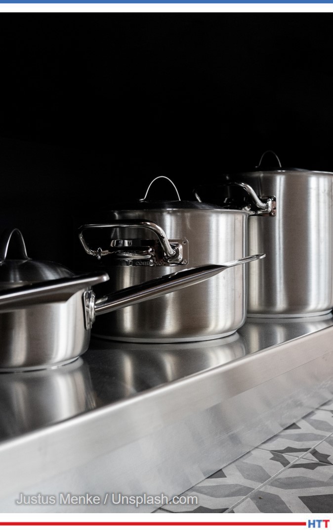
I did a study a few years ago: About 5–6% of the types of mesh belt furnaces in industry are actually this incline conveyor type.
Another good example is the fact that people like to run stainless steel cookware. I’ve seen pots, pans, sinks, etc. Sometimes you need a door opening of 20 or 24 inches high to allow a sink body to pass into it. Well, if that were a conventional, horizontal furnace, you’re limited to, perhaps, 9 to maybe, at most, 12 inches of height.
Typically you never want to go that high, if you can help it. 4–6 inches would be typical. So, there would be a tremendous safety hazard, among other things, to try to run a door opening that’s 24 inches high. But in an incline furnace, the height of the door can be 20, 24, 36 inches high. The chamber is at an 11° angle, and you must get up to the heat zone, but they run very safely at that.
Karen Gantzer: Could you explain what a retort is?
Dan Herring: Think of a retort — there are two types — but think of one as a sealed can, a can with a lid you can open, put parts in and then put the lid back on. The retort we saw in that box style furnace is that type. It is a sealed container. We typically call that a retort.
Now, in that pit furnace we saw, there could be a retort inside that one and they could be sealed containers, but typically they’re just open sides, that are made of alloy. Sometimes we call those “retorts” as opposed to “muffles” or “shrouds,” in another case. Muffles don’t have to be a sealed container, but they typically are. That’s the way to think of them.
Karen Gantzer: Thank you, Dan, I appreciate that.
Bethany Leone: Dan, thank you for joining us. It was really a valuable time.
We've assembled some of Heat TreatToday's resources on forging and metalcasting. Read or listen to what the experts have to say on these important topics in the heat treat industry.
This Technical Tuesday original content piece will help you wade into an introduction of these heat treatment processes. Follow the links to dive deeper into the studies.
The span of articles, radio episodes, and TV clips below are compiled to learn more about forging and casting. Heat treating is developing and changing through the years, and it's wise to keep swimming with the current of information.
Simulating Induction Heating for Forging
What can simulation software do for you? Manufacturers are able to run the software to act upon the steel billet prior to forging. Read more about the process here. The simulation shows results in the metal to help the user best plan for desired results. One of the decisions that can be helped is, "the selection of right forging temperatures for plain carbon and alloy steels to avoid possible damage by incipient melting or overheating."
A Look at Steel and Iron
Dan Herring "The Heat Treat Doctor" The HERRING GROUP, Inc.
Read or listen to this episode of Heat TreatRadio with expert Dan Herring who discusses metals such as stainless steel, tool steel, cast iron, high and low carbon steels, and more. He looks at their production and their uses.
"I wanted to set the stage for it to say that it’s the end-use application by the customer that fuels the type of steel being produced and fuels the form in which the steel is produced," says Herring.
Investment Casting in Turbine Blades
Take a look at how an alumina and silica (quartz) mix are improving metal casting for support rods used in aerospace manufacturing. "LEMA™, a range of proprietary alumina-based materials that provide double the mechanical strength of quartz while providing significantly improved leaching times, compared with typical high purity alumina," provides many benefits for metal casting. Jump into this piece to find out more about this metal casting example.
Direct From the Forge Intensive Quenching
President Akron Steel Treating Co & Integrated Heat Treating Solutions, LLC
In this discussion, expert Joe Powell says, "My thing is to develop a robust process that can be applied and implemented using automation and new equipment with the proper pumps and material handling that is all integrated into a seamless process." He plunges in to talking about immediate quenching pieces in water after heat treating and what they are learning at the forge shop.
Heat TreatTV
Here are a few episodes to keep you afloat while moving into deeper waters.
Click on these two illustrations to watch the full episodes.
Today's episode delves into the term "austempering". What is it? Why do heat treaters need to use it? For what applications is it necessary? Join Doug Glenn, publisher of Heat Treat Today and host of this podcast, as he talks with "The Heat Treat Doctor", Dan Herring, about all things austempering.
Below, you can watch the video, listen to the podcast by clicking on the audio play button, or read an edited transcript.
The following transcript has been edited for your reading enjoyment.
Earlier Episode of Lunch & Learn
Doug Glenn (DG): Alright, welcome everyone. We’re here with another Lunch & Learn with Dan Herring. Today, we’re going to be talking about the principles of austempering. We do these Lunch & Learns really for the benefit of our Heat TreatToday team and we knew that learning from Dan would also be educational for the entire industry. We are just really happy to be able to have Dan Herring with us once again to educate us a bit. We’re going to try to spend about 30 minutes or so learning about some of the very basic principles of austempering. So, the ball is over the fence to you, Dan.
Dan Herring (DH): Well, welcome everyone. It’s my pleasure to discuss the heat treat topic that we call austempering. One of the things we’re going to do today is we’re going to recall from a previous Lunch & Learn the definition of heat treating. We called it the controlled application of time, temperature, and atmosphere to produce a predictable change in the internal structure of what metallurgists call the microstructure of a material. So, we’re going to introduce various words that are related to different types of microstructures today or these internal structures.
But before we do, I’ve put on the screen a brief definition of austempering. It’s certainly a heat treat process. It’s used in medium to high carbon, both plain and alloy steels, as well as cast irons (an example being ductile iron) and we’re trying to produce a microstructure called bainite which is probably a foreign word to most of you and I’ll endeavor to explain it in a moment.
But to give you just a view from about 30,000-feet, you might be asking yourself, “Well, what types of products are austempered and why?” So, I put a couple of examples here. I’ve put an example of a lawnmower blade, seat belt components like the tongue and receptacle, and some tractor parts, as well.
A good example of this might be the seatbelt components. We’ve learned to put on seatbelts (in my day, we didn’t have them, but now we do) and we all learned to buckle up. And, if you get into an accident, you discover why your seatbelt is really your friend. We want something that’s strong, that if we get into an accident, it will not shatter and break. But, at the same time, we want something that’s tough and slightly ductile so it will bend and not break.
Austempering is a process that’s used to produce all seatbelt components, that I’m aware of. Similarly, with lawnmower blades- we don’t want a blade, if it hits a rock as we’re mowing the lawn, (I don’t expect most of the people on the call to have mowed the lawn), but if we hit a rock or a hard object as we’re mowing the lawn, we might want that lawnmower blade to get a ding in it, but we don’t want it to shatter. So, those are some typical examples.
You might ask yourself, why do you austemper? What we’re seeing here is that if you need increased ductility, toughness, and strength at a given hardness level, austempering is right for you. We’re typically talking about parts that are in the range of, maybe, 35-55 Rockwell C. We are developing, as I said, a bainitic structure as opposed to a martensitic structure, which is what’s produced when we harden a steel and quench into something like oil or water.
So, we get improved toughness. And we get some superior properties related to that, as well. And some of the properties don’t change very much but they’re equal to what we get when we harden the steel, when we get this martensitic structure.
The bottom line is we typically get less distortion, we get better wear resistance, we don’t suffer from cracking as some of the high carbon steels are prone to do, and, interestingly enough, with cast irons, we get some, what are called "improved dampening characteristics" -- noise and vibration. So, wire is an important like, for example, in an automotive engine to have dampening characteristics because we want the engine to run quietly.
What types of materials can be austempered? This is just a partial list, but mostly it’s medium carbon steels. That’s carbon steels with anywhere from .5 carbon to .95 carbon or, in other words, an AISI 1050 to 1095 grade. We can also do medium alloy steels -- the 4130’s, the 4140’s, the 5140’s, the 5160’s, etc. Certain stainless steels can be austempered although not many of them. And, as I said, cast irons, the example being ductile iron, can also be austempered.
And I wanted to give you some idea of the mechanical and different properties of steel. We talked in an earlier Lunch & Learn about the fact that steel is an alloy of iron and carbon and manganese. And we add other elements to the mix in order to get various either mechanical properties, chemical properties, electrical or magnetic properties, and certain other advantages.
So, an example of mechanical properties that we’re typically interested in is hardness and strength, brittleness, ductility, elongation, wear, and shock resistance. Now, strength is measured a number of ways. There are things called "fatigue strength" and "flexure" and "impact strength" and "sheer strength" and "tensile strength" and "torsion strength" and "yield strength."
This is a metallurgist’s rendition of a teeter totter in a schoolyard. Now, don’t laugh. This is what defines the difference between a metallurgist and a mechanical engineer. For all the mechanical engineers out there, metallurgists draw cartoons -- that’s the easiest way to say it. Howsoever, at one point in all of our lives, we’ve probably been on a teeter totter. We know that, in this particular teeter totter, we have strength properties on one side of the teeter totter and ductility properties on the other. We know that as the strength goes up, the ductility will go down and as the ductility will go up, the strength will go down. As a result of this, we decide what we want for properties and we realize that there’s a compromise going on. If we make them extremely strong, they’ll be brittle because they’ll have very, very low ductility. If we make them extremely ductile, they’ll have very low strength. So, this balancing act is what we’re trying to do when we look at the properties we’re trying to achieve. And, if you remember, the microstructure is what gives us these properties.
Now, this is something that is not intended to confuse, but I thought I’d add a little metallurgy into the mix because we are going to talk about several microstructures. This is what metallurgists call a "time temperature transformation" or "TTT diagram." This is really an artist’s rendition of one. There is a lot more information typically contained in one of these diagrams. But for our purposes, it isn’t too important. We can use this artist’s rendition to get the essence of what we’re trying to do.
We start off by heating steel to austenitizing temperature. And that’s above the dotted line shown in this particular diagram, so, at the very top of those turquoise lines and temperature. And then what we do is we make sure that the component part is uniformly up to temperature and now we get ready to harden it. We get ready to quench it. What we’re dealing with is we’re rapidly cooling, and under normal hardening, you’ll notice that there are two lines there- one called MS and one called MF. MS is the martensite start line and MF is the martensite finish line.
Typically, in hardening, our goal is to produce martensite. In order to do so, we want to cool rapidly enough to miss what we call "the nose of the curve" because if you look at this type of diagram, you’ll see that it, on profile, looks like somebody’s nose and the turquoise lines are missing the "nose" of the curve. As a result of that, we’re cooling rapidly. But the difference between hardening and austempering is that we don’t cross the MS point, we don’t cross into the martensite range. We don’t transform to martensite, instead what we do is we put the brakes on, we stop, and then we introduce a long soak or hold period and we cross into the banitic range of the curve.
And, so, austempering is typically performed about 25-50 degrees Fahrenheit above the martensite start temperature of steel. Now, there are some exceptions, but that’s a very typical range. If we’re not controlling the process properly, we might get a microstructure that’s both bainite and martensite. But if we do our job right, we’ll get a fully bainitic structure, which is often what we desire.
Read More in Dan Herring's Books
Now (and I realize this has words that some people may be unfamiliar with) but we’ve heated the part up until we’re austenitic- we’re in the austenite range, and there are three various methods of cooling that can be employed. On the far righthand side, if we rapidly quench a part into oil or into water, we might produce a microstructure that’s called martensite. It’s a body-centered tetragonal microstructure. We get something that’s very hard, but brittle. That’s why we have to reheat it and perform a process called ‘tempering’ in order to take some of the brittleness away and add some ductility back in.
Now, on the far lefthand side, we may slow cool the part rather than rapidly quench it and we produce a microstructure that is both ferrite and pearlite, the result of slow cooling. So, instead of getting something that’s very hard, we get something that is very soft. You might say, “My gosh, why do we want to do that?” Well, we like to do that sometimes because we like to take a steel and, for example, machine it into a final form before we go back in and reharden it. So, as a result of that, we form a ferrite/pearlite microstructure, we’re able to machine the part, then we can go back in and reharden it.
So, slow cooling gives us a ferrite/pearlite microstructure, rapid quenching gives us a martensitic microstructure, and a moderate cooling rate (the one shown in the center) gives us a bainitic microstructure. Bainite is a mixture of ferrite and cementite. Again, words that you’re perhaps not familiar with. But the way I like to say it is martensite gives us a microstructure that is not as hard as martensite but tougher, in general, than martensite, and we’ll explain that as we move forward.
But I thought before we do, you might want to see some typical type of heat-treating equipment that is used to austemper parts. A lot of parts are done in a mesh belt conveyer line. The one that is shown on the left, where parts are loaded onto a table, sent through the furnace, and dropped at the end of the furnace into a salt quench which is located in the floor, in this particular drawing. Salt is the primary medium that we quench parts that will be austempered in because salt gives us the temperature-range we need to be above the martensite start point.
Now, a number of people have asked me in the past: Can I use oil rather than molten salt to perform this operation? There are certain oils that can be used at extremely high temperature, but there are fire hazards and other hazards associated with them so the typical answer is ‘no’; molten salt is typically used to perform the quenching.
So, you have a mesh belt conveyer system for high volume, shown on the left. On the right, you’re showing a typical Shaker Hearth furnace where what happens is you load parts onto a pan that vibrates and the parts are moved down the length of the furnace and then drop into a salt quench at the back end.
I thought you might want to see some pictures of some stampings and things that are going into one of these mesh belt conveyer furnaces. You see the endothermic gas in this particular picture burning out the front of the furnace and the stampings moving on a conveyor belt, a mesh belt, in through the furnace. All sorts of different types, shapes, and sizes of stampings. One thing you’ll notice is that these parts are, typically, not single layer loaded; they’re loaded, perhaps, one to three to five parts thick, somewhere between anywhere from a half inch to about two or three inches thick as they’re moving through this conveyor belt.
And to complete the metallurgy aspect of it, you might say, “Hey, what type of microstructure am I actually seeing?” The picture on the left is a primarily bainitic microstructure with some martensite and its hardness is 44 Rockwell C. The microstructure on the righthand side is a combination of bainite and ferrite. The ferrite in this microstructure shows up as white or very light in color, exactly. This hardness, because you have ferrite present, is about 36 HRC. So, depending on the hardness you’re trying to achieve, you will get different types of microstructures- that’s the purpose of this slide.
Now, as far as molten salt goes, a typical austempering bath consists of either a sodium nitrate or a potassium nitrate salt, typically in a 50/50 mixture, and this salt is operating somewhere between 300 degrees Fahrenheit and 650 degrees Fahrenheit, depending on, again, the desired, not only the composition in the salt, but the desired temperature that we would want to hold to.
Let me back up for a second, Doug. So, to kind of summarize this: What we’re trying to put the brakes on as we’re rapidly cooling down, missing the nose of the transformation curve, we want to fall into this bainitic region and, in order to do so, we need to stay above that martensite start temperature which for many steels is in the 400–450-degree Fahrenheit range. So, our molten salts will typically run at 475, 500, even 550 degrees, all the way up to 650 degrees. So, we pick our salt temperature, not only depending on the salt, but also depending on the temperature that we want to hold the bath in.
Some of the reasons for selecting a salt quench are that the temperature of the salt bath dictates the ultimate hardness that we’re going to achieve. You might find this interesting: If I didn’t mention it in a previous Lunch & Learn, but I did, it’s that when we quench into the martensite range or field, martensite is the instantaneous sheer transformation. It really progresses at the speed of sound. So, martensite forms almost instantaneously, but bainite requires time for the transformation to take place.
So, a typical time in the salt is somewhere in the range of 18-20 minutes. I’ve seen parts held in salt for as short as 10 or 12 minutes and for as long as 30 minutes, but it depends on the thickness of the part, the material and, ultimately, the desired hardness we are going to reach. Now, interestingly enough, as opposed to a part that we harden to martensite and have to retemper or temper to balance the teeter totter, so to speak, with an austempering process, we do not need to temper afterwork because the parts are effectively tempered, so to speak, in the salt. So, we have a hardening operation that results in a banitic structure but we don’t need to temper. So, that’s one of the differences between hardening and austempering.
Again, the time in the salt will decrease as the transformation temperature increases and the time in the salt is similarly associated with the carbon content in the steel.
Let me give you a couple of examples: I mentioned in an earlier slide that SAE 1050, 1055, 1075 steel are typical steels that are austempered. Again, your austempering goes to put the hardness typically in the range of 40-45 Rockwell C, not nearly as hard as if we harden and quench them into oil or water, but certainly hard enough to give you a properly austempered part, giving you this part that is a combination of good hardness and yet a lot of ductility.
This, in a nutshell, is a brief summary of austempering. We’ve kind of said what it is -- it’s a process that’s going to get us a bainitic microstructure. We’ve looked at a little of the metallurgy of what we’re dealing with here and we’ve seen that it’s a different type of microstructure than is something like annealing or normalizing which gives you a primarily ferritic and pearlitic microstructure. And it’s different than hardening that gives you primarily a martensitic or tempered martensitic structure.
So, for those parts that require not only hardness but toughness, austempering is a process that should be considered by heat treaters.
Doug, that’s really the end of the presentation that I’ve prepared. We can certainly discuss it a little bit more if anyone has any questions.
DG: At the beginning, you were talking about pearlite and all that stuff, did we talk about austenite?
DH: Well, we talked about austenite because, again, that’s the temperature to which we heat the parts up to at the very beginning. In other words, to start the process, we heat the parts up to the austenite field, if you will. In other words, the parts are essentially red hot. They are above the proper transformation point that they turn into austenite.
DG: So, I assume that’s here, if you guys can still see the images: That’s austenite. The austenitic temperature is up above this dash line, right?
DH: That’s correct.
DG: And as you bring it down, you come through, perhaps, other, there’s a lot of different "ites" in heat treating, right? There’s austenite, pearlite, ferrite, bainite, martensite, you know, it sounds like a stalagmite and whatever those other things are in the caves, but all of those things basically are telling us about the orientation of the molecules inside the metal.
DH: Well, think of it this way, Doug: When we have a steel, its microstructure, if it isn’t hardened, its microstructure is typically body-centered cubic, which means the atoms are all lined up in a certain structure. Now, what we do when we heat it up is -- when it gets above the transformation temperature (that dotted line, for simplicity, in this example) the atoms will realign themselves from body-centered cubic to face-centered cubic and a face-centered cubic structure is called austenite. Then, when we quench it, until we move into the nose of the curve or past those red lines, we still maintain an austenitic crystal structure as we’re cooling. The ferrite, the pearlite and things occur when we cross over into those reddish lines in that area there.
I think you can do this- if we start off as austenite, and we slow, slow cool.
Slow, slow cool. We go all the way down like that. Keep going down, down, down, down, down. Okay, if we do something like that, (and I’ve got some pictures to show it better), but the idea being the fact that because we’ve fallen into the nose of the curve, we form a microstructure that is typically ferrite and pearlite. The first line you’ve drawn is indicative of an annealing process where we’re slow cooling inside the furnace. The second line you’ve drawn is more indicative of a normalizing process where we’ve cooled at a faster rate but still, in this case, we’ve fallen into the nose of the curve because it’s not that quick.
And to give everyone a perspective of the time element involved here, and I haven’t shown numbers, but the time element is for plain carbon steels, you may only have a few seconds to reach the nose of the curve. So, as a result of that, you have to move very rapidly where those turquoise lines are shown; you’re cooling at a very, very, very rapid rate to try to miss the nose of that transformation curve.
The secret with austempering is that you have to put the brakes on before you form martensite, and that’s not as easy as you might think it is. But that’s one of the reasons why molten salt is an excellent medium to quench into.
Don’t mix up crystal structures with microstructures. The ferrite, the pearlite, the bainite, the martensite are microstructures whereas the crystallographic structures -- body-centered cubic, face-centered cubic, body-centered tetragonal- represent how the atoms realign themselves.
DG: Does anybody have questions for Dan?
Bethany Leone (BL): I was thinking about asking you, Dan, but you have already essentially answered it: How difficult is it to have that rapid cooling and then control it to remain quite stable for a long period of time? You hit on the first part of the question which is the salt quench does a good job in this instance. But how does a heat treater maintain that stability of temperature for such a long time?
DH: That’s a great question because one of the interesting properties of salt, molten salt, is the fact that it is a bath that’s extremely uniform in temperature. So, when, for example, the parts, the stampings, and other parts are conveyed through a furnace, they then drop off into a quench and there is a conveyer belt in the quench, under the salt, that the parts drop on to this conveyor belt and then move through the salt. So, if I want 20 minutes in the salt bath, I have to run the speed of the conveyor slow enough to allow that time to take place.
Now, not to confuse everyone, but there are other ways you can austemper: You can heat in molten salt and then quench in the molten salt. So, there is a molten salt you can actually preheat in molten salt, have a high heat in molten salt and then a quench in molten salt. A lot of people don’t use that for high volume production work, but they still use that.
But, yes, you need time in the salt for that transformation to fully take place.
DG: Any other questions?
Let me do a couple other things and, again, we can probably put this up on the screen, but we just recently, I believe, already released this -- the Heat Treat Radio interview we did with Bill Disler regarding salt quenching. That may be of interest to people who have an interest in what about salt quenching? You might want to reference that sometime so, feel free to look into that. You also can just search our website for "bainite" or "austempering" and you may come up with some additional articles.
So, that’s it. Dan, thank you very much. I appreciate it. Unless anybody else another question, I think we’ll sign off at this point.
What makes the North American heat treat industry of 2022 what it is? As with any industry, the heat treating world is made up of the people who now inhabit it and the people who paved the way for them. Let’s take a moment to think about the past and what we owe to the industry giants, those trailblazers who have guided so many. In that spirit, enjoy the life stories of these three Heat TreatLegendsfromHeat TreatToday'sSeptember 2022print edition. After all, the industry is only as good as the people in it.
To listen to the life stories onHeat TreatRadio, click the section headings below.
Lost patents, risking a million dollars, and unleashing an entrepreneurial spirit he didn’t know he had. These are just a few things that characterized Bill Jones’ life.
Contact us with your Reader Feedback!
“First, you want to do something that you’re happy doing . . . Then, you must be properly prepared for it. You must have enough education to go forward.” So says Bill Jones, CEO of Solar Atmospheres Group of Companies. A self-proclaimed “technocrat,” Bill remembers being interested in technology from an early age. Technology was the “something” Bill was happy doing.
Throughout Bill’s career, his love of technology often led his peers to complain, “You know, Bill, you’re always interested in technology, and you’re not interested in whether you’re making money or losing money.” The complainers may have been right about Bill’s interests, but they were wrong about how much his love of technology would hinder his ability to make money. Today, Bill and his wife Myrt are the sole owners of four successful, family-owned heat treat companies based in North America: Solar Atmospheres, Solar Manufacturing, Magnetic Specialties, and Vacuum Furnace Systems.
"There is nothing that beats hard work and dedication to what you are trying to do." - William Jones
How did Bill go from being simply a technocrat to the owner of multiple businesses? Bill’s answer: work ethic and education. There is no substitute for being willing to put in more than 40 hours a week and to dedicate yourself to your work. But, Bill says, education is also a must: “We, as practical people in the heat treat industry, tend to pooh-pooh education,” and “[the] basis of what we do comes from chemistry. Metallurgy grew out of chemistry. If you don’t have a decent educational background, then you don’t know the basis of where we came from because that’s the basis of where we’re going.”
Armed with his education and his work ethic, Bill began his journey into the world of technology by working with dew point analyzers. At the time, there was no way to continuously monitor dew point or moisture, and Bill’s first project was to produce a dew point analyzer that could measure one to two parts per million. From measuring dew point, Bill moved on to measuring temperature, and this was his introduction into the furnace industry. In 1963, Bill began a career at Abar, where he used his experience designing optical pyrometers to produce thermocouples that could be used at above 4000°F.
At Abar, Bill worked as the equivalent of a chief engineer on a project that he would later characterize as one of the greatest accomplishments of his life: designing a vacuum furnace with a horizontal ring hot zone. When the new furnace started up for the first time, Bill saw what a ring hot zone could do. Bill still remembers the experience: “When I tested that first round hot zone, I did it by myself at night in a plant where I was the only one there. We had a big sight glass in the front of the furnace, and I could see the entire hot zone, the heating element, the heat shield, the ring and so forth, and I was able to measure the temperature and it was [like] ‘WOW. This thing works!’”
True to his technocrat identity, Bill views this furnace as his greatest accomplishment, not the success of starting his own companies. Along with the development of this furnace, Bill helped to develop the graphite hot zone, which later replaced the metal hot zones at Abar. With graphite hot zones, riveting was unnecessary, and the elements could be bolted together with graphite screws and nuts. One of Bill’s greatest regrets in life was not patenting the horizontal ring furnace. “We should have,” Bill says, “but we didn’t know what we had, honestly, and then it got out into the fi eld anyway and we couldn’t patent it.”
Lost patents, however, did not get in Bill’s way. Bill is also proud of the car bottom furnaces built at Solar’s Hermitage location in Western Pennsylvania. Bill remembers the weekly design meetings and running the furnace for the first time. The car bottom furnace was designed to process heavy titanium coils, and Bill was so confident in his work that he insisted on running the furnace for the first time with a million dollars of titanium coils inside. A coworker, Bob Hill, said, “Bill, you’re not going to run the final product first. I think we should make a run with just some scrap steel that we have around.” Bill replied, “No, Bob. I am thoroughly convinced this furnace is going to work and work right.”
Today, Bill and his wife Myrt are the sole owners of three successful, family-owned companies based in North America: Solar Atmospheres, Solar Manufacturing, and Magnetic Specialties.
Bill’s confidence paid off ; the car bottom furnace worked correctly the first time.
Chronicling his experiences, Bill wrote The Golden Nugget: An Entrepreneur Speaks. Bill’s identity as an entrepreneur was a surprise to him. Bill credits Dr. George Bentley with inspiring his entrepreneurial spirit: “Bill, I want to tell you something,” Dr. Bentley said, “I have observed you over the years and I can tell you, you are never going to be happy until you run your own business.” At the time, Bill did not realize the wisdom of the advice, he did not see himself as an entrepreneur. But now, Bill realizes, “Until you’re sitting in the top chair and until you’re making the decisions of winning and losing, you don’t know what it’s all about.”
Entrepreneurship (no matter how unplanned), innovation, valuing education, worth ethic, and above all else, a love of technology all helped Bill Jones along the road to success. And the main motivation? “Well, it’s very simple: Money is not a driving factor in my life or in my wife’s life. Money is not it. You know, the old saying is, when you go to the grave, there’s not going to be a U-Haul behind you.”
What’s the job of a good doctor? First, do no harm. This mantra, combined with Dan Herring’s love of doing good by solving critical problems, made him what he is today: The Heat Treat Doctor®.
The Heat Treat Doctor® has worn many, many hats throughout his more than 50 years in the heat treating industry. He was a metallurgist, a corporate trainee, an international marketing worker, an applications engineer, a technical director, a research and development director, a product manager, a chief engineer, and finally: an entrepreneur, the owner of his own consultancy, The HERRING GROUP, Inc. In Dan’s own words: “You might say that I’ve been chief cook and bottle washer of the industry, if you will.” These various jobs, and the multitude of different responsibilities that went along with them, taught Dan everything he knows today, developed him into The Heat Treat Doctor®, and made him worthy of being a Heat TreatLegend.
Looking back on his success, Dan points first to his parents for helping him to become the best version of himself. Dan grew up with one parent that gave him a love of technology and equipment and with one parent that give him a love for language and writing. Dan’s father, a machinist, was a hands-on worker and “one of the most inventive people that I ever met.” Later, Dan combined the technical skills he learned from his father with his education as an undergraduate in engineering and a graduate student at the Illinois Institute of Technology.
Dan’s mother, a registered nurse, was “an English teacher in disguise.” She gave Dan a love of writing. For over 10 years, Dan authored a monthly column for Industrial Heating. Columns, however, are not the extent of Dan’s writing expertise. He has also authored: Vacuum Heat Treating, Volumes I & II, and Atmosphere Heat Treating, Volumes I & II. These four books are excellent resources for heat treaters, both novices and experienced industry professionals. Dan has written 10 books in total, six of which deal with the heat treating field. Dan is proud of these books because he can share what he knows with others forever, just as others passed knowledge to him.
“I think it’s interesting,” Dan says, “I have had the extremely good fortune of working for two or three people that actually fell in the genius category. These people were absolutely, positively of genius intellects and they worked within the heat treating industry.” During Dan’s time at Lindberg, he met Hobart Wentworth. Wentworth taught Dan the discipline of engineering, taking Dan’s university knowledge into the real world. Also at Lindberg, Dan was introduced to Russ Novy, chief metallurgist. Dan commends Novy for his “infinite patience . . . to tell you what he had learned and explain things and talk about the root cause of things.” When Dan worked at C.I. Hayes, he met Herb Western, a man who holds over 300 patents in the state of Rhode Island. Western showed Dan how to be creative and inventive within the heat treating industry.
Vacuum Heat Treating, Volumes I & II Atmosphere Heat Treating, Volumes I & II (For more information: www.heatreattoday.com/industryresources/books/herring-books)
One of Dan’s greatest accomplishments was establishing The Heat Treat Doctor® brand. “The brand,” Dan says, “has brought heat treating into the forefront of manufacturing, into the forefront of the industry, into the forefront of engineering, that yes, there is something called heat treating and it is a solution to your needs. So, I view the brand as not so much a personal accomplishment but as an industry accomplishment.”
Dan’s love of words gives him a unique skill set. Not only does he understand metallurgy and engineering, but he is also patient enough to explain it and has the communication skills to explain it well.
When it comes to business, Dan’s main rule is: “Be honest . . . be ethical, be fair, try hard, communicate well and have infinite patience. In other words, not everyone understands what you’re saying. You must take the time to explain what you mean to the people you’re dealing with. Although that’s a strange answer on the business side, I think it’s most impactful.” Dan takes pride not only in doing good throughout the industry, but also, like a good doctor, doing as little harm as possible. Helping others with critical problems, getting companies back in operation, and preventing layoffs are events that stand out the most to Dan.
When it comes to life, Dan’s mantra is: Enjoy the moment. “I remember the first day I started to work at Lindberg,” Dan says, “I took the train to work, it was right across the street from the train station, I was walking across the street, I was 21 years old, and I said to myself, ‘Only 44 years to go.’ And I turn around and the 44 years have disappeared like it was yesterday. So, you must enjoy what you do, and you’ll never work a day in your life.”
Dan attributes his success in the industry to the people around him. He points not only to his parents for his success, but also to the “geniuses” he has worked with along the way, and to the industry at large. Speaking of his entry into Heat Treat Legend status, Dan says, “I just want to say that I consider this a distinct privilege to be considered one the Heat TreatLegends. But I’d also like to point out to everyone . . . that no one individual can do it by themselves. So, I’m accepting this accolade, if you will, on behalf of the many men and women who toiled in, what I’m going to call, relative obscurity and who made this industry what it is today. On their behalf, I’m more than willing to be considered one of the Heat TreatLegends.” Spoken like a true legend.
“Happy, happy, happy.” In Suresh Jhawar’s experience, the best way to run a business is to focus on happy employees, happy customers, and happy bottom lines.
What happens when a young man comes to the United States against his parents’ wishes to earn a bachelor’s degree in Engineering? He becomes the sole owner of G-M Enterprises and gets the title of Heat TreatLegend. At least, that is what happened for Suresh Jhawar, a self-proclaimed “average student in India.”
Without the support of his parents, Suresh weighed the odds of coming to America versus studying in Germany or the U.K. and applied for his visa and passport in a library, away from his parents. When Suresh discovered he could earn his degree in half the time with his advanced credit, he chose the United States and boarded a plane, arriving in the States in 1962. At Marquette University in Milwaukee, Suresh went on to earn a master’s degree in Mechanical Engineering and an MBA in Marketing.
Before taking ownership of G-M Enterprises, the two heat treating companies that were most influential for Suresh were Abar and Ipsen. Suresh began his time with Ipsen in 1970 as a project engineer for vacuum furnaces. Suresh was in the top five at Ipsen, and, looking back, he sees himself driving the company in cost savings, product improvement, and customer relationships.
As the assistant to the president at Ipsen, Suresh traveled extensively to Poland to visit a facility for steel milling and annealing silicon steel coils for transformer steel. During this time of heavy travelling both at Ipsen and later at Abar Furnaces — Suresh visited Poland ten times in less than two years — he remembers the difficulty of keeping a healthy work/life balance. But he succeeded most of the time: “[W]hen Andy [Suresh’s son] was getting an award at his high school, I was coming from Europe . . . I missed my connection. Now it became difficult as to how to get to Philadelphia to attend that awards ceremony for my son . . . I went from one airline to another. I got on a plane, reached Philadelphia airport at the time when the program started, but I was at the school at the right moment when Andy’s name was called. I was there!”
Difficult though it may have been, Suresh often succeeded in keeping work and life in balance. At Ipsen, work consisted of many projects, one of which involved helping Ipsen book an order for 10 large car bottom furnaces. While Ipsen’s president handled the commercial aspect of the order, Suresh handled the technical side of things. He had to make sure the company had the right product and the right solution. And the 10 car bottom furnaces — 84 inches wide by 45 inches high by 32 feet long, made in four bolted sections — were indeed the right solution.
“What I believe is ‘happy, happy, happy’: happy employee, happy customer, happy bottom line.” - Suresh Jhawar
It was at the same time as this project that Suresh was also working on Ipsen’s license agreement with Elterma, which later became SECO/WARWICK. Suresh’s work at Ipsen lasts to this day. Without Suresh, Ipsen would have no manufacturing base in India. Suresh enlisted Wessman Engineering as a sales agent for Ipsen, which began Ipsen’s history in India.
Abar was Suresh’s act two. Suresh wanted to run the entire operation, and Abar gave him the opportunity to do this. Under Suresh’s leadership, Abar increased its profit significantly, and Suresh was asked to write a justification for the merger between Ipsen and Abar. At G-M Enterprises, Suresh’s skills were on full display. Suresh entered G-M Enterprises as a partner holding 15% interest. Within a year, Suresh bought out one of the other partners, and later, in 2005, Suresh took full ownership of the company. He changed the official name of the company to Jhawar Industries and continued to do business as G-M Enterprises. When Suresh joined G-M Enterprises, it was a break-even company. By the time he retired, it was doing business all over the world. “I’m pretty sure,” Suresh says, “that we had the highest bottom line in the industry.” In 2005, Suresh hired his wife, Veena Jhawar, as the director of supply chain, enabling him to focus entirely on developing customers and innovating vacuum furnaces. Suresh’s innovation did not stop there as he was also instrumental in developing the MIM furnace. By 2018, G-M Enterprises was a leading supplier to GE from Singapore to Japan and Brazil.
How did he do it?
“What I believe is ‘happy, happy, happy’: happy employee, happy customer, happy bottom line.” When it comes to happy employees, Suresh says, “The most important thing is to treat your employees like you treat yourself. When I worked at G-M, out of any of the other places, I didn’t work as being ‘the boss’ or on a high platform; I worked shoulder to shoulder with them.” In order to be successful, Suresh believes you must respect your employees and reward them for their contribution, and hopefully, they will be loyal to the company.
Loyal employees make for happy customers. Happy customers, in Suresh’s thinking, have to feel they are a critical part of the solution. This was one of G-M Enterprises’ best qualities. If a customer had a problem, someone from G-M would jump on a plane and fix it, attending to the problem first and worrying about the terms later. Listening to what customers actually wanted, rather than simply giving them what the company already had, was a crucial part of building customer loyalty. With these two principles in place — happy employee and happy customer — the bottom line grew happier and happier.
With these two principles in place — happy employee and happy customer — the bottom line grew happier and happier.
Along the way to a happy bottom line, Suresh discovered the importance of meeting deadlines. Suresh remembers showing up to a production control meeting with no drawings in hand and the others in the room laughing at him. Suresh could tell they were thinking, “He puts pressure on us, but he doesn’t do his own job.” And so, Suresh never went home that day, but instead worked through the night. In the morning, he put all the drawings into the hands of the engineering crew. “Meeting deadlines and commitment, to me, is always number one. No excuses . . . That helps you to expect [the same] from other people, [because] when they see you — that you do that — they follow.”
Reminiscing, Suresh remarks, “We always treated our employees as family members and gave them due respect for their contribution.” For Suresh Jhawar, success in business is all about happiness.
Find heat treating products and services when you search on Heat TreatBuyers Guide.com
Heat Treat Radio host, Doug Glenn, and several otherHeat Treat Today team members sit down with long-time industry expert Dan Herring, The Heat Treat Doctor® of the HERRING GROUP, to finish the conversation about mill processes and production. Enjoy this third informative Lunch & Learn with Heat Treat Today.
Below, you can watch the video, listen to the podcast by clicking on the audio play button, or read an edited transcript.
The following transcript has been edited for your reading enjoyment.
Dan Herring (DH): When it comes to heat treating, the mill will do what we typically call ‘basic operations.’ They will anneal the material and, if you’ll recall, annealing is a softening operation (it does other things, but we will consider it, for the purpose of this discussion, a softening operation) so that the steel you order from the mill will be in a form that you can then manufacture a product from. You can machine it, you can drill it, you can bend it and things of this nature.
Contact us with your Reader Feedback!
There are various forms and various types of steel that can be ordered directly from the mill. So, the mill typically does annealing operations and normalizing operations. The difference between annealing and normalizing is that annealing has a slower cooling rate than normalizing does.
In the aluminum industry, we don’t talk about normalizing but talk about homogenizing. Homogenizing is to aluminum what normalizing is to steel; it’s a crude analogy, but it’s true. The mill can do other processes; they can do other heat treatments, they can do specialized rolling and things of this nature to give you enhanced mechanical properties. In today’s world, there is a lot of what we call “custom” or “specialty mills” that can manufacture very specialized products. There are mills that primarily make pipe and tube, there are mills that make primarily wire, there are mills that make primarily strip. There are some very customer-specialized mills out there. In general, a mill will produce most of the type of products that we see or use in industry (or the steel for those products), and they will make it in a form that is usable for the end user and heat treated to a condition where the end user can make a product with it. Now, obviously, once you make a product, you may then have to further heat treat that product, for example, to harden it or to give it certain characteristics that you need. We’ll talk about those things in later discussions about this.
What I did want to talk about is the types of steel that are produced by the mills. I’ll do this, hopefully, in a very, very broad context, but I think it will make sense to everybody. Again, metallurgists aren’t known too much for their creativity, so we start out with something called carbon steel. Very original. There is low carbon steel, medium carbon steel and high carbon steel. Low carbon steel has low carbon, medium carbon steel has medium carbon, and a high carbon steel has high carbon.
Now, to be more serious, a low carbon steel typically has less than or equal to 0.3% carbon, or less than 0.3% carbon. A medium carbon steel has between .3% carbon and .6% carbon, and a high carbon steel is greater than .6% carbon. An example of a medium carbon steel might be a 1050 or 1055 grade of steel. Those are commonly used for stampings, for example. So, all of your seatbelt, both the tongue and the receptacle are made of a 1050/1055 steel and they’re austempered to give them both strength and toughness so that in an accident, the buckle won’t shatter because it’s hard but brittle and it won’t bend abnormally and therefore release because it has inherent toughness.
So, there are various things you do with these carbon steels in the heat treat mill to enhance their properties. Carbon steels are used because they’re low cost and they’re produced in tremendous quantities. If you went to a hardware store and bought a piece of steel, it is very likely it will be a simple carbon steel.
On the other hand, we also make alloy steels and, interestingly enough, there are low alloy steels, medium alloy steels, and guess what, high alloy steels. Again, metallurgists are very creative with their names. But idea here is you get higher strength than a carbon steel, a little better wear resistance and toughness, you get a little better corrosion resistance, for example, you might even get some specialized electrical properties and things like this.
But low carbon steel, just to go back to that for a minute, as I said, is produced in huge quantities. Examples are steel for buildings, steel for bridges, steel for ships. We learned our lesson, by the way, with the Titanic; we got the steel right this time. The problem with that steel, by the way, was high in sulfur which embrittled it, interestingly enough, in cold water. So, when it hit the iceberg, the steel shattered because it was brittle because it had too much sulfur. But we learned our lesson.
Titanic, 1912 Source: Wikipedia
There are also various construction materials; anything from a wire that’s used in fencing to automotive bodies to storage tanks to different devices.
When you get into medium carbon steels, because they have a little better strength and a little better wear resistance, you can use them for forgings, you can use them for high strength castings. So, in other words, if you’re producing gears or axles or crank shafts, you might want to consider a medium carbon steel, or seatbelt components as we talked about.
Then there is the family of high carbon steels. Again, they can be heat treated to give you extremely high hardness and strength. Now, they’re obviously more expensive than medium carbon or low carbon steels, but when you’re making knives and cutlery components, (knives and scissors, for example), when you’re making springs, when you’re making tools and dyes. Railroad wheels are another example of something that might be made out of a high carbon steel. As a result of this, the type of product that your company is producing, means that you’re going to order a certain type of steel that you can use to make your product and give it the longevity or the life that your customers are expecting.
One of the things about steel that differentiates it from aluminum: Aluminum has a very good strength to weight ratio. But so again does steel, but obviously the strength to weight ratio, the weight is specifically much more, from that standpoint. But we can take steels that we produce from the mill, and we can do processes like quench and temper them. If we do that, we can make things like pressure vessels, we can make the bodies of submarines, for example, we can make various pressurized containers and things.
Stainless steel pots Source-Justus Menke at Unsplash.com
There are a lot of different things we can do with steels to enhance the products that we’re producing. Besides just low carbon steel or carbon steels and alloy steels, we then can go into the family of stainless steels, for example. Most people think of stainless steels as being corrosion resistant. I’ll warn you that not all stainless steels, however, are corrosion resistant; some of them can corrode in certain medias or chemicals, if you will. But with stainless steels, a good example of that is food processing containers or piping or things that will hold food or food products, and again, we can make with stainless steels a variety of different products. We can make different components for buildings, for example, or for trim components and things.
Besides stainless steels, of course, we can make tool steels. Now, tool steels represents a very, very high alloy steel. The alloying content of tool steels is typically 30 to maybe 50% alloying elements: molybdenum and vanadium and chromium and these types of materials. As a result, we can make a lot of dyes and we can make a lot of cutting tools, we can make taps and other devices that are used to machine other metals, if you will. So, tool steels have a lot of application.
But there are a lot of specialty steels that are made by the mills, as well. One example of that, that I like to talk about or think about, is spring steels because you can make various things like knives and scraper blades, putty knives, for example, besides cutlery knives. You can make reeds for musical instruments, the vibrating instruments in the orchestra, if you will. You can make springs and you can make tape measures, tapes and rules and things of this nature out of these various spring steels, if you will.
Depending on what your end-use application is, the bottom line here is that whatever your end-use application is, there is a particular type of steel that you should be using and there is a form of that steel that you can use. Again, those steels can be produced by a variety of different processes; they can be forged, they can be rolled, hot and cold rolled, again. And when I’m talking about hot rolling, I’m talking about temperatures in typically the 1800-degree Fahrenheit to 2200/2300-degree Fahrenheit range. When I talk about hot rolling, the metal is, indeed, hot, if you will.
By the way, roughly, iron will melt at around 2800 degrees Fahrenheit, just to give you a perspective on that, if you will.
The key to all this is that the form that is produced by the mill meets the needs of their customers and their customers’ applications. If you need a plate, for example, they will produce plate in various sizes and thicknesses.
Rolling direction Source: Barnshaws Group
By the way, just a quick note, and this is for all the heat treaters out there: Be careful of the rolling direction in which the plate was produced. We have found that if you stamp or cut component parts out of a plate with the rolling direction, or transverse or across the rolling direction, you can get vastly different properties out of the products. It’s amazing that you can get tremendous distortion differences from heat treated products depending on the rolling direction. If you’re stamping or forming out of a plate, you’re transverse or in line with the rolling direction. Most people don’t even think of that. They take the plate, they move it into the stamping machine, and they could care less about the rolling direction. Then, when the poor heat treater does his heat treating and distorts all the parts, the man comes back and says, “What’s wrong?”
By the way, that little example took only nine years of my life to solve. We had some, what are called, "springs" that are the backing on a knife. When you open a knife blade, there is a member that it’s attached to called a spring. Those springs were distorting horribly after being oil-quenched in an interval quench furnace. It happened to be a conversation around the coffee machine where one of the guys made the comment that, “You know, it’s really funny, we never had problems with distortion until we got that new stamping machine in.” Low and behold, in investigating it, the old machine took the plate in one direction, the new machine had to take the plate in a different direction and it rotated. . . . End result.
So, I guess for everybody listening, the key to this is that no matter what the material is that’s being produced, we need to use it sometimes in its cast form, we need to use it sometimes in its finished forms, which again can be bar and sheet and plate and wire and tube and things of this nature. And to get those shapes, we need to do things like hot and cold rolling, we need to do forging, we need to do operations like piercing to actually produce rings and things of this nature. So, although I didn’t go all the details about that, there is a lot of information out there about it. I wanted to set the stage for it to say that it’s the end-use application by the customer that fuels the type of steel being produced and fuels the form in which the steel is produced.
Perhaps as a last comment, on my end anyway, at this point, is the fact that a mill is a business just like anyone else’s business. We’re always looking for ways to cut costs, (not cut corners, but reduce cost), and mills have found that in the old days — and the old days weren’t necessarily the “good old days” — a mill made everything; they made all types of steel, they made all types of shapes and forms. But today, a lot of mills are saying it’s not economical to produce that particular type of steel or that particular form of steel, so we’ll leave that steel production to someone else, and we’ll only concentrate on high volume production.
You know, it’s very producing steel, a typical heated steel (and people will probably correct me on this), is somewhere in the order to 330,000 pounds of steel. So, if you’re a small manufacturer and don’t happen to need 330,000 pounds of steel, you have to go to a distributor and, more or less, maybe compromise a little bit to get the steel that you need. But the mills are producing large quantities of steel and very specialty steel grades, in general, today.
Doug Glenn (DG): It’s essentially specialization of labor so it helps keep each individual mill’s cost down, but it doesn’t have the variety it used to.
Let’s open up for questions, really quick. I’ve got one if nobody has one, but I hope somebody else has one. So, fire away if you’ve got one.
Carbon steel gate valve Source: Matmatch
Bethany Leone (BL): When you said that, Doug, my question jumped out of my head. I had 3 questions though but the ones I remember aren’t that important. One is — I recently visited an old blast furnace in Pittsburgh, Carrie Blast Furnaces; everybody should go, if you’re in the Pittsburgh area), so some of this sounds familiar. The second thing I was wondering is just how high can the carbon percentages go in carbon steels, .6%+, right?
DH: Yes, greater than .6%, and it’s not uncommon for carbon in various types of steels to go over 1%. It typically can go in certain tool steels and things higher than that. But one of the things that differentiates a steel from a cast iron is the percentage of carbon in the material. And carbon over 2% is considered a cast iron as opposed to a steel. Steel has a carbon percentage from .008 all the way up to 2%. That’s a great question and something to be aware of. When you buy a cast iron skillet, for example, you’re getting a material that has greater than 2% carbon in it.
BL: The other question I had is sort of more on the business end, if you know any of this, is- with the high energy that it takes to process iron, I imagine there have been efforts to try to reduce costs to produce energy that’s used to be a technology and innovation and especially right now with many people concerned with sustainability in those practices, are there ways that maybe even clients have influenced how businesses iron manufacturers in the iron manufacturing world have been trying to keep those environmental loads down, do you know?
DH: That’s a very intriguing question. I don’t have all the facts and information on it, but I’ll share a few things. As opposed to the production of aluminum, which is primarily using electricity, steel production uses typically natural gas. There were, in the old days, oil-fired equipment and things of this nature but today it’s typically gas-fired furnaces and things of this nature. Now, I have to be careful when I say that because some of the steel refining methods, (for example, the vacuum arc remelting furnaces and things of this nature), again, use carbon electrodes and use electricity, if you will, in the process. But essentially, what they’re trying to do is they’re trying to, for example, capture waste heat and reuse it to preheat different materials and processes and things of this nature, and they’re using methods that are trying to make the overall equipment more energy-friendly; if you will, better insulations, better fit of components than the old days when they didn’t care too much about if we got heat pouring out into the shop, we don’t care. Today, we really care about those things.
But steelmaking, again — for a different reason than aluminum — is a very energy intensive process; it uses a lot of energy to produce steel.
I’ll make a quick comment also, and I’m not saying this especially from anyone internationally who happens to be listening in to this: I’m not saying this is an “America only” comment, if you will, but in 1900, the largest industry, the largest company in the U.S. was U.S. Steel. United States Steel was the number one most profitable company in the country. If you think about it, throughout what would be the 20th century, steel and steel production has fueled, if you will, the American economy. We’ve since transitioned to other more angelic materials, if I can use that phrase; I won’t define it. However, who do you think produces over 50% of the world’s steel today? Anyone want to guess?
DG: The U.S.?
DH: No! China. And where is the manufacturing growth taking place? So, the production of aluminum, the production of steel, fuels manufacturing is my message here.
Yes, there are environmental consequences, but I often use the phrase and, again, this is not intended to be insultive to any one country, but for all the recycling, for all the energy saving, for all the environmental progress we can make in the United States, if we could reduce coal consumption in China (and India, of course), it would have major, major impact on the environment. And that’s not having 100-year-old steel mills, like we have here in the U.S., will go a long way, if you will.
DG: I’m going to give you 30 seconds, Dan, to answer one more question, okay? Here’s the question: Aluminum doesn’t rust, most steels do. Why is that?
DH: In simple terms, because aluminum reforms an aluminum oxide on the surface and that oxide is impenetrable, virtually, to further oxidation, whereas iron produces an iron oxide on the surface in the form of rust, it flakes off and you can reoxidize the surface. Now, there are steels — core10 is an example — self-rusting steels, that once they rust, they don’t reoxidize, but that’s the basic difference, Doug, between them.
DG: Perfect, perfect.
Alright guys. Thank you very much, Dan. I appreciate it. We’re going to get you on deck for another one here pretty soon on another topic, but we appreciate your expertise.
DH: Always a pleasure and, as I’ve said, I’ve reduced 3,000 pages into 30 minutes so hopefully people that are interested will read up more on these processes.


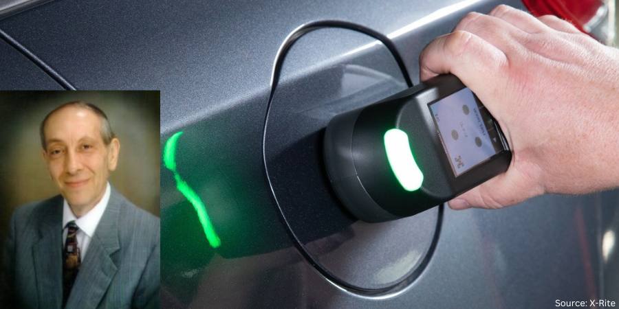


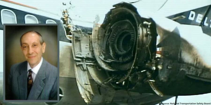

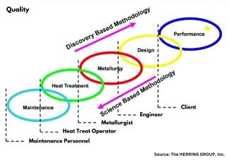
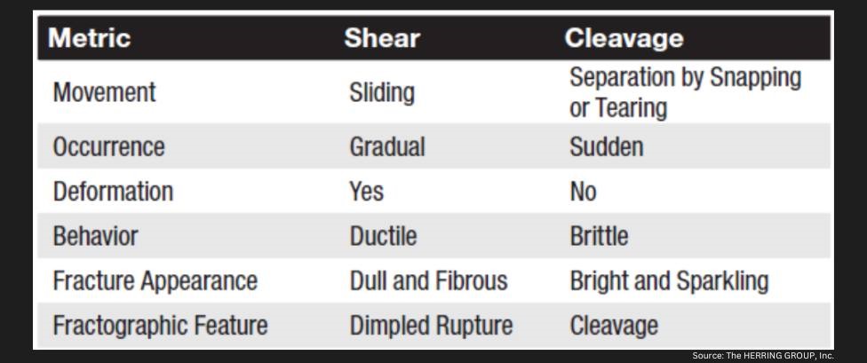

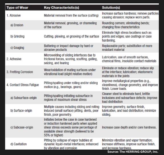
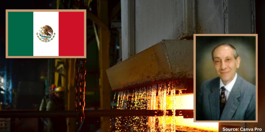
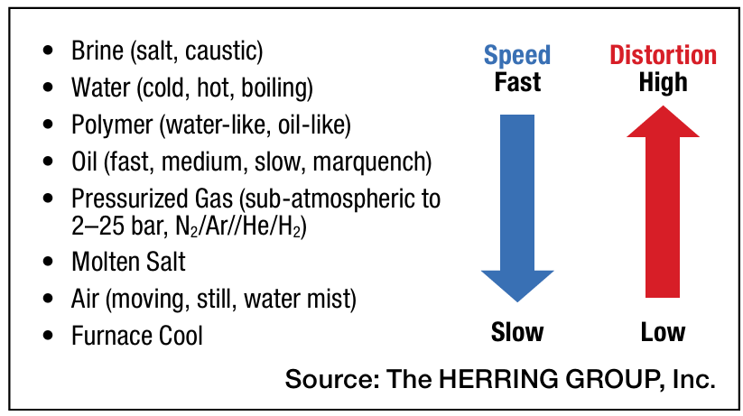


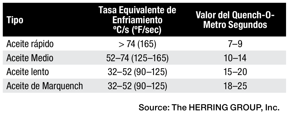


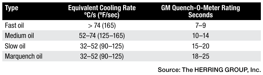


 Are you trying to figure out what heat treat equipment investments you need to make in-house and what is better being outsourced? This conversation marks the continuation of Lunch & Learn, a
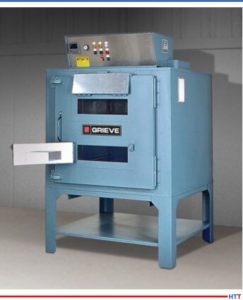
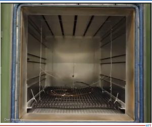
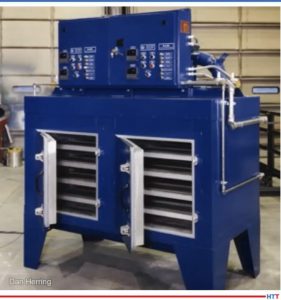
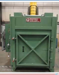
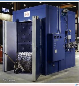
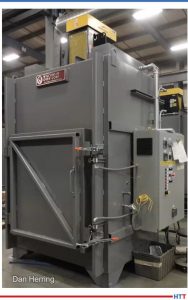
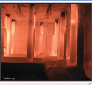

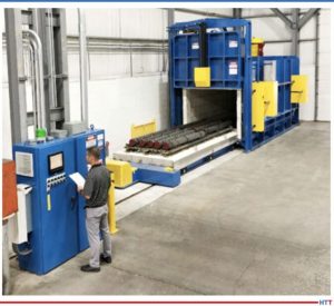
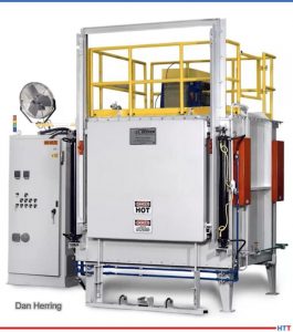
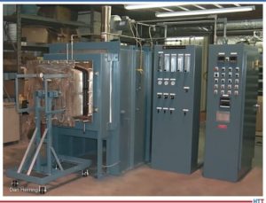
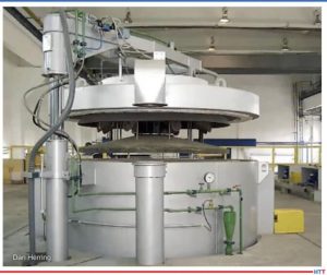
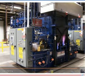
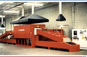

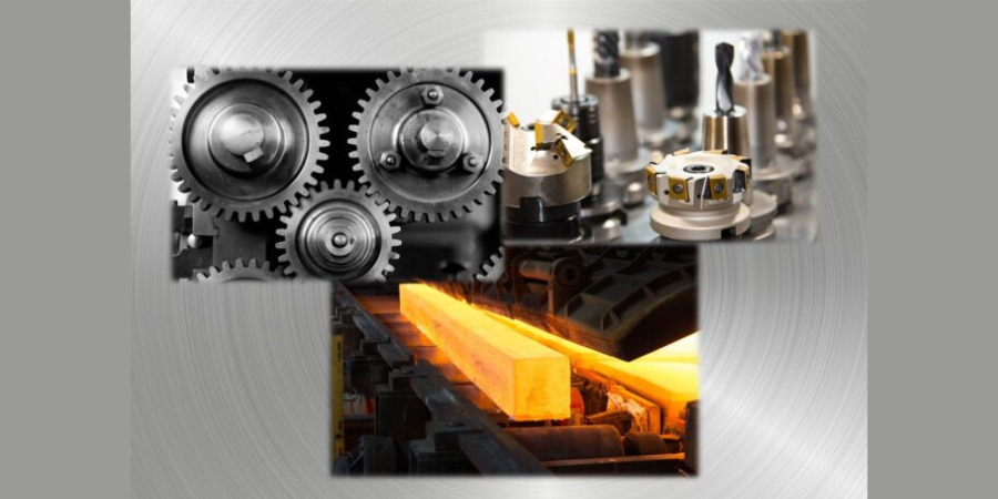


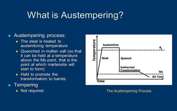 But before we do, I’ve put on the screen a brief definition of austempering. It’s certainly a heat treat process. It’s used in medium to high carbon, both plain and alloy steels, as well as cast irons (an example being ductile iron) and we’re trying to produce a microstructure called bainite which is probably a foreign word to most of you and I’ll endeavor to explain it in a moment.
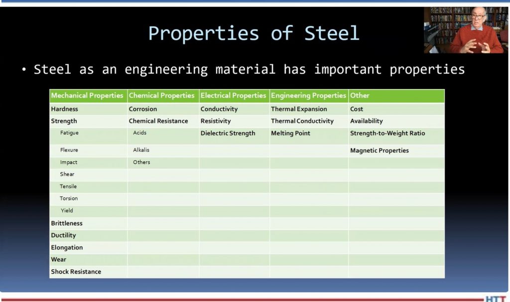
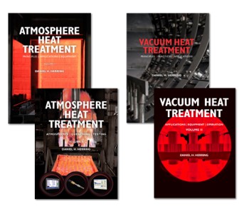
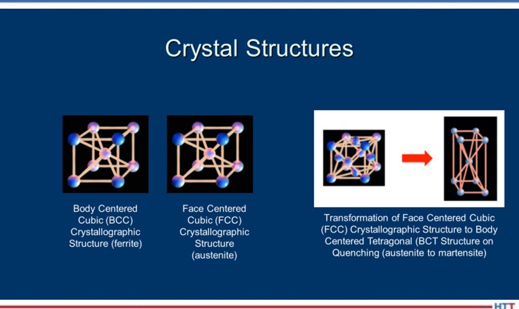 DH: Well, think of it this way, Doug: When we have a steel, its microstructure, if it isn’t hardened, its microstructure is typically body-centered cubic, which means the atoms are all lined up in a certain structure. Now, what we do when we heat it up is -- when it gets above the transformation temperature (that dotted line, for simplicity, in this example) the atoms will realign themselves from body-centered cubic to face-centered cubic and a face-centered cubic structure is called austenite. Then, when we quench it, until we move into the nose of the curve or past those red lines, we still maintain an austenitic crystal structure as we’re cooling. The ferrite, the pearlite and things occur when we cross over into those reddish lines in that area there.