


Dan Herring

Ask The Heat Treat Doctor®: Hot Topic for a Cold Day — Why Is Hot Gaseous Corrosion So Devastating?

Ask The Heat Treat Doctor® has returned to bring sage advice to Heat Treat Today readers, answer questions about heat treating, brazing, sintering, and other types of thermal treatments, as well as metallurgy, equipment, and process-related issues. In this installment, Dan Herring examines the devastating effects of hot gaseous corrosion on furnace alloys: exploring the mechanisms behind metal dusting, the gas-solid reactions that drive catastrophic carburization, and the mitigation strategies to extend the life of heat treaters’ most valuable furnace components.

This informative piece was first released in Heat Treat Today’s January 2026 Annual Technologies To Watch print edition.

Have questions or feedback? We’d love to hear from you — reach out to our editorial team at editor@heattreattoday.com.


Corrosion is a concern experienced by everyone involved in manufacturing industrial products. While there is a plethora of data and information on the effects of corrosion on engineered materials available (sources provided in the references section of this column), most corrosion engineers are focused on aqueous corrosion. By contrast, heat treaters must understand the effects of hot gaseous corrosion, especially on our furnace alloys. Let’s learn more.

Corrosion Basics

It is important to understand that all materials are chemically unstable in some environments and corrosive attack will always occur. In the scientific world, it can often be modeled and its effects predicted by studying thermodynamic data and knowing which of the many corrosion-related chemical states are active. In our world, however, it is equally important to understand the various forms of corrosion, namely:

  • Dezincification (aka selective leaching)
  • Electrolytic
  • Erosion
  • Galvanic (or two metal) action
  • General (aka uniform) attack
  • Intergranular attack
  • Pitting
  • Stress corrosion

The greater the metal’s solubility, the greater the degree and severity of the corrosive attack. There are many important variations of these forms of corrosion; two of the most important are 1) localized corrosive attack (e.g. pits, intergranular attack, crevices) and 2) interaction with mechanical influences (e.g., stress, fatigue, fretting). These actions are frequently rapid and have catastrophic effects.

The number of ways to combat corrosion have been well-documented, including alloying to produce better corrosion resistance materials; cathodic protection (via sacrificial anodes); coatings (metallic or inorganic); organic coatings (e.g. paints); metal purification; alteration of the environment; and nonmetallic or design (i.e., physical) changes.

Heat Resistant Alloys

Furnace interiors contain numerous examples of heat-resistant nickel-chromium-iron (Ni-Cr-Fe) alloys, including radiant tubes, fans, heating elements, roller rails and rollers, thermocouple protection tubes, chain guides, and atmosphere inlet tubes, to name a few. Baskets, grids, and fixtures are other examples. These alloys are normally selected based on their strength (at temperature) rather than resistance to corrosive attack.

Since these heat-resistant alloy parts are often the most expensive furnace components, heat treaters must understand how they can be attacked and what can be done to extend their life by minimizing or preventing corrosion.

Gas-Solid Reactions

A chemical reaction involving a (non-equilibrium) gas or gas mixture and a solid is classified as a gas-solid reaction. Examples of intermediate and high temperature reactions of this type include oxidation, sulfidation, carburization, and nitriding. Effects of gases containing vapors of chlorine, fluorine, and effluents from deposits of various alkaline chemicals (from cleaning compounds) and even phosphates are also problematic. The principles are the same for all types — only the details differ. As heat treaters, our interest is in controlling, retarding, or suppressing these reactions to prevent unwanted corrosion, gasification, or embrittlement of the furnace alloy or materials being processed.

Examples of Catastrophic Carburization (a.k.a. Metal Dusting)
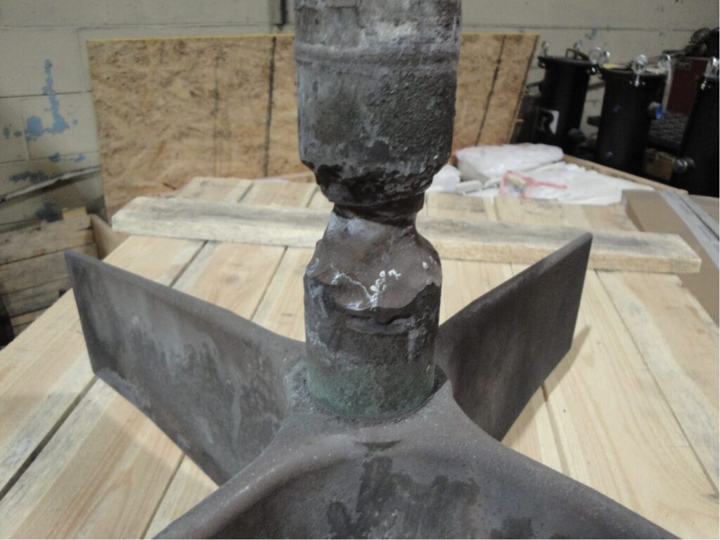
Figure 1. Pusher furnace alloy fan and shaft assembly | Image Credit: The Heat Treat Doctor®

Metal dusting (Figure 1) is a hot gaseous corrosion phenomenon in which a metallic component disintegrates into a dust of fine metal and metal oxide particles mixed with carbon.

Generally, metal dusting occurs in a localized area, and how rapidly the disintegration progresses is a function of temperature, the composition of the atmosphere and its carbon potential, and the material. Other significant factors include the geometry of the system, reaction kinetics, diffusivities of alloy components, the specific-volume ratio of new and old phases, and the ultimate plastic strain.

Metal dusting usually manifests itself as pits or grooves on the surface, or as an overall surface attack in which the metal can literally be eaten away in a matter of days, weeks, or months. As an example, this writer has seen a 330-alloy plate mounted underneath a refractory-lined inner door of an integral quench furnace (where atmosphere passes underneath the door and into the quench vestibule) reduced in thickness from 12.5 mm (0.50 in) to less than 0.75 mm (0.03 in) in a little over two months.

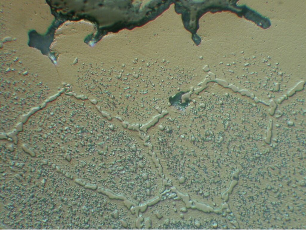
Figure 2. 330 alloy radiant tube removed after six months of use (rotary retort furnace) | Image Credit: The Heat Treat Doctor®
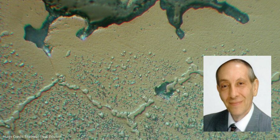
Figure 3. Microstructural view: catastrophic carburization | Image Credit: The Heat Treat Doctor®

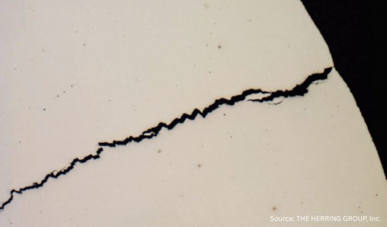
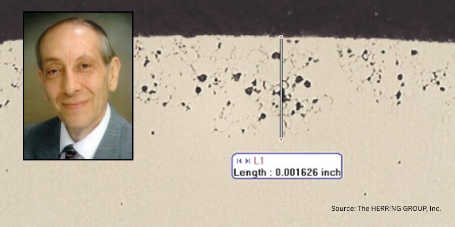
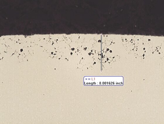
In another example, a metallographic investigation performed by this writer on a failed wrought 330 alloy radiant tube (Figure 2) was conducted. Optical microscopy of the inside (Figure 3) and outside diameter surfaces in the attacked area revealed evidence of massive carbides. These carbides are formed by the reaction of carbon with chromium, depleting the matrix of chromium in regions adjacent to the carbides. Grain detachment and subsequent failure by erosion then occurred.

How Does It Occur?

In general, catastrophic carburization of ferrous alloys proceeds via the formation and subsequent disintegration of metastable carbide. The first step in the process is absorption of the gaseous phase on the surface of the metal; the more reactive this phase, the easier it decomposes or is catalytically decomposed (in the case of iron) on the surface. This step is followed by diffusion of carbon atoms from the surface into the bulk metal.

As a result, there is a continuous buildup of carbon within the surface layer. As this layer becomes saturated with carbon, a stable carbide, metastable carbide, or an active carbide complex forms, which then grows until it reaches a state of thermodynamic instability, at which point it rapidly breaks down into the metal plus free carbon.

It’s at this stage that the metal disintegrates to a powder as the result of plastic deformation and subsequent fracture in the near-surface layer. The process is controlled by internal stresses due to phase transformation; in other words, competition between stress generation and relaxation exceeds the ultimate strength in this near-surface layer and causes fracture to occur.

In Ni-Cr-Fe alloys, the phenomenon occurs slower (but does not stop) since the disintegration leads to larger metal particles, which are less active catalysts for carbon deposition than the fine iron particles that form with ferrous metals. Therefore, the mass gain from carbon depositing onto high-nickel alloys is much lower. Also, the decomposition of high-nickel alloys occurs by graphitization and not via unstable carbides.

Pourbaix-Ellingham Diagrams

Thermodynamics can be applied to solid-gas reactions to obtain equilibrium dissociation pressures below which no reactions occur. Data and diagrams are available for the free energies of formation versus temperature for most metallic compounds. An interesting use of Pourbaix diagrams (generally reserved for mapping out possible stable equilibrium phases of an aqueous electrochemical system) as a predictor of stable alloy systems is found by superimposing the various elemental constituents. These diagrams are read much like a standard phase diagram (with a different set of axes).

In Summary

Hot gaseous corrosion should be an area of focus for every heat treater to extend the life of alloy components, reduce downtime, and save money. Mitigation in the form of alloy selection, equipment design, type of atmosphere, process/cycle selection, and idling temperatures will play a huge role in extending the life of our furnace alloys, baskets, and fixtures.

References

ASM International. 1971. Oxidation of Metals and Alloys.

ASM International. 2003. ASM Handbook. Vols. 13A–C.

Fontana, Mars G., and Norbert D. Greene. 2008. Corrosion Engineering. New York: McGraw-Hill.

Herring, D. H. 2003. “What to Do About Metal Dusting.” Heat Treating Progress, August.

Herring, Daniel H. 2015. Atmosphere Heat Treatment. Vol. 2. Troy, MI: BNP Media Group.

Javaheradashti, Raza. 2008. Microbiologically Induced Corrosion. Berlin: Springer-Verlag.

NACE International. www.nace.org.

Nateson, K. 1980. Corrosion–Erosion Behavior in Metals. Warrendale, PA: Metallurgical Society of AIME.

National Bureau of Standards. 1978. Gas Corrosion of Metals.

Pourbaix, Marcel. 1974. Atlas of Chemical and Electrochemical Equilibria in Aqueous Solutions. Houston, TX: NACE International.

Pourbaix, Marcel. 1998. Atlas of Chemical and Electrochemical Equilibria in the Presence of a Gaseous Phase. Houston, TX: NACE International.

Schweitzer, Philip A. 1996. Corrosion Engineering Handbook. New York: Marcel Dekker.

Staehle, R. W. 1995. “Engineering with Advanced and New Materials.” Materials Science and Engineering A 198 (1–2): 245–56.

Stempco, Michael J. 2011. “The Ellingham Diagram: How to Use It in Heat-Treat-Process Atmosphere Troubleshooting.” Industrial Heating, April.

Uhlig, Hubert H. 2008. Corrosion and Corrosion Control. Hoboken, NJ: Wiley-Interscience.

Fabian, R., ed. 1993. Vacuum Technology: Practical Heat Treating and Brazing. Materials Park, OH: ASM International.

The Boeing Company. n.d. “Practical Vacuum Systems Design Course.”

About the Author

Dan Herring
“The Heat Treat Doctor”
The HERRING GROUP, Inc.

Dan Herring has been in the industry for over 50 years and has gained vast experience in fields that include materials science, engineering, metallurgy, new product research, and many other areas. He is the author of six books and over 700 technical articles.

For more information: Contact Dan at dherring@heat-treat-doctor.com.

For more information about Dan’s books: see his page at the Heat Treat Store.


Ask The Heat Treat Doctor®: Hot Topic for a Cold Day — Why Is Hot Gaseous Corrosion So Devastating? Read More »

IN 718 Part 1: History, Applications, and Production

Today’s Technical Tuesday highlights this first installment in a multi-part series by Nikolai Alexander and The Heat Treat Doctor® Daniel H. Herring, which introduces Inconel® Alloy 718, one of the most widely used nickel-based superalloys, tracing its history, applications, and production fundamentals. Understanding why this alloy performs so well in extreme environments is critical as manufacturers consider material choices available for demanding components, especially alloys more typically sourced outside of one’s own industry. As demanding performance capabilities are being required of new engineered solutions, selecting the right alloy becomes a strategic decision to meet the need for higher temperatures, pressures, and corrosive environments.

This informative piece is from Heat Treat Today’s February 2026 Annual Air & Atmosphere Heat Treating print edition.


History

Inconel® Alloy 718 (IN 718) is a nickel-iron base superalloy known for its exceptional strength, resistance to high temperatures and ability to withstand harsh environments, where oxidation, creep, and corrosion resistance are paramount. The alloy was created by Dr. Herbert L. Eiselstein, who began his research in 1958, culminating in a patent assigned to The International Nickel Company in 1962 (U.S. Patent No. 3,046,108). In the many years since its creation, IN 718 remains the most widely used of all superalloys due to its availability in both wrought and cast products with high strength and stress-rupture life up to 650°C (1200°F), good hot working characteristics, castability, weldability, and cost effectiveness — all in an alloy with nominally 18% iron! The alloy’s superior performance is due in large part to its unique strengthening mechanisms.

There are different classifications of a superalloy, all based around the predominant metal present in the alloy. These categories include (Akca and Gursel 2015):

  • Nickel-based
  • Iron-based
  • Cobalt-based

The microstructural design makes IN 718 one of the best alloys for service applications below 650°C (1200°F) (Loria 1988, Herring 2011). It is widely used in extreme environments where components are subjected to high temperature, pressure, and/or mechanical loads. When heated, IN 718 forms a thick, stable, passivating oxide layer that protects the surface from further attack.

The alloy retains strength over a wide temperature range, making it attractive for high-temperature applications where materials like aluminum and steel would fail due to creep caused by thermally induced crystal vacancies. Inconel’s high-temperature strength is developed through heat treatment by solutionizing and precipitation hardening.

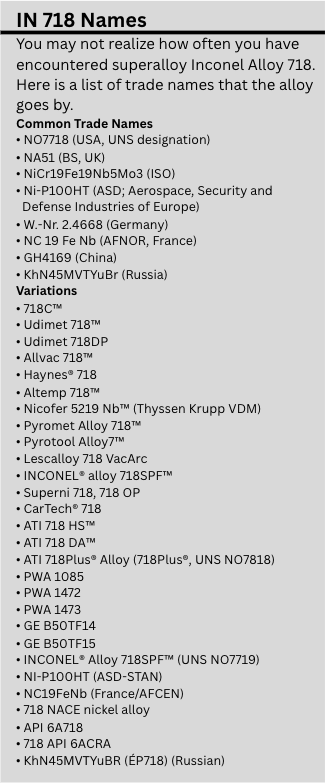
IN 718 is an alloy used around the world, but you might know it better by one of a variety of trade names (see sidebar).

The alloy has been modified numerous times to extend its operating temperature and service life. The alloy is readily available in all of these modified variations, each having slight differences in chemistry, cast and wrought processing methods, and heat treatments.

Applications

There is a wide variety of IN 718 applications across many industries, including aerospace, nuclear, oil and gas, automotive, motorsport, chemical processing, non-nuclear power generation, medical, tooling and molds, and fire protection systems.

In the automotive and motorsport industry, IN 718 is used for turbocharger rotors, exhaust manifolds, and valve springs in high-performance engines, such as those found in Formula 1 or the 24 Hours of Le Mans race cars. Naval warships are also purported to use IN 718 for components in their nuclear reactors (Table A).

Table A. Possible Uses of IN 718 in Naval Warship Nuclear Reactors
Table B. Oil & Gas Industry Use Examples for IN 718
Figure 1. A “Christmas tree”: the complex assembly of valves, gauges, and controls installed at the surface of a completed oil or gas well which has the primary function of regulating and controlling the flow of oil from the well. | Image Credit: Croft Systems

Perhaps surprisingly, IN 718 is also widely used in the oil and gas industry, which in addition to its many other benefits has remarkable resistance to sulfide and chlorine stress corrosion cracking at both high and low temperatures (Table B). Stress corrosion cracking is a failure mechanism that is caused by a combination of environment, a susceptible material, and the presence of tensile stress. Oil and gas applications like downhole tools, wellhead components, and subsea equipment benefit from IN 718’s other valuable properties as well, some of which include:

  • High strength and toughness at temperatures up to 700°C (1290°F)
  • Excellent resistance to pitting, crevice corrosion, and stress corrosion cracking
  • Sustained strength in hydrogen sulfide (H2S) and CO2-rich environments
  • Good weldability and fabrication

Continuous innovations in processing and material chemistry have enhanced superalloy properties resulting in the extension of its use into other industries, such as the energy and more conventional transportation sectors (Loria 1988).

Production Methods

IN 718 is available in cast and wrought alloy form and follows a stringent production process (Figure 2). Basic melt practices are used, such as vacuum induction melting (VIM), vacuum arc remelting (VAR), and electro-slag remelting (ESR).

Figure 2. Flow diagram of processes widely used to produce superalloys (Data reference: Akca and Gursel 2015)

VIM

The VIM process produces liquid metal under vacuum in an induction-heated crucible. It is used as a primary melting step in the route to producing wrought and cast products. Before being melted, the raw material can be refined and purified, and its composition can be controlled. VIM has been widely used in the manufacture of all types of superalloys, which must be melted under vacuum or in an inert gas atmosphere because of their reactivity with atmospheric oxygen and nitrogen.

VAR

The VAR process, a secondary melting technique, converts VIM-processed electrodes into ingots whose chemical and physical homogeneity have been significantly improved. In this process, a stub is welded to one end of an electrode, which is then suspended over a water-cooled copper crucible. Next, an arc is struck between the end of the electrode and the crucible bottom. Maintaining the arc generates the heat required to melt the electrode, which drips into the crucible and can subsequently be poured into molds. Many inclusions can be removed by flotation or chemical and physical processes before the molten material solidifies.

ESR

The ESR process, another secondary melting technique, is similar to the VAR process, but with notable differences. Remelting does not occur by striking an arc under vacuum. Instead, an ingot is built up in a water-cooled mold by melting a consumable electrode that is immersed in a slag, which is superheated by means of resistance heating. Rather than operating in a vacuum, the process is conducted in air under the molten slag. During melting, metal droplets fall through the molten slag, and chemical reactions reduce sulfur and nonmetallic inclusions. Both ESR and VAR processes allow directional solidification of an ingot from bottom to top, yielding high density and homogeneity in its macrostructure, as well as an absence of segregation and shrinkage cavities.

Casting Methods

IN 718 can also be produced by several casting methods. The most common of these are investment casting and (vacuum) die casting:

  • Investment casting: This process involves creating a wax pattern, coating it with a ceramic shell, melting out the wax, and then pouring molten IN 718 into the ceramic mold.
  • Vacuum die casting: This method uses a vacuum to fill the mold, resulting in a refined grain structure, minimal porosity, and good dimensional reproducibility, making it suitable for components like airfoils.
  • Sand casting: This method is far less common due to its inherent limitations in precision and surface finish, but the technology has been used for large castings.

A Metallurgical Perspective: The Role of Gamma Prime and Double Prime

IN 718 is a precipitation hardening superalloy. Its principle strengthening phases are gamma prime (γ′) or Ni3Al and gamma double prime (γ″) or Ni3Nb. The relationship between these precipitates (and others) and the gamma (γ) nickel matrix is critically important. For example, the coherency strain (i.e., the elastic deformation that occurs between two phases when their lattice structures do not perfectly match) is due to the fact that γ′ is face-centered cubic and γ″ is body centered tetragonal. In the case of IN 718, these strengthening effects are influenced more by γ″ than γ′ (ASM International 2016, Lee et al. 2023).

In addition, IN 718 has a natural tendency to precipitate rapidly by homogeneous nucleation in the noncompressible γ matrix. Depending on chemistry, γ′ volume percentage can vary over a wide range (3%–65%). Practically speaking, creep strength is proportional to volume percent over this range at temperatures between 700–980°C (1290–1800°F). As a result, the ratio of titanium to niobium/aluminum is key to hardening. High ratios imparted by niobium assure high strength at intermediate service temperatures around 600°C (1110°F). For higher service temperatures, higher aluminum content and molybdenum additions minimize the γ and γ′ mismatch, thus contributing to more stable alloys (Decker 2006, Guan et al. 2023).

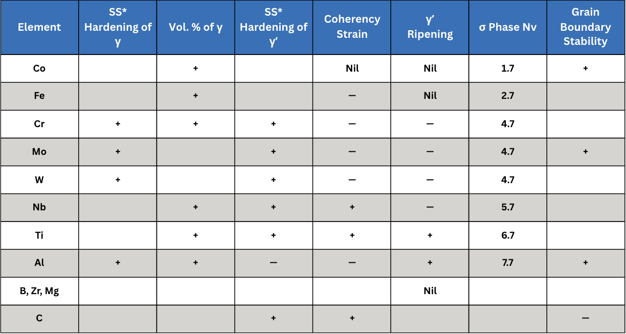
Finally, the size and shape of these precipitates is important; larger precipitates enhance the strengthening effect. Key to the formation of these two precipitates is the aging treatment temperature, time, and alloy composition. According to existing research, higher aging treatment temperatures and longer times can lead to an increased amount of γ″ while extended aging coarsens the γ′ and γ″ particles, potentially leading to a reduction in strength and creep resistance. Furthermore, the composition ratios of Al, Ti, and Nb in the alloy influence the shapes of γ′ and γ″ precipitates, forming so-called co-precipitates that also affect the properties (Table C).

*SS = solid solution; + = enhancement; — = negative effect
Table C. Effect of Various Alloying Elements (Data Reference: Decker 2006)

The highest strength and hardness, coupled with reduced impact toughness, have been observed after heat treatment at 718°C (1325°F), due to an increase in the size and quantity of γ′ and γ″ precipitates.

In addition, as a result of surface analysis of Charpy bars, intergranular fracture occurs due to abundant small-sized precipitates formed within the boundary. In the case of the Charpy impact test, the absorbed energy decreases as the aging temperature increases. The formation of carbide, γ′ and γ″ precipitates can reduce the impact toughness of materials because precipitates may cause more obstacles to dislocation movement and promote crack initiation and propagation (Lee et al. 2023).

This article’s discussion continues in Heat Treat Today’s Annual Aerospace Heat Treat (March 2026) print edition to address heat treatment methods for this superalloy.

References

Akca, Enes, and Gursel, Ali. 2015. “A Review on Superalloys and IN718 Nickel-Based INCONEL Superalloy.” Periodicals of Engineering and Natural Sciences 3 (1): 15–27.

ASM International. 2016. ASM Handbook, Volume 4E: Heat Treating of Nonferrous Alloys. ASM International.

Babu, S. S., N. Raghavan, J. Raplee, S. J. Foster, C. Frederick, M. Haines, R. Dinwiddie, M. K. Kirka, A. Plotkowski, Y. Lee, and R. R. Dehoff. 2018. “Additive Manufacturing of Nickel Superalloys: Opportunities for Innovation and Challenges Related to Qualification.” The Minerals, Metals & Materials Society and ASM International: 3764–3780.

Bradley, Elihu F., ed. 1988. Superalloys: A Technical Guide. ASM International.

Chandler, Harry, ed. 1996. Heat Treater’s Guide: Practices and Procedures for Nonferrous Alloys. ASM International.

Croft Systems. n.d. “The Difference between a Wellhead & Christmas Tree.” https://www.croftsystems.net/oil-gas-blog/the-difference-between-a-wellhead-christmas-tree/

Decker, R. F. 2006. “The Evolution of Wrought Age-Hardenable Superalloy.” Journal of The Minerals, Metals & Materials Society, September: 32–36.

del Bosque, Antonio, Fernández-Arias, Pablo, and Vergara, Diego. 2025. “Advances in the Additive Manufacturing of Superalloys.” Journal of Manufacturing and Materials Processing 9 (215): 1–31.

Eliasen, K. M., T. L. Christiansen, and M. A. J. Somers. 2010. “Low-Temperature Gaseous Nitriding of Ni-Based Superalloys.” Surface Engineering 26 (4): 248–255.

Guan, Hao, Wenxiang Jiang, Junxia Lu, Yuefie Zhang, and Ze Zhang. 2023. “Precipitation of δ Phase in Inconel 718 Superalloy: The Role of Grain Boundary and Plastic Deformation.” Materials Today Communications 36 (August).

Herring, Daniel H. 2011. “Stress Corrosion Cracking.” Industrial Heating, October: 22–24.

Herring, Daniel H. 2012. Vacuum Heat Treating: Principles, Practices, Applications. BNP Media II, LLC.

Herring, Daniel H. 2019. “The Heat Treatment of Inconel 718.” Industrial Heating, June: 12–14.

Lee, Gang Ho, Ang Ho, Minha Park, Byoungkoo Kim, Jong Bae Jeon, Sanghoon Noh, and Byung Jun Kim. 2023. “Evaluation of Precipitation Phase and Mechanical Properties According to Aging Heat Treatment Temperature of Inconel 718.” Journal of Materials Research and Technology 27 (Nov–Dec): 4157–4168. https://doi.org/10.1016/j.jmrt.2023.10.196

Lee, Shin-Chin, Shih-Hsien Chang, Tzu-Piao Tang, Hsin-Hung Ho, and Jhewn-Kuang Chen. 2006. “Improvements in the Microstructure and Tensile Properties of Inconel 718 Superalloy by HIP Treatment.” Materials Transactions 47 (11): 2877–2881.

Loria, Edward A. 1988. “The Status and Prospects of Alloy 718.” Journal of Materials, July: 36–41.

Polasani, Ajay, and Vikram V. Dabhade. 2024. “Heat Treatments of Inconel 718 Nickel-Based Superalloy: A Review.” Metals and Materials International: 1204–1231.

Sharghi-Moshtaghin, Reza, Harold Kahn, Yindong Ge, Xiaoting Gu, Farrel J. Martin, Paul M. Natishan, Arrell J. Martin, Roy J. Rayne, Gary M. Michal, Frank Ernst, and Arthur H. Heuer. 2010. “Low-Temperature Carburization of the Ni-Base Superalloy IN718: Improvements in Surface Hardness and Crevice Corrosion Resistance.” Metallurgical and Materials Transactions A 41A (August): 2022–2032. https://doi.org/10.1007/s11661-010-0299-y

Shipley, Jim. 2023. “Hot Isostatic Pressing and AM: How to Improve Product Quality and Productivity for Critical Applications.” Metal AM 9 (3).

U.S. Patent No. 3,046,108.

Acknowledgments: This paper would not have been possible without discussions, guidance and contributions from a number of individuals in both the heat treat industry and academia.

Special Note: Inconel® is a registered trademark of Special Metals Corporation group of companies.

About the Authors:

Dan Herring
“The Heat Treat Doctor®”
The HERRING GROUP

Dan Herring, who is most well known as The Heat Treat Doctor®, has been in the industry for over 50 years. He spent the first 25 years in heat treating prior to launching his consulting business, The HERRING GROUP, in 1995. His vast experience in the field includes materials science, engineering, metallurgy, equipment design, process and application specialist, and new product research. He is the author of six books and over 700 technical articles.

Nikolai Alexander Hurley
Intern
The Heat Treat Doctor®

Nikolai Alexander Hurley is a young academic, interning with The Heat Treat Doctor®.

For more information: Contact Dan at dherring@heat-treat-doctor.com.

IN 718 Part 1: History, Applications, and Production Read More »

Ask The Heat Treat Doctor®: Why Use Partial Pressure in Vacuum Furnaces?

Ask The Heat Treat Doctor® has returned to bring sage advice to Heat Treat Today readers and to answer your questions about heat treating, brazing, sintering, and other types of thermal treatments as well as questions on metallurgy, equipment, and process-related issues. In this installment, Dan Herring explains how partial pressure atmospheres prevent evaporation and achieve bright, oxide-free parts in vacuum furnaces.

This informative piece was first released in Heat Treat Today’s December 2025 Annual Medical & Energy Heat Treat print edition.

Have questions or feedback? We’d love to hear from you — reach out to our editorial team at editor@heattreattoday.com.


Operating in vacuum can often lead to problems related to evaporation, that is, literally “boiling away” elements present in the materials being heat treated. This affects surface integrity, functionality, performance, and in some rare cases altering the chemical composition of the base (or filler) metal.

One way to overcome this problem is to introduce a gas partial pressure higher than that of the material’s vapor pressure. Different gas choices, introduction methods, and controls are available to the heat treater. The natural question is, how and when should they be used? Let’s learn more.

What is Partial Pressure?

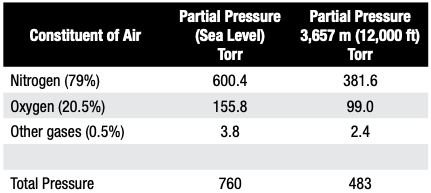
In simplest terms, the partial pressure of a gas introduced into a vacuum furnace is the force exerted by that gas (or gases) constrained in the vacuum vessel. If only a single gas is present, the partial pressure of the system is the same as the total pressure. For a multi-gas system, air is a good example to look at. At sea level with atmospheric pressure 760 torr (760 mm Hg) and at an altitude of 3,657 m (12,000 ft), the atmospheric pressure is only 483 Torr (Table A).

Table A. Partial Pressure of Individual Gases Present in Air | Source: Jones 1997

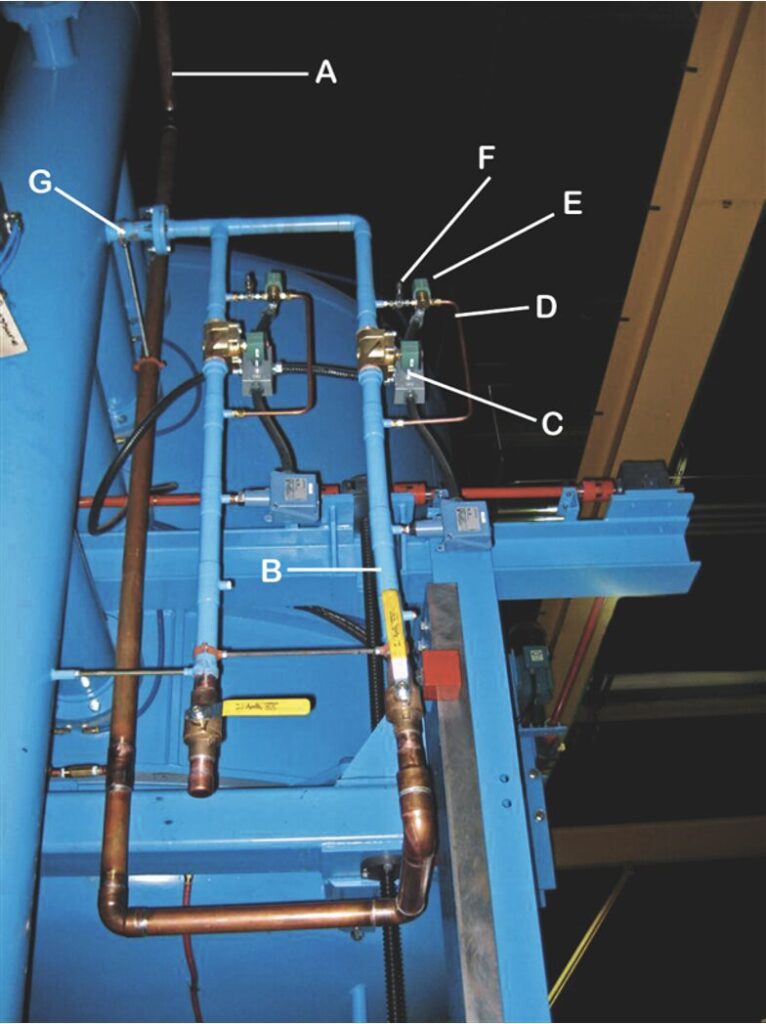
In vacuum systems, when the chamber atmosphere is evacuated to a high enough vacuum level — commonly between 10⁻³ Torr (0.1 micron) and 10⁻⁵ Torr (0.01 microns) — issues of evaporation are likely to occur during heat up and holding at temperature. As such, nitrogen or a truly inert gas is introduced below a predetermined temperature at a controlled rate to a fixed partial pressure range and then controlled within this range. One then isolates the high vacuum portion of the pumping system and employs bypass circuitry using the mechanical pump to introduce a continuous flow of gas equal to the pumping capacity (throughput) at the required operating pressure (Figure 1 below).

Figure 1. Typical partial pressure piping on a vacuum furnace
Key:
A: Incoming gas supply line
B: Backfill line
C: Quench solenoid
D: Partial pressure line
E: Partial pressure solenoid valve
F: Partial pressure (micrometer) needle value
G: Inlet into furnace
Source: Courtesy of Vac-Aero International

Why Do We Need to Use Partial Pressure in a Vacuum Furnace?

There is no hard and fast rule for partial pressure settings used for processing various materials in the heat treat industry. However, from a practical standpoint, there are two process considerations for determining partial pressure. The first is the metal-oxide reduction partial pressure. The partial pressure of oxygen at a given temperature determines the direction of the reaction and consequently whether the part is “bright” or “discolored” (oxidized). These values are typically in the range of 10⁻⁶ Torr to 10⁻² Torr. This is why materials like titanium alloys and superalloys must be processed at extremely low vacuum levels. The second consideration is the vaporization of metal at high temperature and hard vacuum. The metal solid-to-vapor partial pressures require higher pressures to avoid alloy depletion. These higher pressures often produce sufficient dilutions of contaminants to drive the reaction to be reducing.

What is often overlooked or misunderstood is that higher levels of partial pressure “dilute” any oxygen or water vapor partial pressure but still can produce oxide free “bright” parts at higher pressures. This dilution also occurs, for example when a retort is purged with nitrogen or argon to achieve clean parts. The oxygen partial pressure is reduced by dilution rather than by vacuum. In addition, it cannot be overemphasized that oxidation present on parts from exposure to the atmosphere and moisture absorbed by the furnace lining when the door is open are critical in running clean work. Oxidation occurs on heat up, but when the temperature is high enough and conditions are right, we can reverse the oxidation reaction so the parts will clean up. This is why it is harder to bright temper than to bright harden.

In batch vacuum furnaces, combination hardening and tempering cycles are used to take advantage of the furnace configuration in which parts stay in the furnace for the full process. Often, the same parts will discolor if tempered in the same furnace after they have been removed and the furnace exposed to air.

Also, a thorough understanding of the required component properties and material characteristics (e.g. alloy composition, grain size, hardenability response) is needed to design the final vacuum heat treat cycles and select the final partial pressure settings.

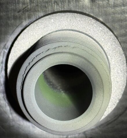
Figure 2. Chromium deposits / discoloration in the area of a graphite cooling nozzle | Source: The HERRING Group, Inc

For example, stainless steels, tool steels, and more exotic alloys run in a vacuum furnace will benefit substantially from the use of partial pressure atmospheres. In most heat treat shops, partial pressure cycles begin around 760°C (1400°F) at pressure from 1–1.5 Torr (1000–1500 microns). This is primarily because chromium present in many of these materials and in our baskets/fixtures evaporates noticeably at temperatures and pressures within normal heat treatment ranges. At around 990°C (1800°F), chromium will vaporize rapidly as a function of both vacuum level and time. In general, the practical operating vacuum level for most materials is significantly above their equilibrium vapor pressures. It is also helpful at times to know the temperature at which individual elements exceed a critical (10⁻⁶ g/cm²-s) vaporization rate (Herring 2015).

In practice, heat treaters often observe greenish discoloration (chromium oxide) on the interior of their vacuum furnaces (Figure 2), the result of chromium vapor reacting with air leaking into the hot zone. Otherwise, the evaporation deposit is bright and mirror-like. To avoid these types of deposits contaminating both the furnace and the parts run in it, an operating partial pressure between 1 Torr and 5 Torr (1,000 microns to 5,000 microns) is typical for parts that will boil away their elemental constituents.

Chromium Coloration

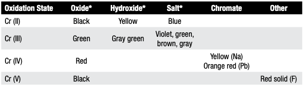
Heat treaters should be aware that although the most common color of chromium discoloration is green, the color is dependent on chromium’s oxidation state (Table B). For example, Cr (II) compounds typically appear blue, Cr (III) compounds appear green, and Cr (VI) compounds appear orange or red.

Notes: * Most commonly observed colors
Table B. Oxidation Colors of Chromium and Chromium Compounds

Table B provides a more detailed breakdown of chromium’s oxidation states and associated colors.

Which Partial Pressure Gas(es) Can We Use?

Argon, nitrogen, and hydrogen are the most common partial pressure gases. Often, argon is preferred as it is a truly inert gas and tends to “sweep” the hot zone; that is, being a heavier molecule, it tends to reduce evaporation compared with nitrogen or hydrogen. Specialized applications, such as those in the electronics industry, may use helium or even neon (if an ionizing gas is needed). Gases having a minimum purity of 99.99% and a dew point of -60°C (-76°F) or lower should be specified.

Certain cautions are in order. For example, nitrogen may react with certain stainless steels and titanium bearing alloys resulting in surface nitriding. In the case of hydrogen, the normally near neutral vacuum atmosphere can be sharply shifted to a reducing atmosphere to prevent oxidation of sensitive process work or for furnace/fixture bakeout/cleanup cycles. Embrittlement by hydrogen is a concern for certain materials (e.g., Ti, Ta).

In Summary

Partial pressure atmospheres are required in many heat treating and brazing operations to achieve desired results. Introduction of the partial pressure gas into the furnace hot zone at one or more locations and controlling the partial pressure injection gas stream as a continuous flow, rather than trying to operate at a specific pressure, are critical considerations. The choice of partial pressure gas is also important both from a cost and quality standpoint.

References

Herring, Daniel H. 2014. Vacuum Heat Treatment. Vol. 1. Troy, MI: BNP Media.

Herring, Daniel H. 2015. Vacuum Heat Treatment. Vol. 2. Troy, MI: BNP Media.

Houghton, R., Jr. n.d. Private correspondence, Spectrum Thermal Processing.

Jones, W. R. 1997. “Partial Pressure Vacuum Processing – Part I and II.” Industrial Heating, September/October.

Jones, William. n.d. Private correspondence, Solar Atmospheres Inc.

Fabian, R., ed. 1993. Vacuum Technology: Practical Heat Treating and Brazing. Materials Park, OH: ASM International.

The Boeing Company. n.d. “Practical Vacuum Systems Design Course.”

About the Author

Dan Herring
“The Heat Treat Doctor”
The HERRING GROUP, Inc.

Dan Herring has been in the industry for over 50 years and has gained vast experience in fields that include materials science, engineering, metallurgy, new product research, and many other areas. He is the author of six books and over 700 technical articles.

For more information: Contact Dan at dherring@heat-treat-doctor.com.

For more information about Dan’s books: see his page at the Heat Treat Store.


Ask The Heat Treat Doctor®: Why Use Partial Pressure in Vacuum Furnaces? Read More »

Nitruración anódica por plasma de aleaciones de titanio

En esta entrega de Martes Técnico, el Dr. Edward Rolinski y Dan Herring, conocidos respectivamente como “Doctor Glow” y The Heat Treat Doctor®, exploran cómo el nitrurado por plasma anódico para aleaciones de titanio evita los efectos dañinos del nitrurado catódico convencional mientras mejora la resistencia al desgaste, la resistencia a la corrosión y la confiabilidad de los componentes para aplicaciones aeroespaciales y médicas.

Este artículo informativo se publicó por primera vez en Heat Treat Today’s November 2025 Annual Vacuum Heat Treating print edition.

Para leer el artículo en inglés, haga clic aquí.


La nitruración tradicional por plasma/iónica es una tecnología consolidada. Sin embargo, presenta problemas que pueden solucionarse con el nuevo método de nitruración anódica por plasma. Este artículo presenta la idea de utilizar la nitruración anódica por plasma para titanio y aleaciones de titanio, evitando así los efectos perjudiciales de la nitruración catódica por plasma convencional. Descubra cómo este enfoque podría proporcionar capas más duras y sin defectos que mejoran el desgaste, la resistencia a la corrosión y la fiabilidad general de los componentes para piezas críticas de la industria aeroespacial y médica.

Qué es la nitruración anódica?

La nitruración anódica es un tipo de proceso de nitruración por plasma en el que las piezas tratadas se ubican en un potencial anódico (positivo) en lugar del potencial catódico (negativo) habitual. A diferencia de la nitruración por plasma convencional (descarga catódica), donde el componente se bombardea con iones positivos de alta energía, la nitruración anódica implica el bombardeo de electrones de baja energía sobre la superficie del componente.

La nitruración anódica es particularmente efectiva para materiales con una alta energía libre estándar negativa de formación de nitruros (p. ej., titanio, circonio), ya que ayuda a evitar o reducir el efecto de borde, un problema bien conocido en la nitruración catódica que provoca un bombardeo iónico desigual y endurecimiento en esquinas y bordes.

Antecedentes: Complejidades de la nitruración por plasma

La nitruración por plasma con descarga luminiscente se aplica a una amplia gama de materiales, como fundiciones, aceros al carbono, aceros inoxidables, níquel, aleaciones de titanio y pulvimetalurgia (Roliński, 2014). Los procesos de nitruración por plasma y nitrocarburación permiten la formación de capas superficiales con propiedades tribológicas superiores (Roliński, 2014). Sin embargo, la cobertura de las piezas con la descarga luminosa no siempre es uniforme, especialmente cuando se procesan cargas de geometría compleja (véase la Figura 1).

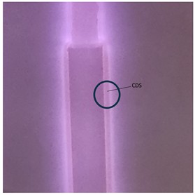
La nitruración por plasma de baja descarga es un tratamiento termoquímico que utiliza partículas de alta energía. Los iones de nitrógeno u otras especies gaseosas se aceleran y ganan energía en el espacio oscuro de Crookes (CDS) alrededor de la pieza, que es el cátodo en una configuración de electrodos de corriente directa. Primero activan la superficie mediante pulverización catódica (sputtering) para eliminar cualquier óxido nativo presente. El tratamiento de pulverización catódica también genera una cantidad sustancial de partículas sólidas, generadas por la propia pieza, incluyendo átomos metálicos que flotan cerca de la superficie (Merlino y Goree, 2004; Roliński, 2005). En el procesamiento del titanio, por ejemplo, esto afecta tanto la adsorción como la difusión en la superficie, creando condiciones que degradan la calidad de la capa (Hubbard, et al., 2010). Se ha descrito un impacto negativo de este plasma “polvoriento” en la uniformidad de la capa nitrurada en piezas de geometría compleja (Ossowski et al., 2016).

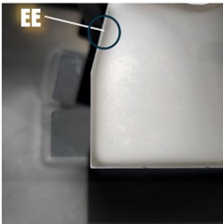
Además, es bien sabido que durante la nitruración por plasma se observa el denominado efecto esquina/borde (EE), relacionado con la circulación desigual de estas partículas de polvo alrededor del cátodo (véase la Figura 2). En situaciones extremas, especialmente al tratar piezas de geometría compleja, el EE, causado por una distribución desigual del campo eléctrico en esquinas, cavidades, etc., da lugar a una distribución excesiva y desigual de estos depósitos de plasma (PD). De esta manera, el EE agrava el problema ya existente de la redeposición, lo que provoca la formación de diversos microdefectos y un espesor desigual de la capa nitrurada (Merlino y Goree, 2004; Roliński, 2005, 2024; Ossowski et al., 2016).

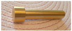
Figura 3. Componente de titanio después de nitruración gaseosa en amoníaco. Source: Roliński and Herring

La nitruración por plasma del titanio se realiza habitualmente a 680–1100 °C (1256–2012 °F). Entre los aspectos negativos del uso de la polarización catódica en titanio se incluyen el bombardeo de plasma/iónico, que provoca daños superficiales debido principalmente a micro-arcos y la contaminación de la superficie con los compuestos depositados, así como su distribución desigual debido al EE (Merlino y Goree, 2004; Roliński, 2005, 2014, 2024; Ossowski et al., 2016). Aunque el arco eléctrico se ha eliminado mediante la aplicación de técnicas de plasma pulsado, la pulverización catódica solo se puede controlar de forma limitada, especialmente cuando se nitruran piezas de geometría compleja. Por lo tanto, la nitruración gaseosa en amoníaco se ha utilizado ocasionalmente para endurecer piezas de titanio. Se produce un aspecto dorado resultante en la superficie que indica la presencia del nitruro TiN (véase la Figura 3).

Nitruración anódica de aleaciones de titanio

Se han realizado investigaciones sobre la nitruración anódica de aceros por plasma (Zlatanovic 1986; Michalski 1993; Kenĕz 2018). El amoníaco o las especies de nitrógeno activo generadas en el plasma pueden nitrurar el ánodo al igual que al cátodo. Las especies activas que causan la nitruración son átomos de nitrógeno activo y radicales NH altamente reactivos (NH*) formados en el plasma cercano. Los radicales NH (también conocidos como radicales imidógenos) son especies químicas con un enlace nitrógeno-hidrógeno junto con un electrón desapareado. En el caso del titanio, el hidrógeno debe excluirse en muchas situaciones, ya que reacciona con el titanio para formar hidruros estables que fragilizan el producto (Roliński, 2015).

La entalpía libre estándar de formación de nitruros de titanio tiene un valor negativo excepcionalmente alto, lo que significa que el nitruro de titanio se formará espontáneamente cuando el ánodo de titanio reaccione con nitrógeno excitado cercano (Roliński, 2015). Cambiar de polarización catódica a anódica de los componentes tratados ofrece varias ventajas notables. Una descarga luminosa en nitrógeno puro o argón genera únicamente iones positivos que se aceleran hacia el cátodo/pieza de trabajo. Dado que estas mezclas de gases carecen de iones negativos, solo los electrones de la luminiscencia anódica inciden en el ánodo/pieza de trabajo. Esto produce la activación de la superficie sin los efectos negativos de las colisiones de partículas más pesadas, como N₂+ (es decir, un ion molecular de nitrógeno con carga +1), lo que provoca una pulverización catódica excesiva. Al mismo tiempo, partículas de nitrógeno sin carga, como N₂* y N*, reaccionan con el ánodo por quimisorción en la superficie a una temperatura suficientemente alta, lo que finalmente conduce a la formación de la capa de difusión.

Se cree que el proceso de nitruración anódica puede tener efectos positivos en el tratamiento de piezas de precisión de titanio y otras aleaciones para su uso en las industrias aeroespacial y médica. Este método permitirá el tratamiento a la temperatura más baja posible gracias a la activación de la superficie con los electrones de la polarización anódica. La textura, la apariencia y una superficie sin defectos producirán una pieza superior y mejorarán el rendimiento de muchos de esos componentes. Esto será importante cuando la corrosión o las propiedades ópticas de la superficie sean importantes.

La nitruración anódica del titanio puede lograrse mediante un sistema convencional de nitruración por plasma, siempre que el ánodo central esté diseñado y ubicado adecuadamente. Este ánodo, o parte del mismo, debe estar hecho de titanio para evitar la evaporación y la transferencia de impurezas a las piezas.

Aplicaciones

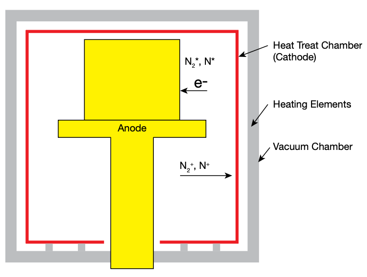
Figura 4. Representación esquemática del aparato de nitruración por plasma anódico. Observe el color dorado característico del nitruro de titanio (TiN) presente en los accesorios y piezas de titanio, todos identificados como “ánodo”. Source: Roliński and Herring

Las aleaciones de titanio son populares en ortopedia debido a su elasticidad, resistencia y biocompatibilidad similares a las del hueso (Roliński 2015; Froes 2015). Los procesos de ingeniería de superficies, como la nitruración anódica, pueden desempeñar un papel importante a la hora de prolongar el rendimiento de los dispositivos ortopédicos varias veces más allá de su vida útil normal.

Los materiales intermetálicos superelásticos, como el 60NiTi, se utilizan en elementos de rodamientos debido a su resistencia a la corrosión y al impacto (Pohrelyuk et al., 2015; Corte et al., 2015). Suelen ser propensos a la degradación por fatiga de contacto rodante (RCF). Cualquier defecto superficial presente en estos componentes, como la concentración local de impurezas o microfisuras, provocará un fallo prematuro. La nitruración por plasma anódico puede utilizarse para endurecer las superficies de los componentes de rodamientos fabricados con estas aleaciones, formando una capa dura y sin defectos, lo que puede mejorar sus propiedades ante el RCF.

Se espera que las piezas de titanio u otras aleaciones con la superficie sometida a nitruración anódica estén libres de micro-defectos, lo que permite su amplia aplicación en el campo médico, la industria aeroespacial y los dispositivos ópticos y semiconductores.

Referencias

Corte, Ch. Della, M. K. Stanford, and T. R. Jett. 2015. “Rolling Contact Fatigue of Superelastic Intermetallic Materials (SIM) for Use as Resilient Corrosion Resistant Bearings.” Tribology Letters 26: 1–10.

Froes, F. H., ed. 2015. Titanium: Physical Metallurgy, Processing and Applications. Materials Park, OH: ASM International.

Hubbard, P., J. G. Partridge, E. D. Doyle, D. G. McCulloch, M. B. Taylor, and S. J. Dowey. 2010. “Investigation of Mass Transfer within an Industrial Plasma Nitriding System I: The Role of Surface Deposits.” Surface and Coatings Technology 204: 1145–50.

Kenĕz, L., N. Kutasi, E. Filep, L. Jakab-Furkas, and L. Ferencz. 2018. “Anodic Plasma Nitriding in Hollow Cathode (HCAPN).” HTM Journal of Heat Treatment and Materials 73 (2): 96–105.

Merlino, R. L., and J. A. Goree. 2004. “Dusty Plasmas in the Laboratory, Industry, and Space.” Physics Today, July, 32–38.

Michalski, J. 1993. “Ion Nitriding of Armco Iron in Various Glow Discharge Regions.” Surface and Coatings Technology 59 (1–3): 321–24. https://doi.org/10.1016/0257-8972(93)90105-W.

Ossowski, Maciej, Tomasz Borowski, Michal Tarnowski, and Tadeusz Wierzon. 2016. “Cathodic Cage Plasma Nitriding of Ti6Al4V.” Materials Science (Medžiagotyra) 22 (1).

Pohrelyuk, I., V. Fedirko, O. Tkachuk, and R. Poskurnyak. 2015. “Corrosion Resistance of Ti-6Al-4V Alloy with Oxidized Nitride Coatings in Ringer’s Solution.” Inzynieria Powierzchni (Surface Engineering) 1: 38–46.

Roliński, E. 2014. “Plasma Assisted Nitriding and Nitrocarburizing of Steel and Other Ferrous Alloys.” In Thermochemical Surface Engineering of Steels, edited by E. J. Mittemeijer and M. A. J. Somers, 413–57. Woodhead Publishing Series in Metals and Surface Engineering 62. Cambridge, UK; Waltham, MA; and Kidlington, UK: Woodhead Publishing.

Roliński, E. 2015. “Nitriding of Titanium Alloys.” In ASM Handbook, Volume 4E: Heat Treating of Nonferrous Alloys, edited by G. E. Totten and D. S. McKenzie, 604–21. Materials Park, OH: ASM International.

Roliński, Edward. 2024. “Practical Aspects of Sputtering and Its Role in Industrial Plasma Nitriding.” In ASM Handbook Online, Volume 5: Surface Engineering. Materials Park, OH: ASM International. https://doi.org/10.31399/asm.hb.v5.a0007039.

Roliński, E., J. Arner, and G. Sharp. 2005. “Negative Effects of Reactive Sputtering in an Industrial Plasma Nitriding.” Journal of Materials Engineering and Performance 14 (3): 343–50.

Zlatanovic, M., A. Kunosic, and B. Tomčik. 1986. “New Development in Anode Plasma Nitriding.” In Proceedings of the International Conference on Ion Nitriding, Cleveland, OH, September 15–17, edited by T. Spalvins, 47–51. Cleveland, OH: NASA Lewis Research Center.

About The Authors:

Dr. Edward Rolinski
“Doctor Glow”

El Dr. Edward Rolinski, conocido afectuosamente como “Doctor Glow”, es un distinguido científico sénior que ha liderado la investigación sobre nitruración por plasma/iones desde la década de 1970. Posee títulos avanzados en tecnología de fabricación y metalurgia, incluyendo un doctorado en Ciencias. Se ha centrado en los procesos de nitruración por plasma, especialmente en aleaciones de titanio y pulvimetalurgia. A lo largo de su carrera, el Dr. Rolinski ha sido autor de numerosos capítulos y artículos técnicos influyentes, incluyendo para ASTM International y el Manual ASM, y es un prolífico colaborador en publicaciones del sector. Tras décadas de liderazgo e innovación en ingeniería de superficies y tratamiento térmico, ahora es un consultor en la industria del tratamiento térmico.

Dan Herring
(The Heat Treat Doctor®)
The HERRING GROUP, Inc.

Dan Herring, conocido como The Heat Treat Doctor®, lleva más de 50 años en la industria. Dedicó sus primeros 25 años al tratamiento térmico antes de fundar su empresa de consultoría, The HERRING GROUP, en 1995. Su amplia experiencia en el campo abarca la ciencia de los materiales, la ingeniería, la metalurgia, el diseño de equipos, la especialización en procesos y aplicaciones, y la investigación de nuevos productos. Es autor de seis libros y más de 700 artículos técnicos.

Para más información: Contacte con Dan en dherring@heat-treat-doctor.com.

Nitruración anódica por plasma de aleaciones de titanio Read More »

Anodic Plasma Nitriding of Titanium Alloys

In this Technical Tuesday installment, Dr. Edward Rolinski and Dan Herring, respectively known as “Doctor Glow” and The Heat Treat Doctor®, explore how anodic plasma nitriding for titanium alloys avoids the damaging effects of conventional cathodic nitriding while improving wear resistance, corrosion resistance, and component reliability for aerospace and medical applications.

This informative piece was first released in Heat Treat Today’s November 2025 Annual Vacuum Heat Treating print edition.

To read the article in Spanish, click here.


Traditional plasma/ion nitriding is a well-established technology. However, it has issues that can be overcome by the newer anodic plasma nitriding method. This article introduces the idea of using anodic plasma nitriding for titanium and titanium alloys to avoid the damaging effect of conventional (cathodic) plasma nitriding. Read how this approach could provide harder, defect-free layers that improve wear, corrosion resistance, and overall component reliability for aerospace and medical critical parts.

What Is Anodic Nitriding?

Anodic nitriding is a type of plasma nitriding process in which the component parts being treated are placed at an anodic (positive) potential instead of the usual cathodic (negative) potential. Unlike conventional plasma (cathodic glow discharge) nitriding, where the component is bombarded by high-energy positive ions, anodic nitriding involves low-energy electron bombardment of the component’s surface.

Anodic nitriding is particularly effective for materials with very high negative Standard Free Energy of nitride formation (e.g., titanium, zirconium) as it helps avoid or reduce the edge effect, a well-known problem in cathodic nitriding that leads to uneven ion bombardment and hardening on corners and edges.

Background: Plasma Nitriding Complexities

Glow-discharge plasma nitriding is applied to a wide range of materials, including cast irons, carbon steels, stainless steels, nickel, titanium alloys, and powder metal (Roliński 2014). The plasma nitriding and nitrocarburizing processes allow for the formation of surface layers known to have superior tribological properties (Roliński 2014). However, coverage of the parts with the glow discharge is not always uniform, especially when complex geometry loads are processed (see Figure 1).

Glow-discharge plasma nitriding is a thermochemical treatment involving high-energy particles. Ions of nitrogen or other gas species accelerate and gain energy in the cathodic dark space (CDS) around the workpiece — which is the cathode in a direct current electrode setup. They activate the surface first by sputtering to remove any native oxides present. The sputtering treatment also results in the generation of a substantial quantity of solid particles, generated from the part itself, including metal atoms that levitate near the surface of the part (Merlino and Goree 2004; Roliński 2005). In processing titanium, for example, this affects both adsorption and diffusion at the surface creating conditions that degrade layer quality (Hubbard, et al. 2010). A negative impact of this “dusty” plasma on the uniformity of the nitrided layer in complex-geometry workpieces has been reported (Ossowski, et al. 2016).

In addition, it is well known that there is a so-called corner/edge effect (EE) observed during plasma nitriding related to uneven circulation of these dust particles around the cathode (see Figure 2). In extreme situations, especially when complex geometry parts are treated, the EE caused by a non-uniform distribution of the electric field on corners, cavities, etc., results in excessive and non-uniform distribution of these plasma deposits (PD). In this way, the EE amplifies the already-present problem of redeposition, leading to the formation of various microdefects and uneven nitrided layer thickness (Merlino and Goree 2004; Roliński 2005, 2024; Ossowski, et al. 2016).

Figure 3. Titanium component after gas nitriding in ammonia | Source: Roliński and Herring

Plasma nitriding of titanium is usually performed at 680–1100°C (1256–2012°F). Negative aspects of using cathodic polarization on titanium include plasma/ion bombardment resulting in surface damage due primarily to micro arcing and contamination of the surface with the deposited compounds and their uneven distribution due to EE (Merlino and Goree 2004; Roliński 2005, 2014, 2024; Ossowski, et al. 2016). Although arcing has been eliminated by applying pulse plasma techniques, sputtering can only be controlled in a limited way, especially when complex geometry parts are nitrided. Therefore, gas nitriding in ammonia has been used occasionally for hardening titanium parts. A resulting golden appearance representing the presence of TiN nitride is produced on the surface (see Figure 3).

Anodic Nitriding of Titanium Alloys

Research has been conducted on anodic plasma nitriding of steels (Zlatanovic 1986; Michalski 1993; Kenĕz 2018). Ammonia or active nitrogen species generated in the plasma can nitride the anode just as they do the cathode. The active species causing nitriding are active nitrogen atoms and highly reactive NH radicals (NH*) formed in near plasma. NH radicals (aka imidogen radicals) are chemical species with a nitrogen-hydrogen bond along with an unpaired electron. For titanium, hydrogen must be excluded in many situations because it reacts with titanium to form stable hydrides that embrittle the product (Roliński 2015).

The standard free enthalpy of formation of titanium nitrides has an exceptionally large negative value, which means that titanium nitride will form in a spontaneous way when the titanium anode reacts with excited nitrogen nearby (Roliński 2015). Switching the treated components from cathodic to anodic polarization offers several notable advantages. A glow discharge in pure nitrogen or argon generates only positive ions that are accelerated toward the cathode/workpiece. Because these gas mixtures lack negative ions, only electrons from the anodic glow strike the anode/workpiece. This results in activation of the surface without negative aspects of the collisions of the heavier particles, such as N2+ (i.e., a nitrogen molecular ion with a +1 charge), causing excessive sputtering. At the same time, charge-free particles of nitrogen, such as N2* and N*, react with the anode and are chemisorbed at the surface at sufficiently high temperature, leading eventually to formation of the diffusion layer.

It is believed that the anodic-nitriding process may have positive effects in treating precision parts made of titanium and other alloys for use in both the aerospace and medical industries. This method will allow treatment at the lowest possible temperature due to activation of the surface with the electrons from anodic polarization. The texture, appearance, and defect-free surface will produce a superior part and will enhance the performance of many of those components. This will be important when corrosion or optical properties of the surface play a significant role.

Anodic nitriding of titanium can be accomplished within a conventional plasma nitriding system, provided that the central anode is appropriately designed and positioned. This anode or portion of it must be made of titanium to prevent evaporation and transfer of any impurities to the parts.

Applications

Figure 4. Schematic representation of the anodic plasma nitriding apparatus. Note the gold color characteristic for titanium nitride TiN present on the titanium fixturing and parts, all being identified as “anode.” | Source: Roliński and Herring

Titanium alloys are popular in orthopedics due to their bone-like elasticity, strength, and biocompatibility (Roliński 2015; Froes 2015). Surface engineering processes like anodic nitriding can play a significant role in extending the performance of orthopedic devices several times beyond their normal life expectancy.

Super elastic intermetallic materials, such as 60NiTi, are used in rolling element bearings due to their resistance to corrosion and shock (Pohrelyuk, et al. 2015; Corte, et al. 2015). They are typically prone to rolling contact fatigue (RCF) degradation. Any surface defects present in those components, such as local concentration of impurities or micro-cracks, will result in premature failure. Anodic plasma nitriding can be potentially used to harden the surfaces of bearing components made from these alloys by forming a hard, defect-free layer, which may improve their RCF properties.

It is expected that parts made of titanium or other alloys with the smooth surface subjected to the anodic nitriding will be microdefects-free, enabling their broad applications in medical field, aerospace industry, and optical and semiconductor devices.

References

Corte, Ch. Della, M. K. Stanford, and T. R. Jett. 2015. “Rolling Contact Fatigue of Superelastic Intermetallic Materials (SIM) for Use as Resilient Corrosion Resistant Bearings.” Tribology Letters 26: 1–10.

Froes, F. H., ed. 2015. Titanium: Physical Metallurgy, Processing and Applications. Materials Park, OH: ASM International.

Hubbard, P., J. G. Partridge, E. D. Doyle, D. G. McCulloch, M. B. Taylor, and S. J. Dowey. 2010. “Investigation of Mass Transfer within an Industrial Plasma Nitriding System I: The Role of Surface Deposits.” Surface and Coatings Technology 204: 1145–50.

Kenĕz, L., N. Kutasi, E. Filep, L. Jakab-Furkas, and L. Ferencz. 2018. “Anodic Plasma Nitriding in Hollow Cathode (HCAPN).” HTM Journal of Heat Treatment and Materials 73 (2): 96–105.

Merlino, R. L., and J. A. Goree. 2004. “Dusty Plasmas in the Laboratory, Industry, and Space.” Physics Today, July, 32–38.

Michalski, J. 1993. “Ion Nitriding of Armco Iron in Various Glow Discharge Regions.” Surface and Coatings Technology 59 (1–3): 321–24. https://doi.org/10.1016/0257-8972(93)90105-W.

Ossowski, Maciej, Tomasz Borowski, Michal Tarnowski, and Tadeusz Wierzon. 2016. “Cathodic Cage Plasma Nitriding of Ti6Al4V.” Materials Science (Medžiagotyra) 22 (1).

Pohrelyuk, I., V. Fedirko, O. Tkachuk, and R. Poskurnyak. 2015. “Corrosion Resistance of Ti-6Al-4V Alloy with Oxidized Nitride Coatings in Ringer’s Solution.” Inzynieria Powierzchni (Surface Engineering) 1: 38–46.

Roliński, E. 2014. “Plasma Assisted Nitriding and Nitrocarburizing of Steel and Other Ferrous Alloys.” In Thermochemical Surface Engineering of Steels, edited by E. J. Mittemeijer and M. A. J. Somers, 413–57. Woodhead Publishing Series in Metals and Surface Engineering 62. Cambridge, UK; Waltham, MA; and Kidlington, UK: Woodhead Publishing.

Roliński, E. 2015. “Nitriding of Titanium Alloys.” In ASM Handbook, Volume 4E: Heat Treating of Nonferrous Alloys, edited by G. E. Totten and D. S. McKenzie, 604–21. Materials Park, OH: ASM International.

Roliński, Edward. 2024. “Practical Aspects of Sputtering and Its Role in Industrial Plasma Nitriding.” In ASM Handbook Online, Volume 5: Surface Engineering. Materials Park, OH: ASM International. https://doi.org/10.31399/asm.hb.v5.a0007039.

Roliński, E., J. Arner, and G. Sharp. 2005. “Negative Effects of Reactive Sputtering in an Industrial Plasma Nitriding.” Journal of Materials Engineering and Performance 14 (3): 343–50.

Zlatanovic, M., A. Kunosic, and B. Tomčik. 1986. “New Development in Anode Plasma Nitriding.” In Proceedings of the International Conference on Ion Nitriding, Cleveland, OH, September 15–17, edited by T. Spalvins, 47–51. Cleveland, OH: NASA Lewis Research Center.

About The Authors:

Dr. Edward Rolinski
“Doctor Glow”

Dr. Edward Rolinski, affectionately known as “Doctor Glow,” is a distinguished senior scientist having spearheaded research on plasma/ion nitriding since the 1970s. He holds advanced degrees in manufacturing technology and metallurgy, including a PhD and Doctor of Science. His focus has been on plasma nitriding processes, especially involving titanium alloys and powder metallurgy. Over his career, Dr. Rolinski authored numerous influential technical chapters and articles, including for ASTM International and the ASM Handbook, and is a prolific contributor to industry publications. After decades of leadership and innovation in surface engineering and heat treating, he is now a consultant in the heat-treating industry.

Dan Herring
(The Heat Treat Doctor®)
The HERRING GROUP, Inc.

Dan Herring, who is most well known as The Heat Treat Doctor®, has been in the industry for over 50 years. He spent the first 25 years in heat treating prior to launching his consulting business, The HERRING GROUP, in 1995. His vast experience in the field includes materials science, engineering, metallurgy, equipment design, process and application specialist, and new product research. He is the author of six books and over 700 technical articles.

For more information: Contact Dan at dherring@heat-treat-doctor.com.

Anodic Plasma Nitriding of Titanium Alloys Read More »

Ask The Heat Treat Doctor®: What Masks the Steel’s Surface in Case Hardening?

Ask The Heat Treat Doctor® has returned to bring sage advice to Heat Treat Today readers and to answer your questions about heat treating, brazing, sintering, and other types of thermal treatments as well as questions on metallurgy, equipment, and process-related issues.

This informative piece was first released in Heat Treat Today’s November 2025 Annual Vacuum Heat Treating print edition.

Case depth, case uniformity, and final mechanical (as well as other) properties rely not only on controlling both equipment and process variability during heat treatment, but on having clean, properly prepared part surfaces prior to and during heat treating. Expert Dan Herring encourages to learn more below.


Case hardening is a thermochemical surface treatment process designed to add a particular element or combination of elements to a material such as steel. Familiar examples include carbon (carburizing); carbon and nitrogen (carbonitriding); boron (boriding); nitrogen (nitriding); and nitrogen and carbon (nitrocarburizing — ferritic or austenitic). These processes are typically designed to increase the near surface hardness of steel after quenching.

However, various problems can arise due to either the materials or the manufacturing methods employed prior to or during heat treating that will retard or prevent absorption and/or diffusion of the desired element(s) during heat treating. Some of the metallurgical consequences can include:

  • Shallow or uneven case depths
  • Surface oxidation
  • Intergranular oxidation or decarburization
  • High levels of retained austenite
  • Soft spots due to incomplete hardening

Machine-Induced Surface Conditions

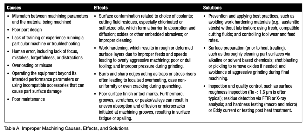
Improper machining prior to case hardening can compromise surface integrity. Tooling choices, improperly maintained equipment, inadequate operator training, and even environmental factors can contribute to a variety of issues.

While machining problems occur frequently, they are mostly preventable. Attention to part surface condition, cleanliness, and mechanical integrity is essential before heat treating. Training, standardizing machining protocols, planned preventative maintenance programs, and part inspection prior to heat treating will help avoid these issues. Consult Table A for further details on how the causes and effects of undesirable machine-induced surface conditions can be solved.

Splatter of Stop-off Paints on Unintended Areas

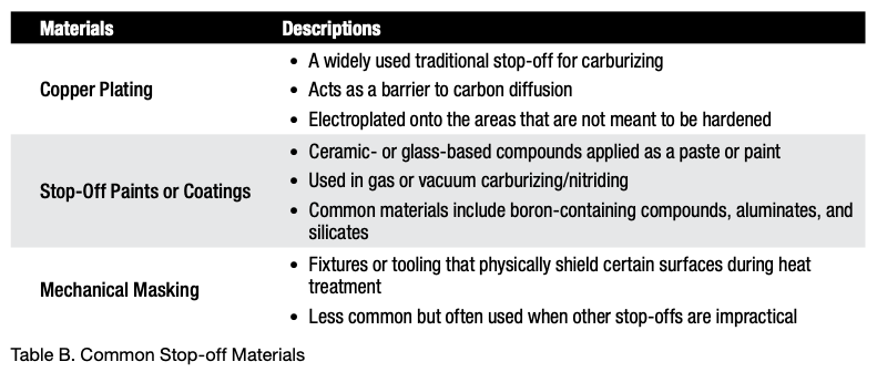
A material that masks the surface of steel and delays or prevents case hardening is called a stop-off or maskant. These materials are applied to specific areas of a steel part to prevent the diffusion of hardening elements (like carbon or nitrogen) into the surface during case hardening processes, such as carburizing, nitriding, or carbonitriding. (See Table B.)

Enriching Gas Additions (Sooting)

During the carburizing or carbonitriding process, it is not uncommon to develop a layer of soot on the surface of the parts, especially if the enriching gas additions begin before the entire load is uniformly up to temperature. In some instances, the amount of soot formation is such that the case depth or uniformity is affected. This is often difficult to diagnose, as the soot layer “washes off” during quenching in a liquid, and the part surfaces come out of the furnace looking reasonably clean.

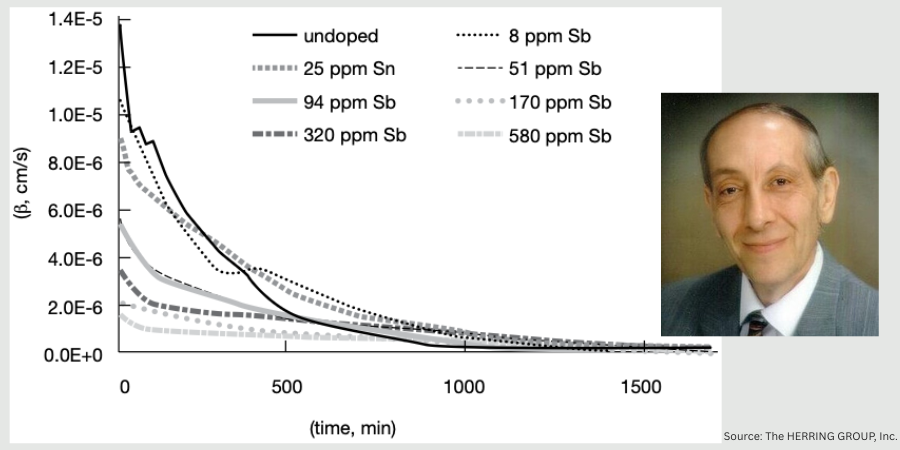
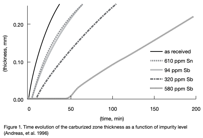
The use of scrap in steelmaking, especially for low alloy case hardening steels can lead to a relatively high level of impurities and tramp elements. At high temperatures these impurities tend to segregate at grain boundaries and migrate toward the surface. This type of segregation can retard case hardening by impeding element (e.g., carbon) transfer. For example, the effects of tin (Sn) and antimony (Sb) on the kinetics of carburization are particularly problematic (Figure 1).

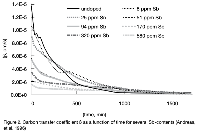
The effect of tramp elements on retardation of carburization can be expressed in the following order (Andreas, et al. 1996), namely Sb > Sn > P > Cu > Pb. To see the effect of one such element, the carbon transfer coefficient (ß) for typical commercial steels is shown as a function of antimony (Sb) content (Figure 2).

In Summary

These are a few of the many causes delaying or preventing case hardening from being effective. There are many others, including alkaline cleaning compounds (in too high a concentration) and even phosphate and other drawing lubricants used in the manufacture of fasteners. Inspection and cleaning of the part surface prior to case hardening will avoid many of these issues. Reviewing material certification sheets for elements known to interfere with case hardening is also an effective way to anticipate problems with case hardening.

References

Herring, Daniel H. 2014. Atmosphere Heat Treatment, Volume 1. Troy, MI: BNP Media.

Herring, Daniel H. 2015. Atmosphere Heat Treatment, Volume 2. Troy, MI: BNP Media.

Ruck, Andreas, Monceau, Daniel, and Grabke, Hans Jürgen. 1996. “Effects of Tramp Elements Cu, P, Pb, Sb, and Sn on the Kinetics of Carburization of Case Hardened Steels.” Steel Research 67 (6): 242–48.

About the Author

Dan Herring
“The Heat Treat Doctor”
The HERRING GROUP, Inc.

Dan Herring has been in the industry for over 50 years and has gained vast experience in fields that include materials science, engineering, metallurgy, new product research, and many other areas. He is the author of six books and over 700 technical articles.

For more information: Contact Dan at dherring@heat-treat-doctor.com.

For more information about Dan’s books: see his page at the Heat Treat Store.


Ask The Heat Treat Doctor®: What Masks the Steel’s Surface in Case Hardening? Read More »

What Is Hydrogen Embrittlement? Part 2

Ask The Heat Treat Doctor® has returned to bring sage advice to Heat Treat Today readers and to answer your questions about heat treating, brazing, sintering, and other types of thermal treatments as well as questions on metallurgy, equipment, and process-related issues.

This informative piece was first released in Heat Treat Today’s October 2025 Ferrous & Nonferrous Heat Treatments/Mill Processing print edition.

In today’s Technical TuesdayDan Herring continues his exploration of what hydrogen embrittlement is by contrasting it with other forms of embrittlement. Learn how to identify these various forms of brittle intergranular failure below!


We continue our discussion from last month concerning hydrogen-assisted cracking (aka hydrogen embrittlement) by looking at closely related phenomena, often mistaken for hydrogen embrittlement. Let’s learn more.

As a brief recap of what we discussed last month, the severity and mode of the hydrogen damage depends on:

  • Source of hydrogen — external (gaseous) or internal (dissolved)
  • Exposure time
  • Temperature and pressure
  • Level of residual and applied stresses
  • Type of alloy and its production method
  • Method of heat treatment
  • Treatment of exposed surfaces (barrier layers, e.g., oxide layers as hydrogen permeation barriers on metals)
  • Final treatment of the metal surface (e.g., galvanic nickel plating)
  • Presence of chemicals that may react with metals (e.g. acidic solutions)
  • Number of discontinuities in the metal

There are, however, several other embrittlement mechanisms that are often mistaken for hydrogen embrittlement and we will explore these here.

Quench Embrittlement

Contact us with your Reader Feedback!

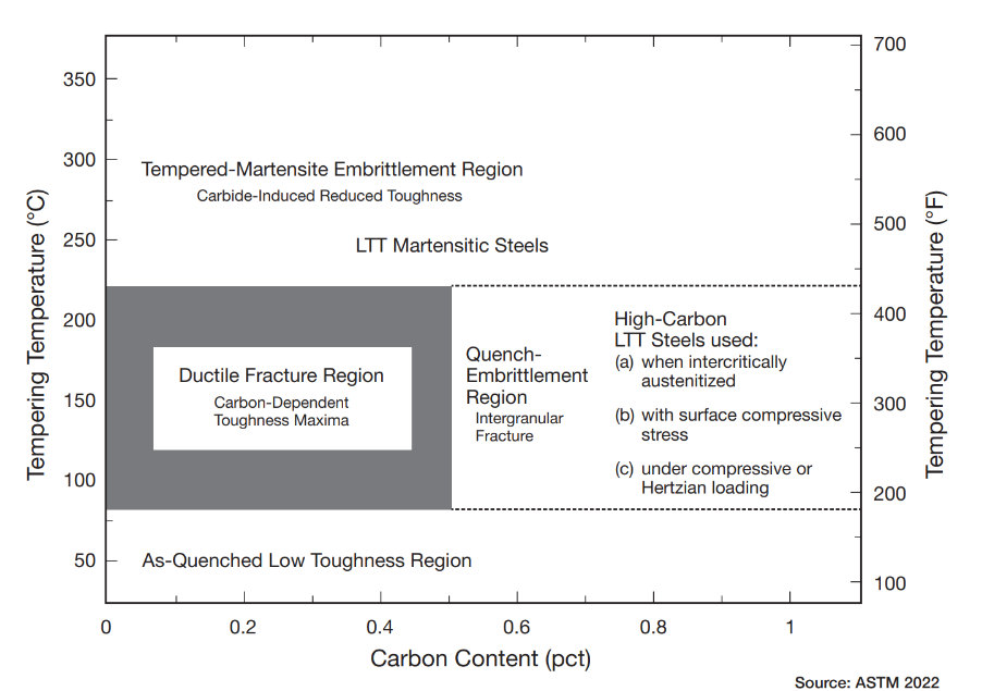
Many high hardenability steels (e.g., 4140, 4340, 52100) are susceptible to a form of brittle intergranular failure from a phenomenon known as quench embrittlement. Under tensile or bending stress, higher carbon steels are susceptible to intergranular fracture in both the as-quenched condition and/or after low temperature tempering — generally considered “safe” from traditional embrittlement. A transition from ductile to intergranular fracture in martensitic steels having greater than 0.5% C can be embrittled even when tempered at low temperatures.

This phenomenon is different from tempered martensite embrittlement (TME) or temper embrittlement (TE), as explained below, as embrittlement occurs before tempering. The issue is exacerbated by the presence of certain embrittling elements (e.g., P, S, As, Sb, Sn, Pb) solely or when their combination reaches a high enough percentage (typically, 0.10%).

Temper Embrittlement

In broad based terms, TE involves a reduction in the normal ductility of a metal due to a physical or chemical change. TE is characterized by reduced impact toughness and occurs in certain quenched and tempered steels and even in ductile irons with susceptible compositions. This form of embrittlement does not typically affect room temperature tensile properties but causes significant reductions in impact toughness and fatigue performance. Although normally associated with tempered martensite, it can also occur if the matrix is tempered to the fully ferritic condition.

Types of Temper Embrittlement

When tempering steel, several types of embrittlement must be avoided. The first type, TME, is an irreversible phenomenon that can occur within 200−400°C (390−750°F). Years ago, it was called “blue brittleness” for the steel’s surface oxidation appearance, but this term is misleading since it can occur at temperatures below the onset of a blue coloration on steel.

Figure 1. Fracture modes in hardened steels

The second type is TE, a reversible phenomenon that occurs when steels are heated in and/or slow cooled through the temperature range of 375−575°C (705−1070°F).

Why Does it Happen?

TME and TE are examples of intergranular embrittlement. A common factor in such failures is the presence of elements that segregate to the grain boundaries. The chemical reaction rate or kinetics of segregation are such that they exhibit “C” curve behavior in the 350−550°C (660−1020°F) range; in other words, segregation does not occur uniformly. Both types of embrittlement are in part related to grain-boundary segregation of impurity elements (e.g., As, P, Sb, Sn), and both develop during thermal processing after austenitizing and quenching to martensite, usually indicated by an upward shift in ductile-to-brittle transition temperature.

TME is thought to result from the combined effects of cementite precipitation on prior-austenite grain boundaries or interlath boundaries and the segregation of impurities at prior-austenite grain boundaries. By contrast, TE is thought to be caused by the formation of carbides on decomposition of martensite, in particular, precipitation of carbides in the form of films at grain boundaries. At higher temperatures of tempering, this film disappears and cannot be restored on repeated heating at 250−400°C (480−750°F).

Which Steels Are Affected?

All steels are susceptible, so the real question becomes how susceptible and what factors affect that susceptibility. For example, while plain carbon steels may contain some of the same impurity elements that will cause the embrittlement phenomenon to occur in other steels, the segregation of these elements is often enhanced by or caused by the presence of other alloying elements in substantial quantities. As a result, alloy steels, in general, have more susceptibility than carbon steels.

It is important to understand that the degree of embrittlement is affected by the prior austenite grain size and hardness. So, if we are dealing with a fine-grained plain carbon steel of low hardness, it may not experience embrittlement symptoms despite its phosphorous content, whereas a more highly alloyed Cr-Ni steel used at higher hardness is more susceptible to its impurity content.

Widely used alloying elements, such as chromium, nickel, and manganese, tend to promote TE with the highest embrittlement effect observed in Cr-Ni and Cr-Mn steels. Small additions of molybdenum (0.2-0.3%) can diminish TE, while greater additions enhance the effect. TE can be prevented by keeping silicon and phosphorus levels as low as possible, adding up to 0.15% molybdenum and avoiding the embrittlement heat treating conditions.

Susceptibility also depends on impurity control and here is where the steelmaking process is critical. For example, in plain carbon and Cr-Mo steels (those with no Ni) where phosphorous is the most impactful embrittlement element, the percentage can be controlled by the steelmaking process. In steels that contain significant amounts of nickel, antimony and tin are more potent embrittlement elements. Phosphorous has an effect but not as large as it has in plain carbon and Cr-Mo steels. It should be noted, however, that antimony and tin in plain carbon steels can cause other hot working issues.

How Can We Correct It?

TME is irreversible, and its effects are permanent. By contrast, the effects of TE can be reversed. This is done by re-tempering above the critical temperature of 575°C (1070°F) then cooling rapidly. Impact toughness can be restored. If necessary, this process can be repeated.

A Simple Example

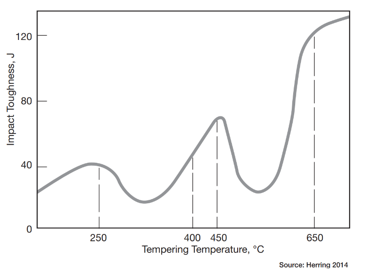
Alloy steel, which is susceptible to TE, will exhibit a relationship such as shown on Figure 2. Note that the impact toughness of quenched steel after tempering at 200−400°C (390−750°F) is lower than that obtained on tempering at temperatures below 200°C (390ºF). If brittle steel tempered in this range is heated above 400°C (750ºF) and transformed into a tough state, a second tempering at 250−400°C cannot return it to the brittle state. The rate of cooling from the tempering temperature range of 250−400°C has no effect on impact toughness.

Figure 2. Effect of temperature on impact toughness

The susceptibility of a given steel to TE depends on a number of factors, including grain size, hardness, steel grade, and the impurity control in the steelmaking process itself. Remember, not all steels and not all steelmaking processes are equivalent.

A heat treaters we must avoid the temptation to temper to a given hardness value without understanding the consequences of our actions. Since we do not have a simple embrittlement test that can be used on the shop floor, we must understand the phenomenon and question specifications that put us into TE ranges.

In Summary

The insidious nature of hydrogen embrittlement continues to cause concern and product failures during processing and during service, but as explained above, there are other heat treatment operations that can result in embrittlement. All of these and others (e.g., aluminum nitride embrittlement, overheating during forging, hot shortness) are responsible for many serious and in some instances catastrophic failures leading to injury or damage. All must be avoided.

References

ASTM International. 2022. ASTM B850-98 (Reapproved 2022): Standard Guide for Treatments of Steel for Reducing the Risk of Hydrogen Embrittlement. West Conshohocken, PA: ASTM International. https://www.astm.org.

Herring, D. H. 2014–2015. Atmosphere Heat Treatment, vols. 1–2. Troy, MI: BNP Media.

Herring, D. H. 2006. “The Embrittlement Phenomena in Hardened & Tempered Steels.” Industrial Heating, October.

Herring, D. H. 2004. “A Heat Treater’s Guide to Hydrogen Embrittlement.” Industrial Heating, October.

About the Author

Dan Herring
“The Heat Treat Doctor”
The HERRING GROUP, Inc.

Dan Herring has been in the industry for over 50 years and has gained vast experience in fields that include materials science, engineering, metallurgy, new product research, and many other areas. He is the author of six books and over 700 technical articles.

For more information: Contact Dan at dherring@heat-treat-doctor.com.

For more information about Dan’s books: see his page at the Heat Treat Store.
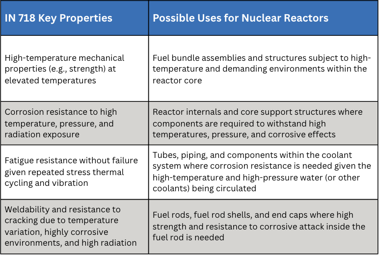
What Is Hydrogen Embrittlement? Part 2 Read More »

What Is Hydrogen Embrittlement? Part 1

Ask the Heat Treat Doctor® has returned to bring sage advice to Heat Treat Today readers and to answer your questions about heat treating, brazing, sintering, and other types of thermal treatments as well as questions on metallurgy, equipment, and process-related issues.

This informative piece was first released in Heat Treat Today’s September 2025 People of Heat Treat print edition.

If you’ve ever experience internal cracking, surface blistering, loss of ductility, or high pressure hydrogen attack, today’s Technical Tuesday might contain just the information you need to avoid it. Read below to learn from Dan Herring as he addresses what hydrogen embrittlement is, how to avoid it, and what solutions should not be pursued in order to fix it.


The other night, The Doctor decided to relax and watch a rather whimsical movie, The Great Race (1965), directed by Blake Edwards, who is perhaps better known for directing Breakfast at Tiffany’s and The Pink Panther. It is most memorable not for the actors, nor the plot, but for the infamous pie fight involving over 4,000 pies in a scene that took more than five days to film but lasted only four minutes on the big screen. Not one actor was spared the embarrassment of being hit by (multiple) pies in the face!

So, what does THIS have to do with heat treatment, you ask? Well, try as he may to believe the subject has been explained well in the past, The Doctor has been inundated recently with questions about hydrogen embrittlement (aka hydrogen-assisted cracking). Let’s learn more.

What Is It?

Hydrogen-assisted cracking (HAC) is an embrittlement phenomenon responsible for a surprising number of part cracking issues in heat treatment and is found to be the cause of many delayed field failures, especially if the components undergo secondary operations such as plating (Figure 1).

Figure 1. Tin-plated electrolytic tough pitch (ETP) copper battery lugs embrittled during oxy-acetylene brazing

How Does Hydrogen Get In?

It is generally agreed that hydrogen in atomic form will enter and diffuse through a metal surface at elevated or ambient temperatures. The simple rule to remember about hydrogen is fast in, slow out. Once absorbed, atomic hydrogen often combines to form molecular hydrogen or other hydrogen molecules (e.g., methane). As these are too large to diffuse through the metal, pressure builds at crystallographic defects (e.g., dislocations and vacancies) and/or discontinuities (e.g., voids, laps/seams, inclusion/matrix interfaces) causing minute cracks to form. Whether this absorbed hydrogen causes immediate cracking or not is a complex interaction of material strength, external stresses, and temperature.

Figure 2. Intergranular fracture of a plated component (SEM image)

Most heat treaters associate hydrogen embrittlement with the plating process and the lack of a proper bake-out cycle. However, there are many other sources of hydrogen, including heat treating atmospheres; breakdown of organic lubricants left on parts; the steelmaking process (e.g., electric arc melting of damp scrap); dissociation of high-pressure hydrogen gas; arc welding (with damp electrodes); grinding (in a wet environment); and the end-use environment.

Parts undergoing electrochemical surface treatments, such as etching, pickling, phosphate coating, corrosion removal, paint stripping, and electroplating, are especially susceptible (Figure 2).

What Is The Nature and Effect of Hydrogen Attack?

Although the precise mechanism(s) is the subject of active investigation (Figure 3), the reality is that components fail due to HAC. It is generally believed that all steels above 30 HRC are vulnerable, as are materials such as copper, titanium and titanium alloys, nickel and nickel alloys, and the like. See Table A below for examples of hydrogen damage and ways to avoid it.

Figure 3a and 3b. Hydrogen embrittlement mechanism models

Since a metallurgical interaction occurs between atomic hydrogen and the atomic structure, the ability of the material to elastically deform or stretch under load is inhibited. Therefore, it becomes “brittle” under applied stress or load. As a result, the metal will break or fracture at a much lower load or stress levels than anticipated by designers. Since failures can be of a delayed nature, hydrogen embrittlement is insidious.

Table A. Problems with hydrogen damage and ways to avoid them

In general, as the strength of the steel goes up, so does its susceptibility to hydrogen embrittlement. High strength steel, such as quenched and tempered steels (e.g., 4140, 4340), or precipitation hardened steels are particularly vulnerable. It is often called the Achilles heel of high strength ferrous steels and alloys.

Nonferrous Materials and Hydrogen Embrittlement

Nonferrous materials are also not immune to attack. Tough-pitch coppers and even oxygen-free coppers are subject to a loss of (tensile) ductility when exposed to reducing atmospheres. Bright annealing in hydrogen bearing furnace atmospheres or torch/furnace brazing are typical processes that can induce embrittlement of these materials.

In copper, the process involves diffusion and subsequent reduction of cuprous oxide (Cu₂O) to produce water vapor and pure copper. An embrittled copper often can be identified by a characteristic surface blistering resulting from expansion of water vapor in voids near the surface. Purchasing oxygen-free copper is no guarantee against the occurrence of hydrogen embrittlement, but the degree of embrittlement will depend on the amount of oxygen present. For example, CDA 101 (oxygen free electronic) allows up to 5 ppm oxygen while CDA 102 (OFHC) permits up to 10 ppm. A simple bend test is often used to detect the presence of hydrogen embrittlement. Metallographic techniques can also be used to look at the near surface and for the presence of voids at grain boundaries.

Are Low Hydrogen Concentrations Also Problematic?

Of concern today is embrittlement from very small quantities of hydrogen where traditional loss-of-ductility bend tests cannot detect the condition. This atomic level embrittlement manifests itself at levels as low as 10 ppm of hydrogen — in certain plating applications it has been reported that 1 ppm of hydrogen is problematic! Although difficult to comprehend, numerous documented cases of embrittlement failures with hydrogen levels this low are known.

This type of embrittlement occurs when hydrogen is concentrated or absorbed in certain areas of metallurgical instability. This concentrating action occurs via either residual or applied stress, which tends to “sweep” through the atomic structure, moving the infiltrated hydrogen atoms along with it. These concentrated areas of atomic hydrogen can coalesce into molecular type hydrogen, resulting in the formation of high localized partial pressures of the actual gas.

How Does Hydrogen Get Out?

Hydrogen absorption need not be a permanent condition. If cracking does not occur and the environmental conditions are changed so that no hydrogen is generated on the surface of the metal, the hydrogen can re-diffuse out of the steel, and ductility is restored. Performing an embrittlement relief cycle, or hydrogen bake-out cycle (the term “bake-out” is misleading as the process involves both inward diffusion and outgassing), is a powerful method in eliminating hydrogen before damage can occur. Key variables are temperature, time at temperature, and concentration gradient (atom movement).

Contact us with your Reader Feedback!

Electroplating, for example, provides a source of hydrogen during the cleaning and pickling cycles, but by far the most significant source is cathodic inefficiency. To eliminate concerns, bake-out cycles and recommended temperatures/times are shown in ASTM B850-98 (latest revision) as a function of steel tensile strength (see Table 1 of the specification). However, in this writer’s eyes, a “bake-out” cycle of at least 24 hours at temperature is required for the effective elimination of hydrogen as a concern regardless of the tensile strength of the material. Also, caution should be exhibited to prevent over-tempering or softening of the steel, especially on a carburized, or induction hardened part.

Next time we will talk about quench and temper embrittlement, as well as embrittlement due to overheating during forging, all of which are often mistaken for hydrogen embrittlement.

References

ASTM International. 2022. ASTM B850-98 (Reapproved 2022), Standard Guide for Treatments of Steel for Reducing the Risk of Hydrogen Embrittlement. West Conshohocken, PA: ASTM International. https://www.astm.org.

Herring, D. H. 2004. “A Heat Treater’s Guide to Hydrogen Embrittlement.” Industrial Heating, October.

Herring, D. H. 2006. “The Embrittlement Phenomena in Hardened & Tempered Steels.” Industrial Heating, October.

Herring, D. H. 2014–2015. Atmosphere Heat Treatment, Volumes I & II. Troy, MI: BNP Media.

Krause, George. 2005. Steels: Processing, Structure, and Performance. Materials Park, OH: ASM International.

About the Author

Dan Herring
“The Heat Treat Doctor”
The HERRING GROUP, Inc.

Dan Herring has been in the industry for over 50 years and has gained vast experience in fields that include materials science, engineering, metallurgy, new product research, and many other areas. He is the author of six books and over 700 technical articles.

For more information: Contact Dan at dherring@heat-treat-doctor.com.

For more information about Dan’s books: see his page at the Heat Treat Store.
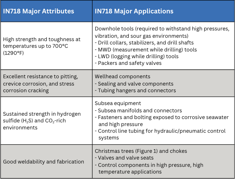

Find Heat Treating Products And Services When You Search On Heat Treat Buyers Guide.Com


What Is Hydrogen Embrittlement? Part 1 Read More »

What Is Quench Cracking and How Can It Be Prevented?

The Heat Treat Doctor® has returned to offer sage advice to Heat Treat Today readers and to answer your questions about heat treating, brazing, sintering, and other types of thermal treatments as well as questions on metallurgy, equipment, and process-related issues.

This informative piece was first released in Heat Treat Today’s August 2025 Automotive Heat Treating print edition.

Quench cracking during heat treatment can turn expensive components into scrap metal in seconds. In today’s Technical Tuesday article, Dan Herring (The Heat Treat Doctor®) explores more about the underlying mechanisms and proper preventative measures to save you time, money, and ensure reliable part performance.


As a young heat treater, I learned first-hand about quench cracking while running various dies for our tool and die shop — and succeeded in cracking all of them! I have never forgotten the foreman’s (rather animated) critique of my heat treating abilities. Quench cracking can be a significant problem for heat treaters, its potential consequences ranging from costly rework to premature failure in the field. Let’s learn more.

We must not only understand the mechanisms involved but also take proactive steps to avoid it. This includes careful consideration of such items as:

  • Material (e.g., chemistry, hardenability, form, mill processing)
  • Component part design (e.g., sharp radii, thin and thick sections next to one another)
  • Manufacturing processing steps (e.g., the effect of stress relief after rough machining)
  • Part loading (e.g., part orientation in relation to the quench, fixturing, total load weight)
  • Equipment choice (i.e., limitations and capabilities)
  • Quench medium (e.g., type, agitation, flow characteristics, temperature, temperature rise)
  • Process parameters (e.g., ramp rates, atmospheres, vacuum levels)

The Heat Treatment Challenge

Quench cracking primarily occurs during the hardening process, typically when materials are rapidly cooled via quenching. Since the cooling process introduces internal stresses within the material, it can result in crack formation. These stresses are a result of the rapid transformation of the material’s microstructure, most notably when transforming to martensite, a very hard, brittle structure.

Figure 1. Quench crack in a 4140 axle shaft

Mechanisms Involved

Failure mechanisms related to quench cracking include the following seven factors.

Material Imperfections

As material is heated, thermally induced stresses can cause existing surface or subsurface defects, such as inclusions, laps, and seams. These defects act as stress risers to open and propagate into cracks. Once a defect reaches “critical flaw size” — the smallest flaw that can lead to failure under expected operational stress levels — crack propagation will begin and lead to part failure.

Rapid or uneven heating only exacerbates this issue, especially when a material undergoes phase transformations that introduce volumetric changes.

Stress Risers

Sharp corners, steep edges around holes, and even grooves in parts create stress concentration points where quench cracking is most likely to occur. These features also result in localized heating and cooling, causing differential stresses that can initiate cracks.

  • The sharp edges of a part, for instance, cool much faster than the rest of the material, leading to a high risk of cracking.
  • Proper design modifications, such as adding radii to sharp corners, can reduce the likelihood of stress concentrations.

Rapid Cooling and Phase Transformation

The transformation from austenite to martensite during quenching is a key contributor to internal stresses. The rate at which the material cools can greatly influence these stresses. If cooling is too rapid or if tempering is delayed, the material can become overly brittle, leading to quench cracking.

Improper Heating and Overheating

Overheating during the austenitizing process can lead to coarse-grained structures that are more prone to quench cracking. Coarse grains increase the depth of hardening but reduce the material’s resistance to cracking. It is critical to avoid temperature overshoot, high ramp rates, and excessively long dwell times when heating.

Inadequate Quenching Methods

The choice of quench medium (brine, water, oil, polymer, high pressure gas, etc.) can also contribute to quench cracking. Overly aggressive quenchants may create excessive thermal stresses.

Improper Fixturing

The way parts are positioned during quenching can create problems. If parts are bunched together in a basket, uneven cooling rates will occur, with parts on the edges cooling faster than those in the center. This can lead to differential stresses and increase the risk of cracking.

Delays Between Quenching and Tempering

Quenching produces high residual stresses in the material, and if parts are not tempered soon after quenching, these stresses can lead to cracking. For materials with high hardenability, such as 4340 steel, immediate tempering (usually within 15 minutes of quenching) is critical to prevent in-service failure.

Understanding Fracture Mechanics

Contact us with your Reader Feedback!

Understanding these mechanisms is critically important. A material’s fracture toughness, which is the ability to resist crack growth, is defined by the stress intensity factor (KIC). This value varies based on the material’s properties and the size and geometry of the crack. The important point to remember is that when the applied stress reaches a critical threshold, cracks begin to propagate (literally at the speed of sound), leading to catastrophic failure.

Digging a bit deeper, there are three primary modes of fracture:

  • Tensile (Mode I): Fracture caused by tensile stress at the crack tip.
  • Sliding (Mode II): Fracture caused by shear stress that causes the two sides of the crack to slide.
  • Tearing (Mode III): Fracture caused by shear forces in a direction perpendicular to the crack plane.

Preventive Measures

Several strategies can be employed to minimize the risk of quench cracking during heat treatment. They broadly fall into the following categories.

Material Selection

Choosing the right material for the job is essential. Many designers select materials with high hardenability, forgetting that they can be prone to cracking. Additionally, one should take special care with materials that have high carbon content or are heavily alloyed.

Design Considerations

Ensure that part designs minimize stress risers. Avoid sharp corners and incorporate radii where necessary. Proper design can reduce the likelihood of cracks forming at critical locations.

Improved Manufacturing Practices

Proper stock removal during machining and addressing surface imperfections before heat treatment can prevent the initiation of cracks. Machining should aim to eliminate any seams or inclusions that might act as nucleation sites for cracks. Stress relief after rough machining is almost always a good idea.

Control of Heat Treatment Parameters

Maintain tight control over the heating and quenching processes to ensure uniformity. Avoid overheating and try to ensure that the part enters the quench medium in the best possible orientation to reduce the likelihood of creating differential cooling rates.

Figure 2. Quench crack due to a combination of rapid heating, overheating and improper polymer quench medium concentration in a motor shaft (50x, as polished)

Quenching Media

Select the appropriate quenching medium based on the material, part geometry, and load. Less aggressive quenchants or minimizing time in the quench should be considered for materials with moderate to high hardenability.

Post-Quench Tempering

Temper parts as soon as practical after quenching to avoid concerns with internal stresses. High-hardness materials should be tempered immediately to prevent quench cracking.

Quench Cracking in Other Materials

Quench cracking is not exclusive to steel. Other materials, such as nickel and cobalt superalloys, can also experience cracking due to similar mechanisms. In these materials, the phenomena are often referred to as “fire cracking,” “strain-age cracking,” or “stress cracking.” As with steel, cracks in these materials are often linked to high residual tensile stresses on the surface and the presence of stress raisers. Strategies, such as shot peening, redesigning part geometries, and improving surface finishes, can help mitigate cracking in superalloys.

Summing Up

Quench cracking represents a significant challenge in heat treatment, but by understanding its underlying mechanisms, heat treaters and engineers can take steps to mitigate the risk. Material selection, part design, proper heat treatment procedures, and timely tempering are all critical factors in preventing quench cracking and ensuring the integrity of components. A proactive approach to addressing flaws and stress concentrators combined with careful attention to detail in every stage of the manufacturing and heat treatment process can greatly reduce the likelihood of failure and contribute to the long-term success of heat treated products.

References

Herring, Daniel H. 2012. “Quench Cracking.” Industrial Heating, April.

Herring, Daniel H. 2015. Atmosphere Heat Treatment, Volume 2. BNP Media.

Johnson, D. D. 2005. “Thermal and Mechanical Behavior of Materials.” University of Illinois.

Klarstrom, Dwaine L. 1996. “Heat Treat Cracking of Superalloys.” Advanced Materials and Processes, April.

Krauss, George. 2005. Steels: Processing, Structure and Performance. ASM International.


About the Author

Dan Herring
“The Heat Treat Doctor”
The HERRING GROUP, Inc.

Dan Herring has been in the industry for over 50 years and has gained vast experience in fields that include materials science, engineering, metallurgy, new product research, and many other areas. He is the author of six books and over 700 technical articles.

For more information: Contact Dan at dherring@heat-treat-doctor.com.

For more information about Dan’s books: see his page at the Heat Treat Store.
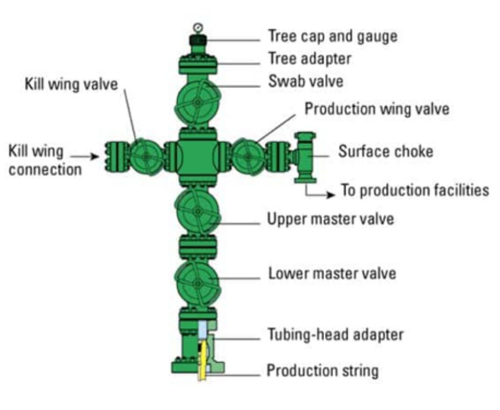

Find Heat Treating Products And Services When You Search On Heat Treat Buyers Guide.Com


What Is Quench Cracking and How Can It Be Prevented? Read More »

Ask The Heat Treat Doctor®: What Are the Differences Between Intergranular Oxidation (IGO) and Intergranular Attack (IGA)? 

The Heat Treat Doctor® has returned to offer sage advice to Heat Treat Today readers and to answer your questions about heat treating, brazing, sintering, and other types of thermal treatments as well as questions on metallurgy, equipment, and process-related issues.

Today’s Technical Tuesday is a pre-release foretaste of the great content you can find in Heat Treat Today’s July 2025 Super Brands print edition.

Heat treaters and metallurgists speak a language unique to our industry and it can be confusing at times; terms like intergranular oxidation (IGO) and intergranular attack (IGA) are good examples, as these terms are often (incorrectly) used interchangeably. While these two phenomena sound similar, they have distinct mechanisms, causes, and impacts on material properties. Expert Dan Herring explores them more below.


What is IGO?  

Contact us with your Reader Feedback!

IGO is a process by which oxygen preferentially reacts with the metal surface at the grain boundaries, creating oxides (Figure 1). It is not uncommon, for example, to see IGO present after a hardening process run in an Endothermic or nitrogen/methanol atmosphere. As parts are heated to austenitizing temperature, oxygen present due to minute air leaks or produced during the various chemical reactions with the atmosphere results in IGO. The grain boundaries are highly susceptible to oxidation because these are areas where different crystallographic grains meet and are areas of high energy due to the atomic mismatch and disruption of the regular crystal lattice structure.  

Figure 1. Intergranular oxidation (IGO) along the surface of a heat treated chromium steel component. 1000X – As Polished
Source: The HERRING GROUP, Inc.

What is IGA?  

Figure 2. Intergranular attack (IGA) along the surface of a martensitic steel component caused by excessive submersion time in a citric acid solution. 1000X – As Polished
Source: The HERRING GROUP, Inc.

IGA, on the other hand, is a broader term that refers to a corrosion phenomenon (aka chemical attack) that specifically targets the grain boundaries of a material. Unlike IGO, intergranular attack (Figure 2) is not limited to oxidation reactions but encompasses a variety of forms of attack involving such things as the formation of precipitates, the dissolution of material at grain boundaries, or the creation of corrosion cracks. Common forms of IGA include stress corrosion cracking (SCC) or sensitization in stainless steel. 

In stainless steels, IGA is often triggered by high-temperature environments, usually in the range of 840º – 1560ºF (450 – 850°C) where carbon reacts with chromium to form chromium carbides at the grain boundaries, thus reducing the material’s resistance to corrosion in localized regions. In other alloys, factors like pH, chloride concentration, and temperature can lead to IGA. 

Both IGO and IGA weaken the material’s structural integrity or lead to embrittlement compromising the material’s integrity.

Effect on Material Properties 

The main effect of intergranular oxidation is the degradation of the mechanical properties, particularly a reduction in both ductility and toughness. As oxidation progresses along the grain boundaries, the material tends to become brittle, which can lead to premature failure under certain types of stress or thermal cycling. IGO often appears visually as a uniform discoloration or thin oxide layer on the surface. Surface pitting is not typically observed. 

By contrast, IGA often appears as visible cracks, pits, or localized regions where the metal has been attacked (along the grain boundaries). This leads to a reduction in mechanical strength and can lead to SCC under certain circumstances. IGA can severely compromise the integrity of the material, particularly in critical applications like pipelines, pressure vessels, and nuclear reactors.

Materials Involved 

IGO is most commonly observed in steel, aluminum, titanium, and nickel-based alloys, not only during heat treatment but when exposed to oxidizing environments in high-temperature applications, which also result in degradation and loss of material strength and other properties. 

IGA tends to be more prevalent in stainless steels, corrosion-resistant alloys, and aluminum alloys. It is especially noticeable in alloys that are susceptible to sensitization (where chromium carbides precipitate at grain boundaries), leading to localized corrosion and cracks. Alloys that form a passivating oxide layer can be more susceptible to IGA if that layer is disrupted. 

Principal Concerns 

The main concern with intergranular oxidation is material embrittlement, leading to reduced ductility and potential failure under mechanical stress, especially in high-temperature applications. It can also affect the integrity of critical components, such as those used in aerospace or power generation industries. 

By contrast, the primary impact of intergranular attack is loss of material strength, leading to structural failure, often without any clear outward signs (e.g., under chloride-induced SCC). It is more likely to cause immediate failure or a dramatic loss in performance, especially in structures exposed to corrosive environments. 

How to Detect IGO and IGA 

IGO is typically detected by examining the material’s surface using optical or scanning electron microscopy (SEM). Non-destructive techniques, such as X-ray diffraction (XRD), can also be used. 

IGA is usually detected through methods like microstructural examination, electrochemical testing, or failure analysis. Techniques, such as SEM or energy-dispersive X-ray spectroscopy (EDS), can be used to examine the grain boundary regions for signs of corrosion. 

How to Avoid IGO and IGA 

IGO can be avoided by one or more of the following: 

  • Environmental control: Making sure the heat treat furnace has no leaks, reducing oxygen partial pressure or controlling the furnace atmosphere in high-temperature heat treat operations. 
  • Alloy design: The use of materials with stable oxide-forming elements (e.g., chromium, titanium and aluminum) or alloys with high resistance to oxidation (e.g., nickel-based superalloys). 
  • Temperature control: Maintaining lower process temperatures and shorter times where possible to prevent oxidation at the grain boundaries. 
  • Coatings and surface treatments: Application of protective coatings, such as copper plating, post-heat treatment aluminizing, or chrome plating, to reduce oxygen interaction with the grain boundaries during service.  

IGA can be avoided by one or more of the following: 

  • Environmental control: Reducing exposure to aggressive chemicals (e.g., chloride ions) by maintaining proper pH levels or using inhibitors in post-cleaning processes. 
  • Proper alloy selection: Selecting materials resistant to intergranular corrosion (e.g., low carbon “L” grades of stainless steel or alloys with improved grain boundary stability). 
  • Heat treatment: Avoiding sensitization of stainless steel by proper heat treatment methods that prevent the formation of chromium carbides at grain boundaries. 
  • Stress relief: Reducing the likelihood of stress corrosion cracking by managing internal stresses during manufacturing and in-service conditions. 

Key Differences 

The differences between these phenomena are summarized in Table 1. 

Table 1. Key differences between IGO and IGA
Source: The HERRING GROUP, Inc.

Summing Up 

While both IGO and IGA involve attack at the grain boundaries, they differ in their mechanisms, causes, and effects. From a heat treater’s perspective, IGO most often results at high temperature in oxygen-bearing furnace atmospheres, while IGA often results from pre- or post-heat treatment processing (cleaning, passivation, plating, etc.). Proper material selection, furnace and environmental control, awareness of what can happen, and inspection for these effects are key to preventing them from occurring.  

References

Roberge, Pierre R., Corrosion Engineering: Principles and Practice, Mc-Graw Hill LLC, 2008.  

Stene, Einar S., Fundamentals of Corrosion: Mechanisms, Causes, and Monitoring.  

Schweitzer, Philip A., Fundamentals of Corrosion: Mechanisms, Causes and Preventative Methods, CRC Press, 2009. 

About the Author

Dan Herring
“The Heat Treat Doctor”
The HERRING GROUP, Inc.

Dan Herring has been in the industry for over 50 years and has gained vast experience in fields that include materials science, engineering, metallurgy, new product research, and many other areas. He is the author of six books and over 700 technical articles.

For more information: Contact Dan Herring at dherring@heat-treat-doctor.com.

For more information about Dan’s books: see his page at the Heat Treat Store.
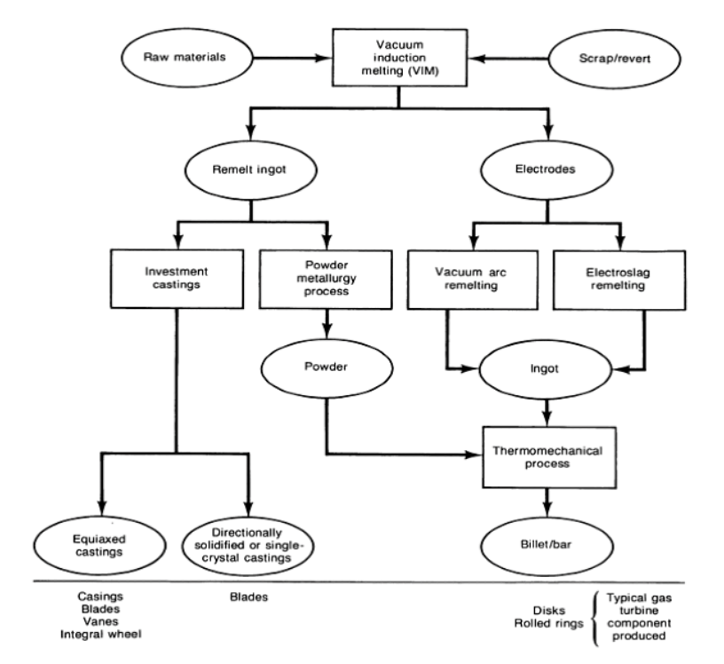

Find Heat Treating Products And Services When You Search On Heat Treat Buyers Guide.Com


Ask The Heat Treat Doctor®: What Are the Differences Between Intergranular Oxidation (IGO) and Intergranular Attack (IGA)?  Read More »