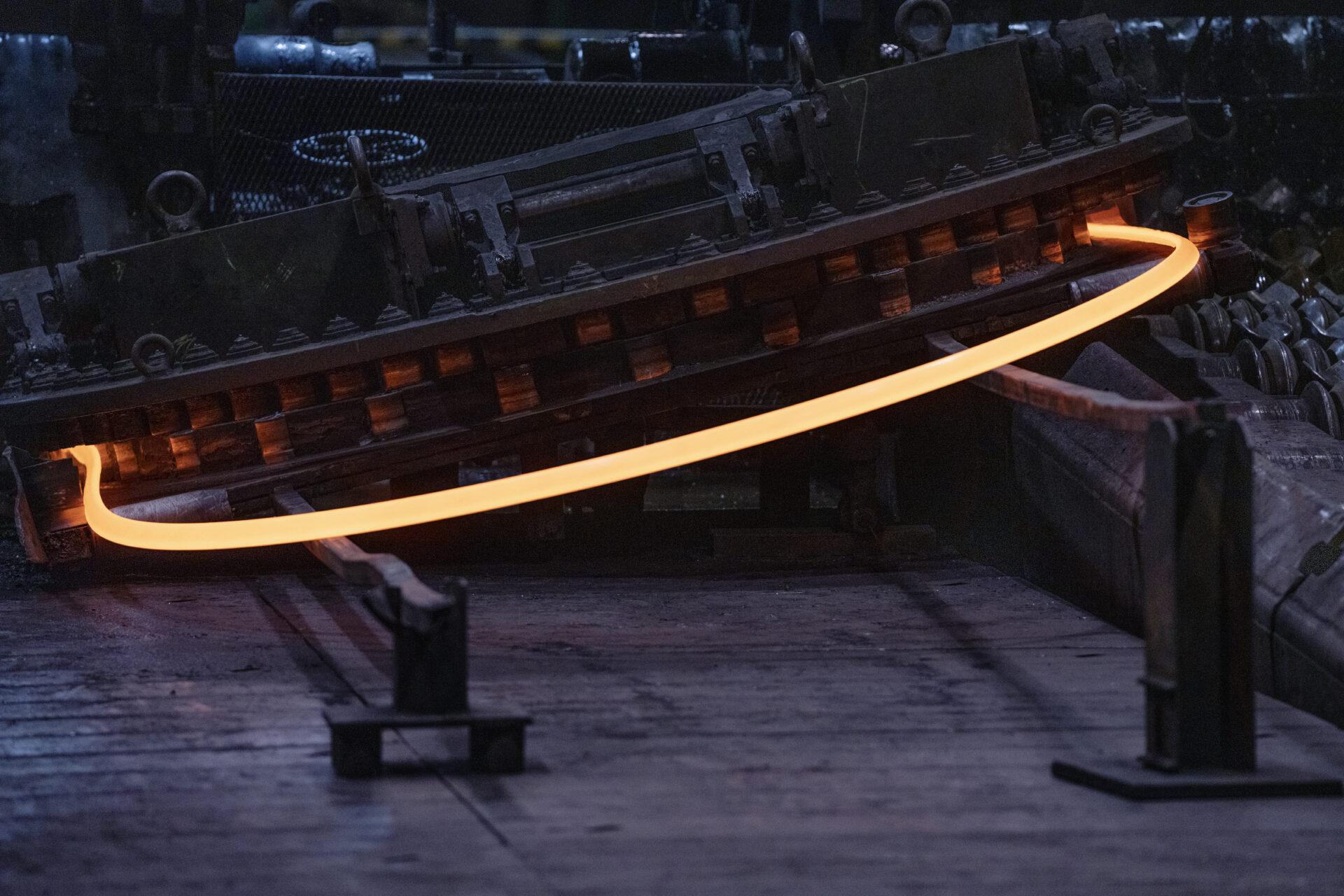
HIP Technologies Will Evolve Alongside Industry Growth
Hot isostatic pressing (HIP) is becoming essential to producing stronger, more reliable parts in aerospace, medical, and energy manufacturing. As these industries scale up, HIP technology is evolving to meet new size, performance, and sustainability demands. This Technical Tuesday installment explores the expanding interest and investment in HIP and how industry innovators are tackling challenges like large-scale systems, long cycle times, and surface cleanliness to unlock HIP’s full potential.
This informative piece was first released in Heat Treat Today’s December 2025 Medical & Energy Heat Treat print edition.
As a manufacturing process that enhances the mechanical properties of metal, ceramic, and plastic materials by uniformly applying high temperature and high pressure, hot isostatic pressing (HIP) techniques are essential when manufacturing high-performance parts for aerospace, energy and other industries. And, as these industries are poised for growth, the HIP market is expected to evolve alongside them. However, HIP industry challenges must be addressed by modern solutions before this advanced manufacturing process sees widespread implementation across these industries.
Still, significant growth is anticipated for the HIP industry over the next five years. A recent report by Verified Market Research (2025), Hot Isostatic Pressing Service Market Size and Forecast, states that the HIP service market size was valued at $2.25 billion in 2023 and is projected to reach over $35 billion by 2030.
According to the report, HIP technology drivers include the need for the development of more advanced materials and components in aerospace, defense, automotive, energy, and medical, where there are high standards for performance, reliability, and robustness. HIP processes, which eliminate internal flaws, porosity, and residual stresses, aid in the production of mission-critical parts in these industries.
For example, HIP can be used to increase the density of materials, remove flaws, and improve mechanical qualities of components, or to combine porous materials while enhancing microstructures to produce lightweight components for industries with energy efficiency initiatives.
HIP also serves as a post-process treatment to enhance the mechanical integrity of complex and high-performance parts made via additive manufacturing (AM) for use in critical applications. In addition, HIP supports the near-net shape manufacturing process as it increases the density and mechanical characteristics of near-net formed parts and increases the efficiency of the near-net shape process.
Aerospace and Energy Sectors Drive Interest and Investment in HIP

Vice President
American Isostatic Presses, Inc.

Applications Engineer
Quintus Technologies
Doug Glenn, publisher of Heat Treat Today, spoke with various leaders in HIP sphere, including Chad Beamer, Cliff Orcutt, and Soumya Nag in early 2025.
Chad Beamer, applications engineer with Quintus, states that much of the interest and investment in HIP is driven by aerospace and energy: “In countries where there is investment in the supply chains for these sectors, there’s a good chance there’s going to be treatment equipment, including HIP, that supports the metallic structures and components they demand.”
The primary driver for interest in further development of HIP technologies is the need for high-performance components for use in the aerospace industry, according to Cliff Orcutt, vice president of American Isostatic Presses, Inc. (API). “Aerospace requires HIP technology to make parts,” Orcutt says, “In other industries you may be able to make parts with forging and other methods, but in aerospace technical requirements, HIP is likely part of the bill of materials.” This is especially true of larger aerospace castings — such as those over 60 inches, he says.
Additionally, recently developed guidelines are expected to help standardize the use of HIP technology in Ti-6A1-4V parts used in aerospace and other industries, according to Beamer. The newly released standard, SAE AMS7028, sets the benchmark for HIP of Ti-6A1-4V parts made via laser powder bed fusion (PBF-LB). The standard defines HIP cycle requirements, surface condition expectations, microstructure and density targets, and mechanical performance standards.
Ti-6Al-4V is ideal for the aerospace industry, where it is used for parts such as aircraft frames, landing gear components, fuselage components, and engine parts, due to its lightweight, high strength, corrosion resistance, and ability to be used in a wide operating temperature range.
According to Quintus, this standard is important because it brings the treatment industry one step closer to ensuring material integrity and repeatable performance in mission-critical applications in aerospace and other industries.
The energy sector is also interested in HIP technology for high-performing, large-scale parts and components across a range of energy-related applications. The U.S. Department of Energy (DOE) is showing significant interest in HIP and powder metallurgy HIP (PM-HIP) technologies and is working toward finding new applications for the process, which the DOE calls “an established, yet, in-flux technology.”
For reference, PM-HIP processes place metal powder into a mold or capsule and expose it to high temperature and high pressure so it fuses into a dense metal component capable of withstanding challenging conditions in difficult applications.
According to the DOE, PM-HIP may find application in the manufacture of near-net shape, complex and large-scale components for small modular reactor (SMR) construction because the process (U.S. Nuclear Regulatory Commission 2022) can help reduce the costs of materials and machining, eliminate the need for welds in some applications, and provide an alternate supply route and shorter turn-around time at a cost point that is equivalent to forging.
For example, there are certain large pieces for the small modular reactors, such as the top dome and the container itself, that could be made from powder metallurgy technologies, explains Orcutt.
And, the introduction of larger build plates will aid in making large-scale components via a variety of HIP-related technologies for both the aerospace and energy sectors, adds Beamer. “Larger build plates are suitable for large HIP equipment in toll HIP businesses and support structural castings and components made via AMD and PM-HIP,” he says. “PM-HIP is really starting to take off as we develop larger HIP equipment to produce larger PM-HIP-type components.
“There is demand in place to go even larger as the U.S. continues to address some of the supply chain challenges with forgings and castings,” says Beamer.
Beamer points to a DOE workshop held in October 2024 at its Oak Ridge National Laboratory (ORNL) in Knoxville, TN, where 200 attendees discussed the future of PM-HIP as a viable manufacturing technique for large-scale components that are becoming more difficult to source in the U.S. The workshop focused on several PM-HIP related themes, including:

Senior Research Scientist
Oak Ridge National Laboratory (ORNL)

Senior Research Scientist
Oak Ridge National Laboratory (ORNL)
- modelling and capsule design
- capsule fabrication and preparation
- powder production
- microstructure properties
- large-scale HIP
- economics and supply chains
- PM-HIP standards
ORNL is interested in making advanced manufacturing techniques such HIP, PM-HIP, and AM more efficient and affordable because they are potential replacements for the conventional manufacturing techniques typically used to produce large parts, which are becoming more difficult to source.
“Across sectors spanning aerospace, defense, nuclear, oil, gas, renewables, and construction, sourcing large-scale components is an increasingly urgent challenge,” says Jason Mayeur, senior research scientist at ORNL. “The need is felt acutely in the U.S. where traditional techniques like casting and forging have declined or moved overseas and resulted in supply chain shortages.”
One ORNL project that is garnering attention is the application of Wire Arc Additive Manufacturing (WAAM), hybrid manufacturing, in-situ monitoring and advanced computational modelling to HIP technology to create molds faster and more accurately while leveraging established PM technology (ORNL 2024).
“PM-HIP is a pathway for diversifying the supply chain for producing large-scale metal parts that are becoming more difficult to source,” says Mayeur. “The technology is of particular interest to the nuclear and hydroelectric industrial sectors, as well as the Department of Defense.”
Soumya Nag, senior research scientist at ORNL, adds: “Additive manufacturing offers unique design flexibility, which, combined with the reliability of PM-HIP, can pave the path toward precise manufacturing of large-scale, custom and complex, energy-related parts, while also taking advantage of multi-material builds.”
The technology may be used in the nuclear, hydroelectric and aerospace sectors to manufacture large, complex components such pressure vessels and impellers with improved toughness and resistance to thermal fatigue.
HIP Industry Challenges and Solutions
While HIP technology can help ensure the construction of high-performance parts in mission-critical applications in aerospace, energy, and other sectors, there are challenges that must be addressed before widespread implementation.
Among them is a shortage of available, large-scale HIP systems needed to build the sizeable components for these industries. “There is definitely talk of bringing the supply chain back to the United States for large-scale components, which is creating a bit of interest in large HIP systems and, while these systems currently exist, there are not enough of them in the U.S.,” according to Beamer.

Orcutt estimates that there are approximately ten large HIP units currently in operation in the U.S. The main reason for the lack of large-scale HIP systems is the high initial investment required to purchase the HIP chamber, furnaces, gas handling systems, process controls, and other associated equipment, which makes it difficult for HIP service providers, many of which are small- and medium-sized businesses, to obtain the equipment.
In a July 2023 Heat Treat Today article, Orcutt said that while his company is developing lower cost equipment that will provide excellent results, they are also expanding into the toll HIP business with goals of lowering costs and providing faster turnaround. Furthermore, API has opened a facility in Columbus, Ohio, to “provide a world-class development resource to help interested manufacturers determine whether the process can be applied to their parts.”
Long HIP cycles, which involve stages of heating, pressure and cooling, are another major obstacle to the adoption of HIP. In the same 2023 HTT article, Beamer said to overcome this challenge Quintus developed a large-format HIP unit that consolidates heat treatment and cooling in a proprietary process, called High Pressure Heat Treatment (HPHT), that combines stress-relief, HIP, high-temperature solution-annealing, high-pressure gas quenching and subsequent ageing or precipitation hardening in one integrated furnace cycle.
These capabilities allow multiple functions to be performed at a single location — removing bottlenecks, saving energy, lowering capital costs, significantly reducing lead time, and enhancing product quality — while Quintus’s Uniform Rapid Cooling and control systems with digital connectivity enable repeatable performance of customized heating, densification, and cooling regimes.
Additionally, many industries demand surface cleanliness. This can be difficult to achieve as the HIP process relies on high pressures using high-purity Argon gas, which can result in oxidation and discoloration of the materials. This is not an easy challenge to overcome, according to Beamer. However, he mentions that Quintus has been working to reduce discoloration and oxides on the surface of parts by improving equipment and best practices in terms of clean HIP operations.
As these technical challenges are ironed out, standards are developed, and larger build plates and HIP systems become more commonplace, HIP and related processes will find more application in heat treatment of mission-critical and large-scale parts for sectors such as aerospace and energy, where high-performance and reliability are mandatory.
References
Heat Treat Today. 2023. “Status from the Industry: What’s Hip in HIP?” July 5, 2023. https://www.heattreattoday.com/processes/hot-isostatic-pressing/hot-isostatic-pressing-technical-content/status-from-the-industry-whats-hip-in-hip/
Oak Ridge National Laboratory. 2024. “ORNL Research Supports Domestic Manufacturing for Industry, Energy.” ORNL News, October 8, 2024. Accessed November 2, 2025. https://www.ornl.gov/news/ornl-research-supports-domestic-manufacturing-industry-energy
U.S. Nuclear Regulatory Commission. 2022. The Use of Powder Metallurgy and Hot Isostatic Pressing for Fabricating Components of Nuclear Power Plants. Washington, DC: U.S. Nuclear Regulatory Commission. https://www.nrc.gov/docs/ML2216/ML22164A438.pdf
Verified Market Research. 2025. Hot Isostatic Pressing (HIP) Service Market Report (Report ID 383567). 202 pages. Published February 2025.
This piece was written by the Heat Treat Today Editorial Team.

HIP Technologies Will Evolve Alongside Industry Growth Read More »