An auto parts manufacturer headquartered in the U.S. is receiving an aluminum chip recycling preparation system. The system will be installed in the plant’s casting house to manage in-house scrap generated from the company’s bank of machining centers.
Earl Good President and Managing Director Retech
Retech, a SECO/WARWICK Group company, will provide this equipment. The chip recycling system features a patented ReMelt Thermofuge® chip dryer.
“Thanks to acquiring the ReMelt company and its know-how we can now offer specialization in material handling, waste processing, and system integration. It allows us to offer an even broader spectrum of metallurgy solutions to our customers,” said president and managing director of Retech, Earl Good.
Traditional thermal dryer systems heat the chips to temperatures that remove both the moisture and the residual oils, which generate considerable volatile organic compounds (VOCs). Alternatively, many casting houses truck their aluminum chips off-site to a 3rd party toll-melter for recycling, but all the additional handling required comes with a variety of costs as well. Retech’s new chip recycling system will only remove the moisture, leaving the oil on the chips. The oil is left to combust in the furnace’s side well, creating an oxygen depleted environment which provides a significant increase in aluminum yields.
The Thermofuge system has its own thermal oxidizer (afterburner) to mitigate any incidental fumes, but because the Thermofuge process has been classified by the EPA to be in a lower risk category compared to traditional thermal dryers, it is subject to far less strenuous regulatory compliance, oversight, and mitigation. The afterburner is equipped to recuperate its waste heat, which is reapplied to preheat the incoming materials, reducing energy consumption and emissions. A traditional thermal dryer could have an annual operating cost of $150k, while a comparable capacity Thermofuge system will cost just $45k per year to operate.
Retech will be customizing the chip dryer to work with the plant’s existing chip conveyor and coolant filtration system.
Press release is available in its original form here.
Welcome toHeat Treat Today’sThis Week in Heat Treat Social Media. We’re looking at a 3D-printed railway station, human rocket rides, a kids summer camp with heat treatment training, and more!
As you know, there is so much content available on the web that it’s next to impossible to sift through all of the articles and posts that flood our inboxes and notifications on a daily basis. So, Heat Treat Today is here to bring you the latest in compelling, inspiring, and entertaining heat treat news from the different social media venues that you’ve just got to see and read!If you have content that everyone has to see, please send the link to editor@heattreattoday.com.
1. You Can Have Your Railway and Print It Too
The world’s first 3D-printed railway station was completed. Additive manufacturing has come a long way, but we are still stunned by its speed! Finished in fewer than six hours, the folks at Anisoprint got it done.
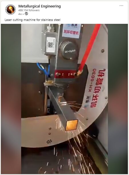
2. Stainless Steel Gets a Haircut
We can’t always articulate why a video is so engaging to watch. This laser-cutting video by Metallurgical Engineering is immensely satisfying. Cozy up with a bag of popcorn and watch the sparks fly!
3. Human Passenger Rocket Flights Are Ongoing
Pluto Aerospace has completed its second successful flight with paid passengers on its Dash prototype, a low-cost hypersonic testbed. Turn on Elton John’s Rocket Man and be inspired to join in the fun.
4. Where High Temp Insulation and Mona Lisa Kiss
Chiz Bros is donating a beautiful piece of art called Bessemer Reflections: Steel in Your Face. That image fittingly reminds us that metal work is both science and craft.
5. Heat Treatment Gets a Taste of Dijon
Dijon, France that is. Our European representative, Hamilton Pearman, recently attended the A3TS Annual Conferenceand Heat Treatments and Surface Engineering Show! A shout out to all of our materials science and thermal processing buffs who also attended!
6. The Summer Camp You Always Wanted
Did you know that Forging Industry Educational and Research Foundation puts on a Forge the Future Summer Camp? You know how we at Heat Treat Today love our Heat Treat Kids, and now we can’t wait to send them off to get their little toes wet in heat treatment.
7. Don’t Slip Past This Leak Detection Resource
From history, to big picture, and practical tips, this Heat TreatRadio has everything you need to stay well-informed.
8. The Furnace is Always On At Heat TreatToday
You might think that furnaces and fire would cause enough sweat for our team. But no. They chase it… and win!
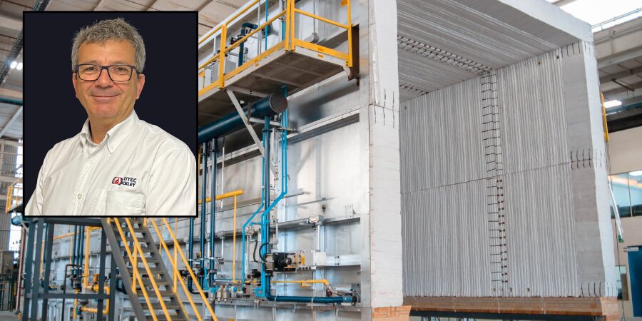
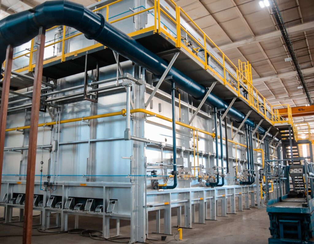
A heat treater in the U.S. Midwest anticipates greater heat treat abilities of ingots with a new gas-fired car bottom furnace. The furnace will be capable of handling both steel and aluminum ingots, with loads up to 150,000lb per cycle.
NUTEC Bickley designed the furnace to operate across a wide temperature range. The high levels of temperature uniformity to be delivered by the combustion system mean that this furnace will be qualified to undertake AMS2750 compliant surveys.
Arturo Arechavaleta, NUTEC Bickley’s vice president of Metal Furnaces, said: “Our customer for this important project has been serving the industry with a dedicated heat treat facility for many decades, and is a widely recognized and trusted name in steel and aluminum circles.”
The working dimensions of the furnace are 12ft w. by 35ft l. by 14ft 6in h. Normal operational temperatures range between 300°F (150°C) and 1650°F (900°C), with a maximum of 2000°F (1095°C). With burners firing above and below the load, there are 11 automatic control zones (five top, six bottom). The optimum approach to heat treat these heavy loads is pulse firing with variable excess air.
The furnace uses high-velocity nozzle-mix burners in a staggered configuration to fire above and below the load, maximizing heat transfer and providing optimum temperature uniformity. One of the IMPS® (Integrated Multizone Pulsing System) modes is Excess Air Firing. Among other things, it allows control over very low temperature while high turbulence is maintained to achieve temperature distribution.
In the Ratio Firing mode, the air and gas valves pulse in a synchronized pattern, from low to high fire in stoichiometric ratio, to ensure optimal fuel efficiency. This is made possible by using the kinetic energy generated by the flame speed and the rapid transition from low to high fire which increases entrainment and turbulence, thus promoting a better temperature distribution without the need for a high level of excess air.
Press release is available in its original form here.
A new reheating walking hearth furnace has been commissioned for Wieland Rolled Products North America. The new furnace has a processing capacity of up to 110 metric tons per hour and will support Wieland’s expansion plans in the production of high-grade copper products.
Greg Keown President Wieland Rolling & Recycling Source: Tenova
Wieland Rolled Products North America was delivered the furnace by Tenova, which is integrated with a selective catalytic reduction (SCR) deNOx emissions control system. The equipment will enable Wieland to expand the production of high-grade copper products, essential for several key industrial sectors. This installation is a key element of Wieland’s broader investment to upgrade and expand its East Alton, Illinois facility.
“We are pleased to continue our collaboration with Tenova as we enter the next phases of this expansion project. Their technology and project management expertise are expected to support our production goals and sustainability efforts,” said Greg Keown, president of Wieland Rolling & Recycling.
Francesco Memoli remarked, “This project is particularly meaningful for us because it integrates advanced combustion and fume treatment technologies to meet both performance and environmental targets. It’s a clear example of how we tailor heat treatment solutions to the unique requirements of non-ferrous production.”
Francesco Memoli President & CEO Tenova Inc. Source: Tenova
The furnace, engineered by Tenova Italimpianti, has a processing capacity of up to 110 metric tons per hour. Powered by a natural gas combustion system, it features Tenova’s proprietary TR Flat Flame Roof burners equipped with integrated recuperators and post-combustors. The configuration ensures a substantial 90% reduction in NOx emissions. This technology has already delivered positive environmental performance in both reheating and heat treatment applications.
Wieland’s expansion project includes a new hot rolling mill designed to increase production capacity for copper and copper alloy components used in electric vehicles (EVs), EV charging networks, and renewable energy systems.
Press release is available in its original form here.
This list of cybersecurity acronyms was compiled by the late Joe Coleman, former cybersecurity officer at Bluestreak Consulting™. Joe wrote a regular column called the Cybersecurity Desk in Heat Treat Today’sprint publication.
“Even if a heat treater is not a DoD contractor or in the DoD supply chain, NIST 800-171 is a great “best practice” standard for any organization to improve overall cybersecurity health. This will help in obtaining future orders because customers will know critical data is secure.” – Joe Coleman
CLICK BELOW TO VIEW OR DOWNLOAD THE CYBERSECURITY ACRONYMS LIST
CLICK TO VIEW OR DOWNLOAD THE CYBERSECURITY ACRONYMS LIST
About The Author
Joe Coleman
Joe Coleman was the cybersecurity officer at Bluestreak Compliance, which is a division of Bluestreak | Bright AM™. Joe worked for over 35 years in diverse manufacturing and engineering positions. His background included extensive training in cybersecurity, a career as a machinist, machining manager, and an early additive manufacturing (AM) pioneer. Joe presented at the Furnaces North America (FNA 2024) convention on DFARS, NIST 800-171, and CMMC 2.0.
In this Technical Tuesday installment featuring Combustion Corner by Jim Roberts, president of U.S. Ignition, readers are enlightened about how upcoming policies might impact their burner systems, fuel mixtures, and equipment. Could certain policies impact technical requirements of heat treating? Find out more below.
This informative piece was first released inHeat Treat Today’sJuly 2025 Super Brands print edition.
A furnace guy goes into a bar and says, “This looks like a fast crowd… and all the players nod in agreement.”
Where are we? It’s the future! And in heat treating and combustion circles, the changes that will occur in the next several years will be very impactful to our industry. We’ve all heard these things, and we have some of the very best experts in the world working for us in this industry to make sure that we continue to grow and to be a leader in the legislation and rules that could cripple the wonderful world of heat treating and metals.
We are lucky to have industry associates at the Metal Treating Institute (MTI)who understand the impact of some of these new regulations. In this year’s Air & Atmosphere issue of Heat Treat Today magazine, Michael Mouilleseaux (Erie Steel LTD) provided updates on the proposed decarbonization initiatives. I have seen presentations by Michael and his committee composed of Heather Falcone (Cook Induction Heating Company) and Ben Gasbarre (Gasbarre Thermal Processing Systems). This is critical knowledge for us all, and we should be staying as vigilant and supportive as we can. Michael’s interview is a must-read in that February issue – if you missed it, go back and read it. Please.
And then you say, “What’s this got to do with combustion equipment and the stuff that this Roberts guy is normally talking about?”
Well, not only does the decarbonization mandate mean the possibility of costs through government burdens and penalties, but the equipment and process change requirements are going to be staggering if we don’t prepare.
As long as I’m in a name-dropping mood, I’m going to mention Brian Kelly of Honeywell. Brian is a degreed aerospace engineer, and yet he decided to come play in the mud with us furnace guys for a career. Brian has several detailed presentations online about some of the prime initiatives for all the combustion equipment companies — hydrogen Combustion. Yep, the “H” word. The holy grail of zero pollution. One of those presentations includes fascinating detailed data on hydrogen and other emission initiatives, given by Brian Kelly and Todd Ellerton on YouTube regarding future combustion technology requirements.
“So, what does the “three times faster” thing mean, Jim?”
Well, all major combustion equipment companies, like Honeywell, understand that hydrogen requires three times the amount of fuel to generate the same amount of available heat as natural gas. Hydrogen also burns with seven to eight times the “flame speed” of natural gas. It burns, on average, about 400 degrees hotter (F) than natural gas. And so, from an engineering standpoint, there are a fantastic number of variations that must be considered as we look forward, especially when addressing CO₂ and other emissions. Add propane, butane, methane, producer gas, landfill gas, and anything else that is presently being utilized in the heat treat circles, and that provides a lot of possible variations!
Now, it needs to be said that a good many burners can burn hydrogen already. The anticipation of this level of scientific and ecological requirements was seen a long time ago. Conversely, many cannot. Brian Kelly explains that 17% of the present pre-mix/blended fuel systems cannot utilize this fuel. It also bears mentioning that there are three different grades of hydrogen production levels.
So, let’s start doing the math on how many iterations it will take. But here is the biggest tidbit of hydrogen science in the combustion world – hydrogen is the smallest molecule and the lightest in a molecular sense. Helium is smaller and lighter, for fact-checker purposes, but we aren’t trying to burn helium, are we? So, as we blend hydrogen with our other fuels (i.e., the most practical way to maintain some of the infrastructure and equipment), we need to have our combination equipment suppliers test and verify that which exists will work.
Obviously, if it takes three times the fuel volume, existing gas delivery lines will be an issue. At the molecular level, smaller and lighter means that many existing seals, connections, and control valves may no longer be gas-tight and may leak. That’s not good! If the flame speed of these fuels is five to eight times that of existing fuels, temperature profiles within the process will need to be reviewed and re-calibrated. And if it burns 400 to 500 degrees hotter, certainly that will require a review of the former materials of construction.
So, how does this tie into the original theme of “The future is coming fast?” Well, we have just touched briefly on one possible fuel transition that is on the horizon. Carbon points/credits are already being taxed in Europe. We can bet that these global decarbonization efforts will be moving ahead. We will need a review so that a “head in the sand” mentality does not catch any of us in the thermal processing community flatfooted and ill-prepared.
It’s easy to think that it won’t affect you. When I mentioned “three times as fast,” of course, I was alluding to the fuel references, and the best way to be prepared for the future is to see it coming. Be alert and stay current, and we will adapt as an industry, as we have so many times before. Until next time …
About The Author:
Jim Roberts President US Ignition
Jim Roberts president at US Ignition, began his 45-year career in the burner and heat recovery industry focused on heat treating specifically in 1979. He worked for and helped start up WB Combustion in Hales Corners, Wisconsin. In 1985 he joined Eclipse Engineering in Rockford, IL, specializing in heat treating-related combustion equipment/burners. Inducted into the American Gas Association’s Hall of Flame for service in training gas company field managers, Jim is a former president of MTI and has contributed to countless seminars on fuel reduction and combustion-related practices.
For more information: Contact Jim Roberts at jim@usignition.com.
A prominent aerospace company known for producing advanced, high-precision components for the global aviation and aerospace engine industry has been shipped a vacuum carburizing furnace. Headquartered in North America, the company’s aerospace division has been a trusted resource for the aeroengine sector for decades.
Vacuum carburizing furnace for aerospace Source: Solar Manufacturing
To support the development of a specialized carburizing process, Solar Manufacturing partnered closely with the R&D team at its sister company, Solar Atmospheres, a heat treating affiliate. Collaborative testing was conducted at Solar Atmospheres’ Technology Center in Souderton, Pennsylvania, where engineers from both organizations worked together to fine-tune the process to meet the specific metallurgical specifications.
“This collaboration was invaluable in achieving the desired metallurgical results,” said Rick Jones, regional sales manager at Solar Manufacturing.
The delivered system features a graphite-insulated hot zone measuring 48” wide × 48” high × 60” deep, capable of reaching temperatures up to 2400°F (1370°C). The furnace can accommodate workloads up to 5,000 pounds and includes an internal gas cooling system that provides rapid 2-bar nitrogen quenching.
Press release is available in its original form here.
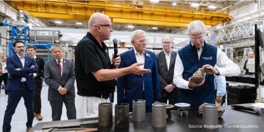
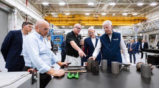
Bluewater Thermal Solutions showcased its contributions to innovation in the energy and industrial sectors, including Ultra-Fast Boriding at Argonne National Laboratory. U.S. Department of Energy’s Secretary, Chris Wright, engaged in a dialogue there on the future of transportation, manufacturing, and critical materials research.
Craig Zimmerman, Director-Technical at Bluewater, joined fellow leaders from national labs and industry at Argonne’s Materials Engineering Research Facility (MERF). Bluewater highlighted its collaborations with Argonne National Laboratory’s pioneering work in Ultra-Fast Boriding surface hardening technologies for down-hole oil production operations, which play a vital role in supporting domestic energy production.
“We’re deeply committed to advancing U.S. manufacturing through technical innovation,” said Zimmerman. “Participating in this event alongside Secretary Wright and our colleagues at Argonne highlights the successful development and transfer of new technology from Argonne to Bluewater Thermal Solutions.”
U.S. DOE Secretary surveys components at Argonne National Laboratory. Source: Bluewater Thermal Solutions
Argonne’s mission is to accelerate innovation from discovery to deployment, strengthen domestic supply chains for critical materials, and make the movement of people and goods more efficient and sustainable. Bluewater’s contributions help scale thermal technologies that bolster reliability.
Press release is available in its original form here.
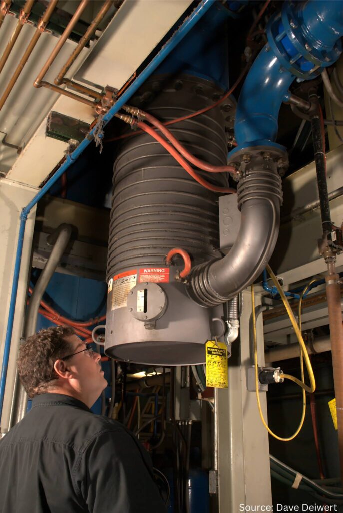
Helium leak detection is critical to ensure system integrity, product quality, and operational efficiency in vacuum processing. With 36 years of hands-on experience, Dave Deiwert of Tracer Gas Technologies joins host Doug Glenn on the most recent episode of Heat Treat Radioto share a wealth of knowledge on the evolution of leak detection technology, practical maintenance, and best practices for leak testing.
Listeners will gain practical insights into the best leak detection practices and how to troubleshoot challenges.
Below, you can watch the video, listen to the podcast by clicking on the audio play button, or read an edited transcript.
The following transcript has been edited for your reading enjoyment.
Introduction
Doug Glenn: Helium leak detection has come a long way, but not everyone has a brand new piece of equipment. So let’s talk about some of the shortcomings of older equipment and some of the improvements that you’re seeing.
Dave Deiwert: When I started in 1989, leak detectors pretty much had what were called oil diffusion pumps as the high vacuum pump. That’s the pump that creates the vacuum for the analyzer cell or mass spectrometer so they can separate helium from other gases. These diffusion leak detectors did not like to be shut down improperly or have power outages quite frequently.
You would hear stories of somebody that turned the power off of a leak detector without a proper shutdown or a power outage, and that could cause an oily mess from the diffusion pump, and maybe even crack the oil. So, you would end up having quite a maintenance event required on the leak detector before you could use it again.
In fact, these kinds of problems happened so frequently that in my young sales days when turbopump leak detectors first were introduced, as I would go in to show it to a potential client, one of the first questions was, “What happens if you have a power outage?”
I would have a little fun with that.
I’d say, “Well, let’s find out.” And I would pull the plug out of the wall, and they would say, “Oh, you can do that?” And of course you could. A turbo pump would just coast down towards a stop. Then we turn the power back on, and it’s back up.
Part of what compounded this problem with the diffusion pump is that it works by heating oil to jet mist oil vapor that goes to the top, and it’s condensed and directed back down. When power is lost, whether you turn the power off with an improper shutdown or a power outage, that pump is still hot for quite a while. It’s still trying to pump, and the backing pump, whether it’s a diffusion pump or a turbopump, is typically a rotary vane pump. With a power outage or power stop, those pumps will come to a stop very quickly. But those diffusion pumps and turbo pumps are not designed to exhaust atmosphere, so the backing pump or rotary pump comes to a stop pretty quickly, and now you have atmosphere potential on the exhaust of the diffusion pump.
The turbopump survives that much more nicely than a diffusion pump does. So the first major upgrade in the technology across the board with all the manufacturers was moving away from diffusion pumps to turbo pumps. If you buy a new leak detector from the ‘90s to today, it will very likely have a turbo pump no matter whom you buy it from and even if you buy a used one.
Size and Portability of Leak Detectors (00:06:09)
Doug Glenn: How large were these original pieces of equipment? Did you have to wheel them around?
Dave Deiwert: The very first ones I worked with predominantly would be the size of a washer/dryer. They would typically have casters on so you can roll them around.
They took up more space and certainly took up a lot more energy. You could sometimes find what they would call portable leak detectors, but they would still have diffusion pumps in them, and they’d have less features because of how small they were versus the console leak detectors.
Doug Glenn: So now nowadays they use helium leak detectors.
Dave Deiwert: Most everybody’s gotten away from console leak detectors. You can find a couple companies that have a fairly large rolls-on-caster leak detector that still has turbo pumps, and higher performing backing/ruffing pumps. But the majority of leak detectors you’re going to find are more portable and smaller in size.
Doug Glenn: Are they close in size to a briefcase?
Dave Deiwert: They average 12 to 18 inches wide by 10 to 12 inches deep and 12 to 14 inches tall, approximately. So, much smaller than a washer/dryer.
Quite frequently, these leak detectors may be sold with a cart so that you don’t have to carry them from point A to point B. It can be a little laborious to still carry them. They weigh 40 lbs or more. So quite often, the first accessory purchased with the leak detector is a cart to roll it around.
Doug Glenn: So it’s a heavy piece of carry-on luggage essentially.
Dave Deiwert: Absolutely.
Maintenance: Old vs. New Leak Detectors (00:06:37)
Evaluating a vacuum furnace for leaks
Doug Glenn: How would you compare the maintenance of those older units, assuming that you don’t lose power, versus maintenance of the newer units.
Dave Deiwert: A stereotypical experience from my field service days would be if you’re running a diffusion pump leak detector in a production environment, using it every day, then most likely you’re going to do what I call an overhaul of the leak detector. During this overhaul, you’re going to change your oils, change the filaments in the mass spectrometer, put on new valve seats, and clean the manifold.
Not everybody will do this. There are those that might go a year or two, especially if the leak detector is purely for troubleshooting, like if you have only a few furnaces. The leak detector may sit against the wall, and then you go get out to leak test a furnace. They may well get a couple of years of use out of a leak detector before needing to do any preventative maintenance or even a major overhaul.
With the new turbopump leak detectors, I think all the manufacturers now have models that most likely you’ll go multiple years without really doing anything other than changing oil in the backing pump, which you might do a couple times a year or so, keep an eye on the oil level, much more maintenance friendly and easier to do the troubleshooting and the service to it.
Filament Technology Improvements (00:08:10)
Dave Deiwert: The next major upgrade in the leak detectors across the industry was the filament design.
The old diffusion pump leak detectors predominantly had tungsten filaments, which, if you’ve ever cracked or seen a cracked light bulb that had a tungsten element in it, you know that immediately you lose the function of the light bulb. And the same thing with the filaments that are tungsten in a mass spectrometer. If it gets a pressure burst, which is what I call the event when somebody disconnects the test port from the vacuum furnace while the leak detector is still in test, that allows a pressure burst into the leak detector and tungsten filament, and most likely you will burn out the filament. As a result, you will have a maintenance event for that.
As a rule of thumb, you will get 1,000 to 2,000 hours out of an old leak detector with tungsten filaments, but you’re going to get many thousands of hours out of a Yttria coated-iridium, which I think is used across the board in the industry today. In the case of
several years even, it greatly reduces your cost of ownership with the newer leak detectors.
Performance and Cost Comparison (00:09:12)
Doug Glenn: Are there any other major differences between the old units and the new units?
Dave Deiwert: There are some extra benefits from the upgrades that we’ve talked about. The turbopumps will allow, at least modern leak detectors, us to test at a higher pressure (or less vacuum). You press “Start Leak Detector.” The test port pressure pumps down to some vacuum level. For diffusion pump leak detectors, they had to get down to typically less than 50 mTorr. Depending on the model, definitely significantly lower vacuum than the turbopump leak detectors. So, the turbopump ones with the gross leak testing capabilities, you’re probably looking at 18 to 20 torr. I think a couple of manufacturers claim they can get in the test pretty much right below atmosphere and start looking for very massive leaks.
The capabilities going to turbopump and Yttria-coated filaments has allowed manufacturers to greatly improve the performance and the robustness and reliability of the leak detectors.
Doug Glenn: In terms of cost comparison, are newer units more or less expensive than older units?
Weighing the costs and comparisons of different units
Dave Deiwert: When buying a leak detector in 1889 to early ‘90s, you’re probably looking at the low to mid-20s in price. You’re going to find they are a little higher than that now. With the market and inflation, you’re probably looking at upper 20s to low 30s for the most typical leak detectors that are purchased for the vacuum furnace industry. You can find some that are maybe two or three times that amount, but those are not needed for the industries that we’re talking about today.
Troubleshooting and Service Efficiency (00:11:00)
Dave Deiwert: If the client, their suppliers, or people who work on the leak detectors from time to time service a diffusion pump leak detector, they may want to explore an idea to troubleshoot a problem. They may not be sure what the problem is yet.
First, you’re going to do a proper shutdown of the diffusion pump leak detector to protect the oil in the diffusion pump and the cleanliness of the leak detector. You may wait a good part of an hour for that diffusion pump to cool off before you can try the troubleshooting solution you’re going to investigate. Then you’re going to wait for another good hour for it to heat back up and be ready to confirm if what you have tried to do was successful.
With a turbopump leak detector, you turn a switch off to turn the power off, and within minutes you can test out the solution on the leak detector. So you greatly expedite your troubleshooting time.
What might have been almost always a full day event of troubleshooting and servicing a diffusion leak detector turns into less than a half day, possibly even an hour or two.
In every category, the newer leak detectors are very attractive. If clients or our viewers reach out to their suppliers or potential suppliers, there will most likely be some trade-in value for your old leak detector, which will also help offset the pain and suffering of spending money on a new leak detector.
Doug Glenn: Hopefully they’ll come pick it up, too.
Where to Connect Leak Detectors on Furnaces (00:14:11)
Doug Glenn: In your column, you talk about how there’s some debate amongst users on where to hook up the leak detector on the furnace. Can you walk us through that a bit?
Dave Deiwert: I run into people who are very adamant that you hook up the leak detector in one of three places. And I’ve told salespeople that while we have our preferred location of where to hook to the leak detector, we should never visit a client and tell them they are doing it all wrong. As a field service engineer, I’ve confirmed that you can connect the leak detector at three most prominent locations, but the question is where is the most optimum place to connect it?
Leak testing a vacuum furnace
The first place is hooking the leak detector directly up to the furnace chamber, because that’s where they imagine the leaks might be. The next two locations might look like close cousins because they’re both in the series flow away from the chamber, through the pumps and out to the exhaust.
My preferred location is to connect it between the blower and the chamber. Or, if there’s
a diffusion pump, I would connect it between the blower and the diffusion pump.
The last place that you might see somebody connect it is between the blower and the backing pump or a roughing pump. They might do this to use the blower almost like a turbocharger to improve the signal to the leak detector. The disadvantage of doing that is most likely these vacuum pumps are very dirty single-stage roughing pumps. There are two concerns I have with this. One is the back stream of oil or hydrocarbons from that pump to the leak detector. And the second is the potential for back streaming, even of helium from the ballast port of the pump or the exhaust, depending on where the exhaust is terminated. If somebody exhausts the pump directly out of the building, then that’s not so much a concern. But if you connect it between the blower and the diffusion pump or the blower and the chamber, then you’re allowing the roots blower to be like an optically dense filter between the leak detector and that backing pump.
And for the two concerns that I mentioned earlier about either back streaming of helium from the leak testing or back streaming hydrocarbons from the vacuum/roughing pump, the optimal location would be to hook it up between the blower and the chamber, or if it’s a diffusion pump, between the blower and the diffusion pump. If you’re hooking it up between the diffusion pump and the roughing pump, you need to make sure that you pump down to your base pressure before you open up the valve from the leak detector to that point. You don’t want to potentially suck any diffusion pump oil into the into the leak detector.
Furnace Connection Points and Hardware (00:15:50)
Doug Glenn: Is there a feed through meant for leak detection built into the furnace, between the blower and the diffusion pump or roughing pump or on the chamber?
Dave Deiwert: There is almost always a connection point where I describe my preferred location, especially with furnaces manufactured in the last twenty years. On new furnaces sold today, it’ll be an NW25 flange, which will match up directly to the leak detector.
With the leak detectors in this industry, we’ll have an NW25 flange, which is a standard vacuum connection. You run a bellows hose from that leak detector to that point on the furnace.
I like to see a manual ball valve that’s always on the furnace at that point. You can put a blank cap on the exposed port on that valve, which can act like a dust cap. It’s always there. This facilitates doing a PM leak check, which we might talk a little bit more about later.
Now, sometimes you may go to hook it up between the blower and the furnace or the blower and the diffusion pump and there’s no connection there.
I’ve seen that, so you have to work with what you’re given. You might well see there’s a port between the blower and the backing roughing pump,
and you can use that. It’s just not the optimal place to put it.
If you put the leak detector directly on the chamber, typically there’s a small port that you can hook up to, now you’re going to be competing in what we call molecular flow with a much larger opening going to the blower. The lion’s share of helium is going to go out that large target to the blower, and you’re not going to get as much helium signal to the leak detector. So, putting the leak detector port basically right into the end of the flow, going to the blower lets you sample the flow going in that direction.
Doug Glenn: Right, which is going to be the bulk of it.
Dave Deiwert: Yes, and you’ll find a faster response time and faster cleanup and recovery of the leak rate signal when you stop spraying the helium by putting it in that location.
PM Leak Checks During Furnace Operation (00:18:05)
Doug Glenn: You briefly discussed conducting PM in the column. Can you walk us through conducting a PM leak check during a live operation of the furnace.
Dave Deiwert: First off, when you’re going to do a preventative maintenance (PM) leak check on the furnace, there are two scenarios. In the first scenario, you’re not running the furnace today. So, you roll the leak detector up and you look for leaks that you may not know are there when they’re smaller and less noticeable, so you can either mark them or repair them at your convenience before they get to be larger and more noticeable, maybe affecting quality of your process.
The second scenario is that you have a very long process. You might have enough time to do a leak check while the furnace is in process. Helium is an inert gas. If you pull a vacuum on your furnace to do some heat treating, and it’s going to be in that vacuum level for an hour or more, this may be plenty of time to do some leak testing. We definitely don’t want to compromise quality. But again, helium is an inert gas, and if you have an experienced person doing this PM leak check in an orderly fashion, it can be done safely.
Basically, you roll the leak detector up to that closed ball valve, and you would have to have the ball valve in place there if you’re doing this during a live process. So you connect the hose from the test part to this closed ball valve. You start the leak detector and put it in test. I suggest that after you put it in test, you ensure you have a good vacuum test level vacuum from the leak detector to the closed valve.
Because we don’t know initially if the vacuum level is different on the other side of the valve,
Heat Treat Radio #123 Host Doug Glenn and Dave Deiwert
I recommend momentarily stopping the test of the leak detector. I think all modern leak detectors have a standby mode so you’re not venting the test for a leak detector. You put it in standby, then you open the ball valve, and the leak detector computer can now see if the vacuum level changed to maybe potentially a level a little higher than what it wants to be at. That allows it to tell itself to pull some more vacuum along with the furnace before we actually open the test valve to the analyzer cell or the mass spectrometer.
If you’re in test, you open the ball valve, and somebody forgets that step, there can be a little vacuum differential and you may shock the leak detector and throw it out of test. This doesn’t hurt the leak detector. You just have to go and press test again. But by putting it into standby and then opening the ball valve, then putting it back into test, this saves you a step.
Once you put it into test, the next thing you’re going to make a note of is the background level of helium before you start spraying helium. I’m a big fan of people who leak test their furnace, or really anything no matter what market is, and take care of their furnaces purposefully.
If you don’t suspect any leaks or it’s a brand new furnace, you can hook your leak detector up and you put it in test, and before you spray any helium, make note of what I call the background helium signal. This is a result of any natural helium that’s in the furnace. There is five parts per million helium in the air we breathe. There’s going to be helium in the furnace, and take note of what that is.
Let’s say you notice you have two times ten minus nine background of helium on the display of the leak detector, and you haven’t sprayed any helium, you can make note of that.
So now you know you’re going to be looking for leaks for some delta change increase of that value. From there, it’s playing the hot and cold game as you pinpoint where the leak isas you spray helium.
You can do this potentially while a furnace is in process. You certainly want everybody to know what you’re doing and have an opportunity to discuss this because it could make people nervous, especially the quality manager or even the production manager. It’s something that should be talked about with the whole team to ensure everybody sees the value in it.
So we spray helium and make a note of anything we see. Next time we have an opportunity, when no production is going on, we can fix that leak at our convenience rather than wait until it might get worse.
Doug Glenn: Certainly we would want to consider whether that should be done with high-value items in the furnace.
Dave Deiwert: Yes, unless everybody is on board and understands, and you’re doing things purposely.
If you are doing a PM leak check on a sensitive process and quality of a product and you’re done testing, that manual ball valve needs to be closed before you do anything else to the leak detector. If you forget, and you press vent on the leak detector, it’s going to try to vent that whole furnace through the little vent valve of the leak detector, and that’s not going to be good.
This whole discussion point is that everybody on the team would need to buy into this idea and be very clear about what we’re going to do, how we’re going to do it.
I’m just suggesting it’s something that can be done, and if you confirm it works for you, it has value. It’s just another option for somebody to optimize the way they take care of their furnace.
Confirming Leak Location Before Repair (00:23:38)
Doug Glenn: When you’re isolating a leak, how important is it to assume or not assume that you found the leak once you get a reading on the on the meter?
Dave Deiwert: I spend a lot of time on this topic in every class that I teach because nothing is more frustrating than thinking you have found the leak when you haven’t.
Let’s say you think have found the leak on some big 10-inch gate valve. Maybe it’s too heavy for one person you have to have someone to help you take this gate valve off the system. Once you take the gate valve off the system, you put a repair kit in there, clean everything, you put it back on the furnace, and everything’s assembled. You start to furnace back up and you do a leak check and realize you still have the same leak you thought you fixed. There may be other flanges you need to check, which might require more help.
You absolutely, beyond the shadow of doubt, can know that you have found the leak because every time helium is sprayed at that place where you think the leak is, you should get the same response, same response time, same peak leak rate.
If I spray the helium at point A, where I think the leak is at, and I stop spraying, I wait for the leak rate to go back to baseline, then I go back to spray it again. The more work that is involved, the more I’m going to want to duplicate that response and make sure that is where the leak is at.
Last thing you can do, just to be sure, is what I call the “x, y, z axis.” Try to spray helium left, right, up, down, back and forth, just to make sure you’re not getting a better response to something else nearby.
Doug Glenn: By better response, do you mean a higher measurement of helium that comes through or comes through more quickly?
Dave Deiwert: That’s correct. Now, you might have the problem where there are 2, 3, or 4 connections right in the same general area, and it’s difficult to pinpoint where I’m getting I think the same response, no matter where I’m spraying the helium. To remedy this, you can put a barrier between two fittings. This barrier could be plastic, tape, putty, your hand. Try to put some barrier between the two connections so when you spray on one side now, you’re not really getting the same response you were before and can pinpoint the location of the leak more accurately.
This is an important step before you repair or remove something. If you remove a NW25 flange and you’re wrong, there’s not a lot of pain and suffering. But I guarantee you 100%, you can prove to yourself with some patience and some diligence where the leak is before you do the work of disassembly and service.
Doug Glenn: It is better to invest a little time in detection than to repair something that doesn’t need to be repaired or find out later that you fixed the wrong piece.
Dave Deiwert: Absolutely.
Repair vs. Replace: Leak Source Components (00:26:44)
Doug Glenn: Once you do find the leak and it’s through some sort of a device, whether it’s a feed through or a control or a valve, how do you decide whether to repair that item or replace it?
Discerning when to repair or replace
Dave Deiwert: If the device is something that you can disassemble, and if the manufacturer has a repair kit (a valve is a good example of that), I would recommend that you go ahead with a repair. You have already taken it apart, I would put the part in a repair kit, if you have one, to try to lengthen the time between now and the next time you look at it.
If it’s a piece that has no repair kit, then obviously you will need to repair it or replace it, depending on your skill level and what it is you’re looking at.
If you’re looking at thermocouple and the feed screws on it are leaking, you may be a little limited in what your options are. Can you apply a vacuum-friendly sealant to brush around the feed throughs to see if that would solve the problem? That may be an option. What is the cost of that thermocouple? If it’s a $20 item, I’m probably going to put another thermocouple on there. If it’s a $1,000 item, I might try brushing some vacuum-friendly sealant on and see if that takes care of the problem.
One time, I found a leaking rotary vane pump, back in my field service days.
These all have repair kits where you can replace all the gaskets, the vanes, everything. But I didn’t have one. This was early in my young career. I talked to the factory about getting one and they were going to send one. But I told the client that we had nothing to lose. Let’s open it up, see what we can find. So, we open that pump up, and it looked pretty bad inside, but we cleaned everything up, even the gaskets, put a little vacuum sealant on, and put it all back together. We made it leak tight, and we got it running again. If I had a repair kit, I’m already there, then let’s go ahead and put the repair kit in. But if you don’t have one, there’s nothing wrong with taking it apart and seeing if cleaning and
reassembly gets it going for you.
Rotary Vane Pump Field Advice (00:30:30)
Dave Deiwert: I’m going to give a little free advice, no extra charge, to people talking about rotary vane pumps. In my career, I’ve come across quite a number of rotary pumps that were having an issue. I can count on one hand, however, how many times I wasn’t able to just clean it, put it back together, and get it going again with fresh oil. And both those times involved a shaft seal leak. So, if you don’t have a shaft seal leak, in my mind, you’ve got nothing to lose by taking a rotary vane pump apart, cleaning it, and putting some fresh oil back in it.
If you’re using solvents, when you take it apart, make sure those are solvents cleared back out of there
because solvents and oil don’t play very nice. You want to make sure that solvents have been removed and degassed from your pump. This may require that you put oil in it, run it for a little while, then flush it, and put some oil in to make sure you don’t have anything remaining behind.
A little willingness to get your hands dirty, open up the rotary vane pump, and a very good chance that you can get it going by just doing that.
Doug Glenn:All right, Dave. Appreciate the good advice and your expertise.
About the Guest
Dave Deiwert
Dave Deiwert has over 35 years of technical experience in industrial leak detection gained from his time at Vacuum Instruments Corp., Agilent Vacuum Technologies (Varian Vacuum), Edwards Vacuum, and Pfeiffer Vacuum. He leverages this experience by providing leak detection and vacuum technology training and consulting services as the owner and president of Tracer Gas Technologies.
Learn more about Dave from Heat Treat Today’s July Digital Edition’s Meet the Consultant page.
A manufacturer of heavy duty gas turbines has ordered a vacuum furnace with screen insulation and molybdenum heating elements. Siemens Energy Global will be provided the furnace by a company with U.S. locations and it will be used mainly for brazing gas turbine hot path parts like blades & vanes.
Maciej Korecki Vice President of the Vacuum Segment SECO/WARWICK
Siemens Energy Global has chosen SECO/WARWICK to provide the vacuum furnace. The device on order includes a mechanical pump, an efficient Roots pump, and a diffusion pump. The molybdenum heating chamber ensures a required temperature distribution and provides process cleanliness.
“The Vector vacuum furnace solves the partner’s problem of heat treating an increased number of large blades & vanes requiring a high degree of cleanliness in both the brazing and annealing processes. The Vector will relieve the production burden on the current equipment in operation in the client’s manufacturing & repair facility in Berlin.” said Maciej Korecki, vice president of the vacuum segment, SECO/WARWICK Group.
Grzegorz Głuchowski Sales Manager SECO/WARWICK
“We used a molybdenum heating chamber, partial pressure system, dew point sensors, and a very efficient high vacuum system. An important aspect is also the fact that the furnace will be integrated with the client’s master system using the OPC Unified Architecture communication protocol. Thanks to this, we can connect with a wide range of machines and industrial devices,” commented Grzegorz Głuchowski, sales manager for SECO/WARWICK.
The heat treatment processes associated with this furnace are benefited by the ability to cool at 1.5 bar in argon.
Press release is available in its original form here.