Getting excited for the November print edition? In 2021, Heat Treat Today released the inaugural Vacuum Heat Treating print edition. This edition is set to release every November to help heat treaters better work their vacuum furnaces and vacuum heat treat processes.
This Technical Tuesday original content round-up shares the hottest vacuum heat treating articles from this past year as you bundle up for the cool weather this fall. Enjoy!
Graphite in Vacuum Furnace Fixturing
Let's talk about carbon/carbon composite --- C/C.
Why is the vacuum furnace industry excited about its use in graphite vacuum furnace fixtures, grids, and leveling components? Because it can be readily machined for special shapes and applications. The lighter-weight material is mostly composed of carbon fibers and a carbon matrix (or binder).
Contact us with your Reader Feedback!
As the authors of this article explain, "They are among the strongest and lightest high temperature engineered materials in the world compared to other materials such as basic graphite, ceramics, metal, or plastic. C/C composites are lightweight, strong, and can withstand temperatures of over 3632°F (2000°C) without any loss in performance." Intrigued, are you not?
Step-by-Step Guide To Choose Heat Treating Equipment (English / Español)
If it's time to choose an industrial furnace, let's break it down step by step:
Step One: Quote Request
Step Two: Supplier Selection
Step Three: Study and Evaluation of Offers
Step Four: The Price
Follow this guide and avoid saying things like "The substation and/or the cooling tower did not have the capacity"; "The equipment is not what we expected"; or “They never told us that the furnace needed gas in those capabilities." If there are steps you take when selecting an industrial furnace, let us know in a Reader Feedback note here.
Pressure vs. Velocity and the Size of Your Furnace
If you like the R&D world of heat treat, but also like to be grounded in practical heat treat solutions, this is the article for you. Read about what this commercial heat treat found out about how size relates to the pressure and velocity of vacuum furnace cooling rates. Here are the facts you will learn:
The greatest impact on the cooling performance in a vacuum furnace is to increase the___ ______ within ___ _____.
This is achieved by ______ __ ______ of the ______ ____.
Energy at Large: A Heat Treat Vacuum Furnace Case Study
If you like to read about how heat treaters can be game changers in multinational science projects, this is the article for you. A specially designed vacuum heat treat furnace was commissioned to heat treat critical components in a large energy generator. The heat treating of these components takes 5 weeks to complete; talk about a long, uniform heat treat period.
Read about the energy experiment, the heat treat furnace, and the heat treating process in this technical feature.
At Heat TreatToday, we want to make sure everyone in the North American heat treat industry is well informed so they can be happier and make better decisions. With that in mind, we have been growing our library of Spanish heat treating content.
Below, click the blue headings to learn from Víctor Zacarías about pyrometry standards in the aerospace and automotive industries, from Carlos Carrasco about selecting heat treating equipment, from Bill Munn about leadership and motivation, and from Erika Zarazúa about CQI-9's probe method A. If you'd like to view this content in English, click the America flag icon.
Víctor Zacarías General Director Global Thermal Solutions Mexico
"Las operaciones de tratamiento térmico son percibidas generalmente como cajas negras cuyos resultados son poco predecibles. Si bien, entendemos los mecanismos físicos involucrados para modificar las propiedades de un material, los hornos de tratamiento térmico son sistemas termodinámicamente imperfectos, y por ende los resultados finales en ocasiones también lo son."
Contact us with your Reader Feedback!
"Heat treatment operations are generally perceived as black boxes whose results are not very predictable. Although we understand the physical mechanisms involved in modifying the properties of a certain material, heat treatment furnaces are thermodynamically imperfect, and sometimes the final results are too."
This article first appeared Heat Treat Today's March 2022 Vacuum Furnace print edition.
Carlos Carrasco Founder Carrasco Hornos Industriales
"Este artículo ayuda a los ingenieros a comprar equipos de tratamiento térmico. Hay muchas razones para seleccionar cuidadosamente los hornos industriales. Uno, es el costo del horno en sí y otro, es que el producto que se está tratando térmicamente afectará los resultados de su empresa."
"There are many reasons to select industrial furnaces carefully. One is the cost of the furnace. Another is realizing heat treating will affect the product and the bottom line. There is more specialized engineering in heat treating equipment than is apparent from the outside."
This article first appeared in Heat Treat Today's November 2021 Vacuum Furnaceprint edition.
Bill Munn Leadership Coach Bill Munn Source: Bill Munn Coaching
Por definición, de aquí se desprende que no se desempeña solo; es más, está posicionado no solo para trabajar en conjunto con otros seres humanos sino también para liderarlos; si su potencial se ha de realizar, puede que ya haya entendido bien que en esas personas reposa la verdadera clave del éxito que a futuro pudiera conseguir ¿Cómo, pues, lograr su compromiso?
By definition, this means that you are not functioning alone. Moreover, you are positioned not only to work with fellow human beings, but to lead them. And if your potential is to be realized, you may already know well that those people are the true key to your future success. So how will you engage them?
This article first appeared in Heat Treat Today's September 2022print edition.
Erika Zarazúa Regional Purchasing Manager Global Thermal Solutions México Source: Global Thermal Solutions México
"Las pruebas SAT deben realizarse a todos los sistemas de control, monitoreo y registro de los equipos de procesamiento térmico. Esto no aplica para los sistemas de ‘alto-límite” cuya única función es la de proteger al horno de un sobre calentamiento."
"System Accuracy Tests (SATs) must be performed on all control, monitoring, and recording systems of thermal processing equipment. This does not apply to “high limit” systems, whose sole function is to protect the furnace from overheating."
This article first appeared in Heat Treat Today's August 2022 Automotive print edition.
Find heat treating products and services when you search on Heat Treat Buyers Guide.com
Imagine this: A huge lab facility nestled in the south of France . . . teams of scientists and technicians striving to bring carbon-free energy solutions to the world . . . “replicating the high-energy fusion reaction that powers the sun and stars.” To complete the project, what heat treat solution is needed? Read more in thisTechnical Tuesday to find out.
This article by Rafal Walczak,product manager at SECO/VACUUM, will be published in Heat Treat Today’s December 2022 Medical & Energy print edition.
Introduction
For this case study, we will discuss how SECO/VACUUM built a highly specialized custom heat treating furnace used in the construction of the central component of a large, multinational science experiment.
The Experiment
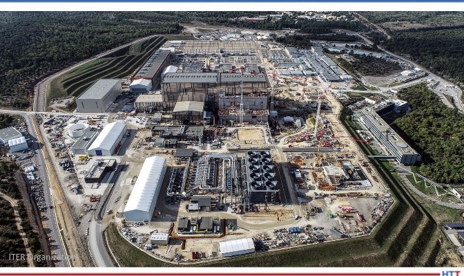
ITER (standing for International Thermonuclear Experimental Reactor and meaning “the way” in Latin) is the largest high-energy science experiment ever conducted. At a giant lab facility in southern France 35 countries, hundreds of vendors, and thousands of scientists and technicians are collaborating on a device to demonstrate the feasibility of clean, safe, carbon-free energy production by replicating the high-energy fusion reaction that powers the sun and stars.
Figure 1. ITER Laboratory at the Cadarache research center in southern France Source: ITER Organization
There are no solid materials that can touch, much less contain, such a high-energy reaction without immediately vaporizing. Instead, this super-hot cloud of plasma must be contained by a special configuration of magnets called a tokamak, which can trap charged particles in a toroidal or donut-shape cloud. This tokamak has 10 times more plasma containment volume than any other tokamak ever built.
The term “tokamak” comes to us from a Russian acronym that stands for “toroidal chamber with magnetic coils” (тороидальная камера с магнитными катушками).
The Magnet
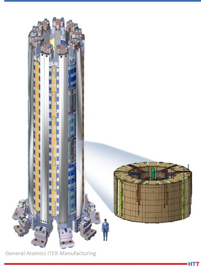
Figure 2. ITER central solenoid and one isolated solenoid module Source: General Atomics ITER Manufacturing
General Atomics’ Magnet Technologies Center near San Diego, CA was contracted to build the ITER tokamak’s large central magnet, the most powerful superconducting magnet ever built, strong enough to lift an aircraft carrier. Other magnets in the tokamak serve to contain the plasma. The central solenoid is an oscillating magnet responsible for inducing current in the plasma cloud similar to how an induction stove heats a pan, except it is heating the plasma to 15 times the temperature of the surface of the sun. Far too large to be constructed and transported in one piece, the 12-meter-tall, 4-meter-wide coil of wires must be built in six 2-meter-tall modules to be joined once they are all on site at the lab. A seventh module will be built as a spare.
Kenneth Khumthong, technical lead for final testing and fabrication certification for ITER Central Solenoid at GA, described the tests on each module of the magnet, saying, “We run a battery of tests on each and every module subjecting them to voltages as high as 30,000 volts and powering them with as much current as 40,000 amps. This is done to ensure that every module meets all of ITER’s specifications prior to shipping them out to France.”
Embrittlement vs. Field Strength Tradeoff
Other superconducting electromagnets in the ITER tokamak will be made using coils of relatively durable niobium-titanium alloy. Past experiments have demonstrated that magnetic fields greater than 12 Tesla disrupt the superconducting properties of Nb3Ti. The ITER central solenoid, however, must sustain magnetic field strengths above 13 Tesla. For this reason, the central solenoid coils must instead use niobium-tin as its superconducting wire, which more reliably maintains superconducting properties in such high magnetic fields but is also more brittle and too fragile to bend after reaction to Nb3Sn. In order to accommodate for the brittle wire, General Atomics had to first coil the wire and jacket into their final shape before heat treating the metals into their superconducting, albeit brittle, alloy Nb3Sn.
The Wire
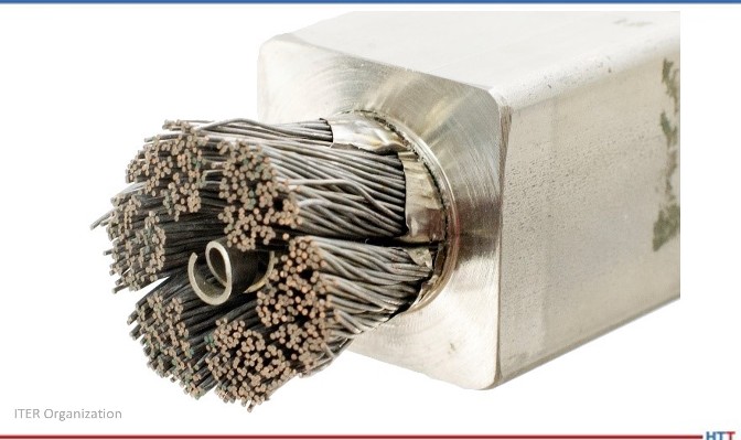
Figure 3. A dissection of the central solenoid conductor strands, central spiral, and structural jacket Source: ITER Organization
Niobium-tin wire strands react to become Nb3
Copper strands serve as traditional conductors to safely dissipate stored energy when the superconductivity experiences a disruption. The copper strands do not react with the niobium-tin.
A central spiral maintains a hollow channel to circulate liquid helium to chill the Nb3Sn wires to 4°K, below their superconducting temperature of 12°
Creating such strong magnetic fields inside a coil of wire will also tear apart the coil of wire itself if that wire is not supported inside a high strength jacket. The ITER central solenoid wire bundle is about 38.5 mm diameter, housed inside a 50 x 50 mm stainless steel jacket.
Total maximum current in the superconductor wire is 48,000 amps.
Worldwide niobium production increased six-fold for several years just to meet the niobium demands of the ITER project.
The Heat Treating Furnace
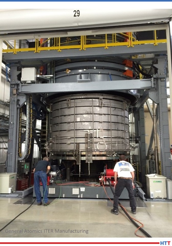
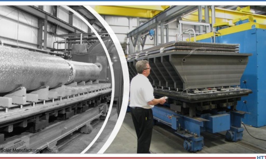
Figure 4. Technicians ensure proper placement before lowering heat treat furnace Source: General Atomics ITER Manufacturing
In order to convert the niobium-tin metal conductors into superconductors, each of these 4 meter by 2 meter 110 ton solenoid sections must be heat treated for five weeks, exceeding 1200°F (650°C) at its peak. The heat treatment serves to alloy the niobium and tin together into Nb3Sn, which becomes a superconductor when chilled with liquid helium to 4°Kelvin. No such heat treating furnaces existed, so General Atomics turned to SECO/VACUUM to build a custom heat treating furnace large enough to fit these solenoids and packed with all the technology needed to meet the strict quality control standards of this monumental experiment.
Five inch wide metal band heaters ring around the walls of the furnace with nearly 900kW of heating power. Covering 50% of the walls, they provide a very uniform heat. This is brought about by the following seven steps.
The Heat Treating Sequence
In addition to alloying the niobium-tin wires, the furnace also serves to remove the stresses in the stainless steel jacket housing the superconducting wire and to bake off any residual contaminants prior to reaching reaction temperature.
1. Complete a quality control test: Vacuum seal the untreated solenoid coil in the room temperature furnace and charge the inside of the conductor jacket with 30 bar high pressure helium to test for leaks after forming and welding.
Monitor furnace atmosphere with ultra-high sensitivity mass-spectrometer helium detectors.
2. Purge with argon gas while slowly ramping up heat.
This drives off hydrocarbons and oxygen before system reaches reaction temperatures.
Monitor furnace atmosphere with gas chromatograph to find impurities from residual oils and lubricants leftover from manufacturing process.
Monitor and control argon circulation and exchange with mass flow sensors and circulation blowers that penetrate the furnace lid with ferrofluidic feedthrough seals around the blower motor shafts.
3. Maintain at 1058°F (570°C) for about 10 days. Confirm stabilized temperature and pure atmosphere.
4. Proceed to 1202°F (650°C) for four days. This is the actual reaction phase that achieves the primary objective of converting the niobium-tin into the superconducting alloy Nb3
5. Very slowly and uniformly ramp back down to room temperature to avoid additional stresses in the coil.
6. Complete another quality control test: Evacuate the argon and once again vacuum seal the solenoid coil in the room temperature furnace and recharge with 30 bar high pressure helium to test for leaks after heat treating. Monitor atmosphere for the presence of helium, which would indicate a leak in the coil.
7. Only then is it ready for the post-heat treating stages of wrapping with insulation and encasing in epoxy resin for rigidity.
Options, Upgrades, Special Features
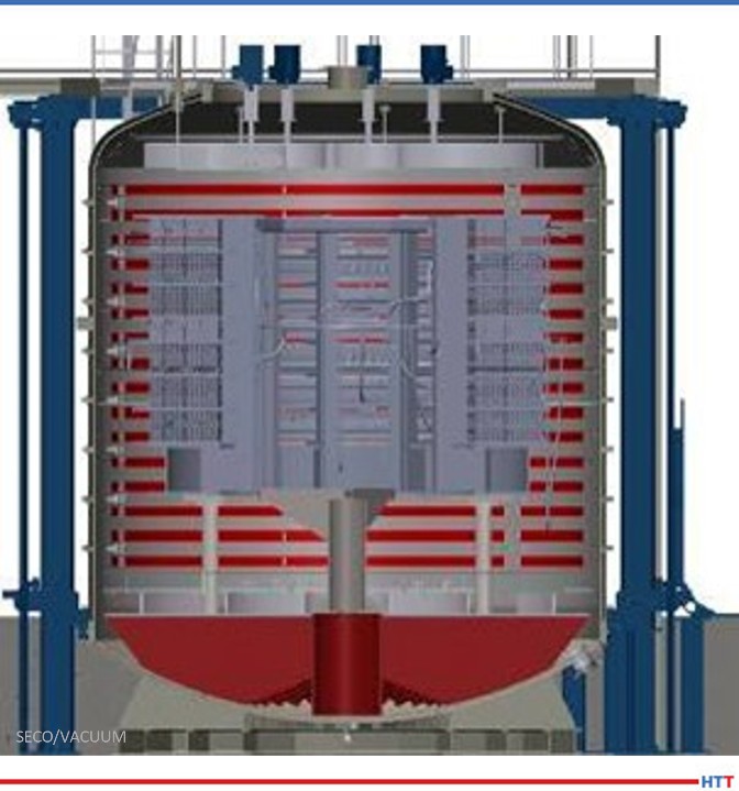
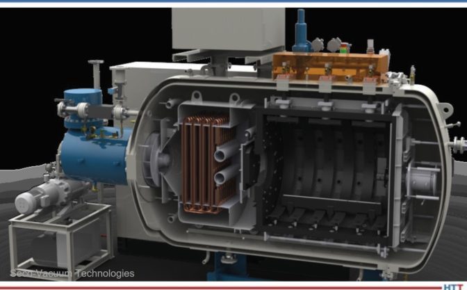
Figure 5. Cutaway illustration showing the furnace construction Source: SECO/VACUUM
There was no room for error. SECO/VACUUM collaborated with the engineers at General Atomic to create a heat treat furnace that can assure temperature variation within the coil never varies by more than 18°F (10°C) anywhere in the furnace at any time in the five-week cycle and achieves near-perfect repeatability for all seven modules.
They accomplished this with quadruple-redundant control thermocouples and feeding temperature data from 150 points in the coil into the control computers. To shield against impurities, the furnace is first evacuated to a vacuum pressure of 0.001 Torr, and then purged with pure argon to drive out any residual oxygen or hydrocarbons that could contaminate the purity of the superconductor. Monitoring the argon atmosphere for impurities are redundant mass spectrometers. The argon is circulated by seven convection fans to heat the solenoid assembly evenly. Each of these fans must be driven through ferrofluidic feedthrough seals which allow the rotating shafts to operate through the furnace walls without compromising the vacuum seal of the furnace.
Consult, Collaborate, and Partner with SECO/VISORY
General Atomics first began discussing this project with Rafał Walczak, the product manager at SECO/VACUUM, in early 2010. Both teams spent over two years on conceptual discussions, preliminary designs, and process simulations before SECO was even awarded the contract. Once SECO was on board, it took another two years of design, fabrication, and installation before the furnace could be put into operation. SECO/VACUUM built it to handle a lifetime of use without error so they could be sure that it would work flawlessly for the seven cycles that it actually had to run.
The SECO/VISORY Heat Treat Advisory Council is a team of SECO/VACUUM heat treat experts and consultants with diverse thermal experience and process knowledge who are available to help companies solve their specific heat treat equipment challenges.
About the Author: Rafal Walczak is the product manager at SECO/VACUUM. Rafal joined SECO/WARWICK Group as a service engineer in Vacuum Furnaces Division soon after graduation from Technical University of Zielona Góra in 2002. Since 2008, he has been involved in vacuum furnace sales in Europe and the USA. The combination of his technical background and field service experience help him provide outstanding support to his SECO/VACUUM customers. For more information, contact Rafal at Rafal.Walczak@SecoVacUSA.com.
Find heat treating products and services when you search on Heat Treat Buyers Guide.com
Want a free tip? Read some of the top 101 Heat TreatTips that heat treating professionals submitted over the last few years. These handy technical words of wisdom will keep your furnaces in optimum operation and keep you in compliance. If you want more, search for "101 heat treat tips" on the website! This selection features 5 tips all about the hearth of your furnace!
Also, check out Heat TreatResources in the September 2021 magazine to check it out yourself!
Hacksaw Your Hearth!
When loading parts, carefully place the workload on the center of the hearth (front-to-back and side-to-side). Make sure it is stable and no part of the load is close to or touching the heating elements. This can create arcing and damage your parts.
Tip: Once the load is in place, mark the hearth posts with a hacksaw to quickly find the front and back measurements each time.
(Ipsen USA)
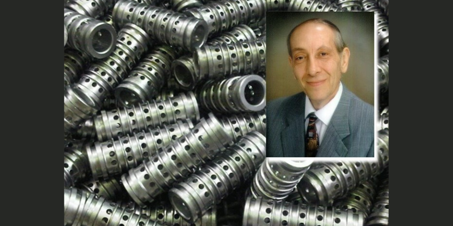
TZM Moly Grids
A very commonly observed failure mechanism with a moly post hearth assembly is bending of the moly posts. They will stay fairly straight at the center of the hearth area, but they can distort badly toward the outer sides of the work zone. The outer rows of vertical posts end up leaning away from each other. This is due to the very high linear thermal expansion coefficient of nickel-iron alloy grids (usually 330 SS or Inconel). With a high load on the nickel alloy grid, it is not able to slide on the perpendicular hearth beams as the temperature rises. The outer hearth post rows are forced in an outward direction. The quenching of the furnace load does not reverse all of this effect and over time results in the severe bending of the hearth posts.
Contact us with your Reader Feedback!
By replacing the stainless steel or nickel alloy grids with a moly or TZM alloy moly grid, which exhibits very low thermal expansion, the hearth life can be increased. For comparison, the figure shows the coefficients of linear thermal expansion for commonly used grid materials. For example, a 36” wide 330 SS grid at 70°F grows to 36.6” wide at 2200°F.
Another significant benefit of TZM moly grids is use at higher furnace process temperatures without the problem of a softened, sagging grid that cannot support the load properly.
(Grammer Vacuum Technologies, Inc.)
How to make thru-process temperature monitoring robot friendly!
In modern rotary hearth furnaces, temperature profiling using trailing thermocouples is impossible as the cables would wind up in the furnace transfer mechanism.
Due to the central robot loading and unloading and elimination of charging racks/baskets the use of a conventional thru-process system would also be a challenge.
Faced with such loading restrictions it is necessary to fit the thermal barrier inside the cavity of the product (engine block shown) and allow automated loading of the complete combined monitoring system and product.
To allow miniaturization of the thermal barrier to fit, but also provide sufficient thermal protection, the use of phased evaporation technology is critical. Such a system allowed BSN Thermoprozesstechnik GmbH in Germany to commission such a furnace accurately and efficiently and thereby optimize settings to not only achieve product quality but ensure energy efficient, cost effective production.
(PhoenixTM)
Hearth Height Adjustment
The available width and height of the work zone in a vacuum furnace with a round hot zone is determined by the elevation placement of the top of the furnace hearth. This distance is determined by the length of the vertical hearth support posts. By having spare, interchangeable hearth post sets of varying lengths, one can extend the work zone width or height as needed. The figure shows a variety of work zone dimensions that are possible with a standard 36” wide x 36” tall typical work zone as an example. The important thing in choosing your work zone shape is to maintain an (approximately) 3” clearance between the elements and the work zone to avoid part to element contact.
Note: With the symmetric shapes of modern, round hot zones there is good reason to expect good temperature uniformity anywhere within the 3” clearance ring shown in Figure 1. If you can build a survey fixture capable of surveying all the space you want to use, you theoretically could use more than just the rectangular space shown in the examples. Getting an auditor to accept the survey is a separate task.
(Grammer Vacuum Technologies, Inc.)
TZM Moly Hearths
In the case of furnaces with all-molybdenum hearths or of graphite hearths with molybdenum (“moly”) support posts, a direct replacement of those moly posts with TZM alloy moly posts will both increase strength of the hearth assembly and eliminate problems with recrystallization-induced embrittlement of the posts. (For an all-moly hearth, replacement of the horizontal load beams with TZM would have a similar benefit.) The comparative strengths vs. temperature of TZM alloy and pure moly are shown in the graph. Whereas at room temperature the strengths are very similar (around 110KSI-120KSI), once you exceed the 2000F recrystallization temperature of pure moly, the difference becomes dramatic. At 2000F the pure moly is about 40% of the strength of TZM alloy. By the time it reaches 2300F the pure moly is only about 25% of the strength of TZM alloy.
Not only is the TZM alloy much stronger than pure moly at temperature, but it also does not suffer from the same embrittlement problems. Pure moly, once it has recrystallized, forms very brittle grain boundaries in its microstructure. Its behavior begins to resemble that of glass. This is the primary mode of failure of moly components in vacuum furnaces – breakage due to intermetallic grain boundary embrittlement. TZM’s recrystallization temperature is around 2500F, and even when it does recrystallize, it forms very fine new grains that still have decent ductility. Hence, we recommend TZM alloy as a replacement for pure moly in all structural applications for vacuum furnaces. It is the “right stuff.”
Note that all metals used in a vacuum furnace, moly and TZM alloy included, will suffer from distortion due to the numerous thermal cycles they experience. Moly hearth beams are a good example. Once distorted moly hearth beams can be very difficult if not impossible to straighten without breaking them. To have any chance at all they must be heated to forging temperatures. TZM hearth beams however, due to their good ductility can often be heated to forging temperatures and successfully straightened. Most heat treating shops scrap out the moly hearth beams rather than even trying to straighten and re-use them. With a TZM hearth the hearth components can typically be re-used with a newly re-lined hot zone saving a large additional expense.
(Grammer Vacuum Technologies, Inc.)
Check out these magazines to see where these tips were first featured:
Find heat treating products and services when you search on Heat Treat Buyers Guide.com
Part discoloration after vacuum heat treating? What can heat treaters do to prevent this? In this best of the web, Q&A-style article, witness the heat treating industry gather around to exchange ideas and find a solution to the problem. Part position, backfill gas level, contaminated quench gas, or an air leak could all be to blame in this Technical Tuesday.
Dan Herring weighs in on the issue as well. To read The Heat Treat Doctor's®diagnosis, click the link below. Learn how the color and position of the discoloration give clues as to the source of the problem.
An excerpt:
"So, what else could be happening? Let The Doctor add a few thoughts to the discussion. First, the fact that the discoloration (staining) is brown in coloration suggests that the oxide is forming on the part surface during cooling when the temperature is in the range of (approximate) 245ºC – 270ºC (475ºF – 520ºF). This is supported by the fact that the oxidation does not occur “during natural cooling” (which we assume to mean cooling under vacuum). Second, the fact that the discoloration is more evident at the bottom of the load suggests the phenomenon is (gas exposure) time dependent, that is, the longer the parts take to cool through the critical range, the greater the chance for discoloration."
Ever heard of binder jetting (BJT)? It's an evolving technology that is quickly catching up to metal injection molding (MIM). Compared to MIM, BJT has a lower cost per part rate, produces larger parts, and, because BJT is a cold process, it does not introduce residual stress inside the part.
Even though BJT is a cold process, sintering is a key step in BJT. Read this best of the web article to learn the ins-and-outs of sintering with binder jetting.
An excerpt:
"Vacuum sintering furnaces are usually the go-to choice for sintering of [binder jetting] parts, thanks to the ability to provide bright and shiny sintered parts, the tight process parameters control and the possibility to work with different debinding and sintering atmospheres."
There is no way to validate the heat treating process without completely destroying the job. Here’s where pyrometry becomes crucial. The precision, accuracy, and uniformity standards of specifications like AMS2750 and CQI-9 provide peace of mind without destructive testing. Read how the requirements of these regulations are benefiting the industry through standardization and defect prevention.
"El tratamiento térmico como la mayoría de los procesos especiales, tiene la particularidad de ser una operación crítica que para su validación requiere de pruebas destructivas. . . "
Read the English translation of this article by Víctor Zacarías, general director at Global Thermal Solutions Mexico, in the version below, or the Spanish translation when you click the image to the right.
Both Spanish and English translations of the article were originally published in Heat Treat Today's March 2022 Vacuum Furnace print edition.
Víctor Zacarías General Director Global Thermal Solutions Mexico
Introduction
Heat treatment operations are generally perceived as black boxes whose results are not very predictable. Although we understand the physical mechanisms involved in modifying the properties of a certain material, heat treatment furnaces are thermodynamically imperfect, and sometimes the final results are too.
An extra variable must be added to this picture. As the properties of the final product can only be validated through destructive testing, we must have a high level of process control in place if we want to ensure repeatability in heat treat operations. This is where pyrometry specifications play an important role, particularly in defining the correct temperature controls for consistent heat treatment.
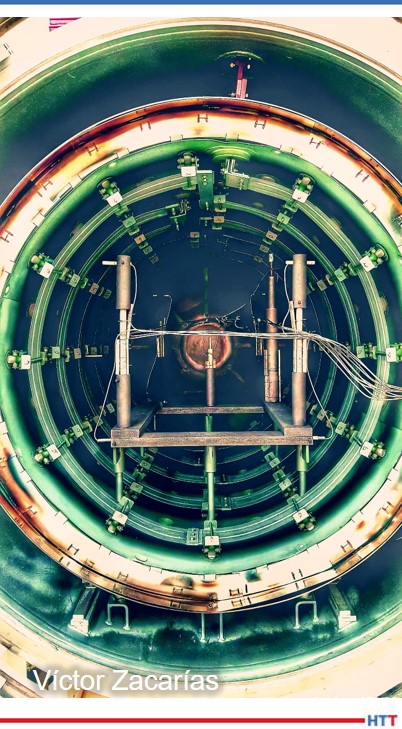
Picture 1. Temperature uniformity survey performed in a vacuum furnace
Pyrometry standards/specifications define the temperature control requirements for thermal processing equipment used in heat treatment operations (furnaces, ovens, muffles, etc.). These specifications are very comprehensive documents that allow us to solve the following problems:
How do you know that the temperature readings are accurate?
How do you know the temperature variation of your measurement system?
How do you know that the entire load was exposed to a consistent temperature during the cycle?
How do you know what you know? (Documented evidence)
The most widely accepted and proven pyrometry specifications in the industry are:
AMS2750: issued by SAE International, it is the universally accepted standard for thermal processing certification purposes in the aerospace industry (Nadcap).
AIAG CQI-9: this assessment provides the pyrometry requirements for the evaluation of heat treatment in the automotive industry.
API 6A & 16A: annexes establish the pyrometric requirements for the components treated in the energy industry (oil and gas).
All of these specifications describe in their content at least the following four items:
Calibration of thermocouples (or any other temperature sensor), as well as the limit of use depending on its
application
Calibration of control and test instrumentation
The procedure and acceptance criteria for conducting a System Accuracy Test (SAT)
The method and acceptance criteria for a Temperature Uniformity Survey (TUS)
These specifications are subject to continuous revisions to ensure that the requirements are understood. However, it does not change the fact that they are very extensive documents, generally misinterpreted and which require experienced personnel for their implementation. As an example of these difficulties, in Nadcap accreditation audits, eight out of 10 findings are directly related to pyrometry. CQI-9 assessments in the automotive industry show similar figures.
Despite the above, the right implementation of the pyrometry requirements has proven for years that a consistent heat treatment process can be achieved, providing data that allows defect prevention in an effective way.
Thermocouple Requirements
A thermocouple is a very simple temperature sensor that consists of two conductors with different thermoelectric characteristics. The conductors are joined at one end (hot junction) which will be in contact with the element whose temperature is to be measured. When the conductors are exposed to a temperature gradient, a difference of electrical potential (mV) is generated due to the phenomenon known as Seebeck effect. At the other end (cold junction), a voltmeter is used to measure the potential generated by the temperature difference between the two ends (See Figure 1).
Figure 1. Schematic of a thermocouple
Pyrometry standards defi ne the calibration requirements for the thermocouples used in thermal processing equipment. In order to acquire thermocouples in accordance with these regulations, we must consider the final use of the sensor to define the maximum error allowed at the time of calibration (See Table 1).
Once we have a calibrated thermocouple, the date of the installation must be documented to track the sensor life. Thermocouples have a finite lifetime because of the natural degradation of the materials of which they are made, leading to a decrease in their accuracy. Therefore, the replacement of temperature sensors must be calendarized depending on the thermocouple type and the temperature to which they are exposed.
Instrumentation Requirements
Instruments receive electrical communication from thermocouples and convert potential (mV ) to a usable format.
Pyrometry specifications like AMS2750 and CQI-9 define the resolution and accuracy requirements for the instrumentation used in heat treating equipment, as well as the frequency at which these instruments must be calibrated. The level of accuracy of the instrumentation is based on the applicable specification and the purpose of the instrument, as shown in Table 1.
Table 1. Accuracy required for temperature sensors according to AMS2750 and CQI-9
It is important to consider the manufacturer’s instructions when installing and calibrating control and recording instruments. From a metrological standpoint, documentation must evidence that the calibrations are traceable to a national reference standard (NIST, CENAM, etc.) and, in most industries, carried out in accordance with ISO/IEC 17025.
The System Accuracy Test
A System Accuracy Test (SAT) or probe check is a very simple test to ensure that the entire measurement system (thermocouple and instrument together) provides an accurate representation of the temperature. It is an on-site comparison of the furnace’s measurement system against an independent calibrated measurement system (See Figure 2). The purpose of this test is to determine if the natural deviation of the temperature measurement system is still acceptable.
Figura 2. Diagrama de un Ensayo de Exactitud del Sistema (SAT)
The criteria to determine whether the results of an SAT test are acceptable or not will depend on the applicable regulations, AMS2750 or CQI-9. If the difference in the SAT exceeds the limits allowed by the standard, internal procedures must take into account the following considerations before reprocessing parts:
Document that the equipment has failed a test
Determine the root cause of the failure
Implement corrective actions
When an SAT test result fails, corrective actions can generally be reduced to two options: replace the thermocouple and/or recalibrate and adjust the instrument.
A SAT is performed to assure the accuracy of all the systems in the furnace which are used to make decisions about the product, both control and recording. It is important to note that SAT test results change over time, therefore historic SAT data is very useful to identify trends and proactively take action before a deviation shows.
Temperature Uniformity Surveys
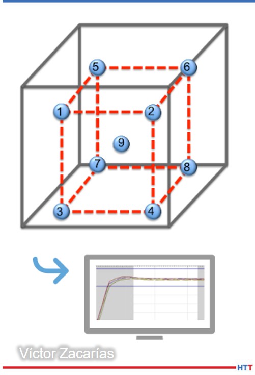
Figure 3. Schematic of a temperature uniformity survey (TUS)
A Temperature Uniformity Survey (TUS) is a test where a calibrated instrument (data logger) and several calibrated thermocouples measure the temperature variation inside the furnace. The result of a TUS test indicates where the hottest and/or coldest spots are in a furnace and provides elements to determine how to correct them.
For most commercially available furnace volumes, TUSs are conducted introducing nine thermocouples for batch type furnaces, and three tracking thermocouples for continuous furnaces.
A TUS is considered acceptable if the test thermocouple readings are within the limits set by the specification for the required time. TUS is highly recommended to be performed after the initial installation of the equipment or after a modification that could alter the heating characteristics of the furnace. Subsequently, they must be carried out periodically in accordance with the applicable regulation.
Importance of Pyrometry
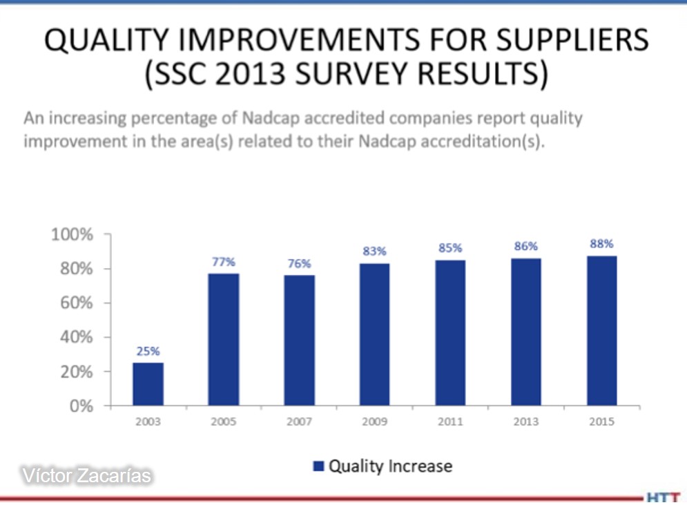
The labor of harmonizing special processes is not easy. However, there is strong evidence that proves the effectiveness of this eff ort. For example, Supplier Technical Assistance teams at Ford Motor Co. have followed the results achieved by the implementation of CQI-9 by their suppliers and have estimated cost savings of up to 20 million dollars in reduction of heat treatment defects. Similarly, the Performance Review Institute, which is the organization in charge of managing Nadcap, reports increasingly positive results each year by the implementation of the program, impacting directly on continuous improvement of aerospace organizations that accredit it (Figure 4).
Figure 4. Perception in quality improvement from Nadcap audits
Pyrometry testing provides valuable information that encourages preventive maintenance of furnaces and related equipment. At the same time, it provides understanding of the measurement systems that allow achieving repeatable metallurgical results. In both cases, the information generated in pyrometry allows heat treaters to reduce scrap and quality claims and most importantly, ensures business continuity by showing compliance with customers’ requirements.
About the author: Víctor Zacarías is a metallurgical engineer from the University of Querétaro with studies in Strategic Management from Tec de Monterrey. With over 15 years of experience in heat treatment management, he is currently the managing director of Global Thermal Solutions México. Victor has conducted numerous courses, workshops, and assessments in México, United States, Brazil, Argentina, and Costa Rica and has been a member of the AIAG Heat Treat Work Group (CQI-9 committee).
There is no way to validate the heat treating process without completely destroying the job. Here’s where pyrometry becomes crucial. The precision, accuracy, and uniformity standards of specifications like AMS2750 and CQI-9 provide peace of mind without destructive testing.
Read the Spanish translation of this article by Víctor Zacarías, director general de Global Thermal Solutions México, in the version below, or read both the Spanish and the English translation of the article where it was originally published: Heat Treat Today's March 2022 Vacuum Furnace print edition.
El tratamiento térmico como la mayoría de los procesos especiales, tiene la particularidad de ser una operación crítica que para su validación requiere de pruebas destructivas. Al no poder medir el 100% del producto, las normas de pirometría juegan un papel fundamental en el control y documentación de los procesos de tratamiento térmico. La norma AMS2750 y la evaluación CQI-9 son los estándares mas aceptados en la industria aeroespacial y automotriz respectivamente, y describen los requisitos de precisión, exactitud y uniformidad para los sistemas de medición de temperatura y los equipos empleados en el procesamiento térmico. Este artículo sintetiza los requerimientos de estas normativas e ilustra los beneficios en la industria de contar con un enfoque homologado para la reducción de la variación y la prevención de defectos.
Víctor Zacarías Director General Global Thermal Solutions México
Introducción
Las operaciones de tratamiento térmico son percibidas generalmente como cajas negras cuyos resultados son poco predecibles. Si bien, entendemos los mecanismos físicos involucrados para modificar las propiedades de un material, los hornos de tratamiento térmico son sistemas termodinámicamente imperfectos, y por ende los resultados finales en ocasiones también lo son.
A esta situación hay que agregar una variable adicional. Al tratarse de operaciones en las cuales las características del producto final solamente pueden ser validadas a través ensayos destructivos, debemos de contar con un nivel particular de control de proceso si queremos asegurar la repetibilidad en las operaciones de tratamiento térmico.
Fotografía 1. Ensayo de uniformidad de temperatura conducido en horno de vacío
Las normas y especificaciones de Pirometría definen los requerimientos de control de temperatura para los equipos de procesamiento térmico (hornos, muflas, estufas, etc) empleados en las operaciones de tratamientos térmicos. Se trata de estándares muy completos que nos permite resolver las incógnitas que los auditores de proceso ponemos sobre la mesa
¿Cómo sabes que las lecturas de temperatura de tu horno son precisas?,
¿Cómo sabes cuál es la variación de temperatura de tu sistema de medición?
¿Cómo sabes que la totalidad de la carga fue expuesta a una temperatura consistente durante el ciclo completo de tratamiento térmico?,
¿Cómo sabes que lo sabes?
Las especificaciones de pirometría mayormente aceptadas y probadas en la industria son:
AMS2750, emitida por SAE International, es la norma universalmente aceptada para fines de certificación de procesamiento térmico en la industria aeroespacial
CQI-9 de la Automotive Industry Action Group (AIAG). Las secciones 3.1, 3.2, 3.3 y 3.4 definen los requerimientos de pirometría para la evaluación de tratamientos térmicos en la industria automotriz y
API 6A y 16A, cuyos anexos establecen los requisitos pirométricos para los componentes tratados en la industria de energía (oil & gas)
Todas estas especificaciones contemplan en su contenido al menos los siguientes 4 aspectos:
Calibración de los termopares (o cualquier otro sensor de temperatura), así como los requisitos y tiempo límite de uso en función de su aplicación.
Calibración de la instrumentación de control y prueba
El procedimiento y los criterios de aceptación para la realización de la prueba System accuracy Test (SAT).
El método y los criterios de aceptación para la prueba de uniformidad de temperatura o Temperature Uniformity Survey (TUS).
Las normas de pirometría son sometidas procesos de revisión profunda de manera frecuente por las organizaciones que las emiten para asegurar que los requerimientos sean entendidos. Sin embargo, no cambia el hecho de que se trata de documentos complejos, generalmente malinterpretados y que requieren de personal experimentado para su implementación. Cómo ejemplo de estas dificultades, en auditorías de certificación Nadcap (industria aeroespacial) 8 de cada 10 hallazgos levantados están relacionados directamente con pirometría. Las evaluaciones de CQI-9 en la industria automotriz presentan cifras similares.
A pesar de lo anterior, la implementación correcta de los requerimientos de pirometría ha probado por años que se puede alcanzar un proceso de tratamiento térmico consistente y arrojar datos que permiten prevenir defectos de manera efectiva.
Termopares
Un termopar es un sensor de temperatura que consiste de dos conductores con características termoeléctricas distintas. Los conductores están unidos en un extremo (unión de medición o hot junction), el cual estará en contacto con el elemento cuya temperatura se quiere medir. Cuando los conductores se exponen a un gradiente de temperatura se genera una diferencial de potencial (mv) debido al fenómeno conocido como Efecto Seebeck. En el otro extremo (cold junction), se empleará un voltímetro para medir el potencial generado por la diferencia de temperatura entre los dos extremos (ver figura a continuación).
Figura 1. Diagrama de un termopar
La normas de pirometría definen los requisitos de calibración para los termopares usados en el equipo de procesamiento térmico. Para adquirir termopares acordes con la normatividad, debemos considerar la aplicación final del sensor para definir el error máximo permitido al momento de la calibración (ver tabla a continuación).
Una vez que contamos con termopares calibrados, se debe documentar la fecha en la que se realiza la instalación para monitorear el tiempo de vida del sensor. Los termopares tienen un tiempo de vida finito debido a que la exposición a la temperatura provoca la degradación de los conductores y por ende la disminución de su precisión. El reemplazo por lo tanto de un sensor de temperatura estará determinado por el tipo de temopar (K, N, E, T, J, B, R, o S) y la temperatura a la que se expone.
Instrumentación
Los instrumentos reciben comunicación eléctrica de los termopares y convierten fuerza electromotriz (fem) a un formato usable.
La especificaciones de pirometría como AMS2750 y CQI-9 definen los requisitos de resolución y precisión para la instrumentación empleada en Tratamientos Térmicos, así como la frecuencia a la que se deben calibrar dichos instrumentos. El nivel de precisión de la instrumentación está en función la norma aplicable y el propósito del instrumento como se muestra en la siguiente tabla.
Tabla 1. Precisión requerida sensores de temperatura de acuerdo a AMS2750 y CQI-9
Es importante considerar las instrucciones del fabricante al momento de instalar y calibrar los instrumentos de control del horno. Desde el punto de vista metrológico, la documentación debe demostrar que la calibración de los equipos es trazable a un patrón nacional (NIST, CENAM, etc) y, en la mayoría de los casos, realizada de conformidad a la norma ISO/IEC 17025:2017 correspondiente a los laboratorios de ensayo y calibración.
Prueba de Exactitud del Sistema (System Accuracy Test o Probe Check)
La prueba System Accuracy Test (SAT) o Probe Check es una comparación en sitio del sistema de medición del horno contra un sistema de medición calibrado. El objetivo de esta prueba es determinar si la desviación natural del sistema de medición de temperatura se encuentra dentro de límites aceptables.
Figura 2. Diagrama de un Ensayo de Exactitud del Sistema (SAT)
El criterio de aceptación para determinar si los resultados de una prueba SAT son aceptables o no, dependerá de la normativa aplicable. Si la diferencia del SAT excediera los límites permitidos por la norma, los procedimientos internos deben tomar en cuenta la siguientes consideraciones antes de volver a procesar piezas:
Documentar que el equipo ha fallado la prueba,
Determinar la causa raíz de la falla y
Implementar acciones correctivas
Cuando el resultado de la prueba SAT excede los límites permitidos, las acciones correctivas generalmente se pueden reducir a dos alternativas: (1) Reemplazo del termopar o (2) Recalibración y ajuste del instrumento.
Una vez aplicadas las acciones correctivas y, antes de procesar cualquier material adicional, la prueba SAT debe repetirse conforme al procedimiento de la norma para confirmar la efectividad de las acciones correspondientes.
Un SAT es una prueba muy simple para asegurar que el todo el sistema de medición (termopar mas instrumento en conjunto) provee una representación exacta de la temperatura. Es importante tomar en cuenta que los resultados de la prueba SAT cambian con el tiempo, por lo tanto se trata de un chequeo muy útil para identificar tendencias y tomar acciones de manera proactiva antes de una desviación.
Prueba de Uniformidad de Temperatura (Temperature Uniformity Survey)
Figura 3. Diagrama de un Ensayo de Uniformidad de Temperatura (TUS)
Un Temperature Uniformity Survey (TUS) es una prueba en donde un instrumento y varios termopares calibrados miden la variación de temperatura dentro del volumen de trabajo del horno. La prueba TUS indica dónde se encuentran los puntos mas fríos y/o calientes de un horno y proporciona elementos para determinar el porqué de esos puntos y cómo corregirlos.
El primer aspecto a considerar es la cantidad de termopares a emplear durante la prueba, que está en función del volumen de trabajo del horno y la normativa aplicable. Para la mayoría de los volúmenes de los hornos disponibles comercialmente, la cantidad de termopares requeridos es de 9 para hornos tipo batch (lote) y 3 para hornos continuos.
Un TUS se considera aceptable si las lecturas de los termopares se encuentran dentro de los límites establecidos por la especificación durante el tiempo requerido en todo momento. La prueba TUS se recomienda realizar después de la instalación inicial del equipo o después de una modificación que pudiera alterar las características de uniformidad del horno. Posteriormente se deben realizar de manera periódica de acuerdo a la normativa.
Importancia de la pirometría
La labor para armonizar los procesos especiales no es sencilla, sin embargo existen datos contundentes que prueban la efectividad de este esfuerzo. El equipo de STAs de Ford Motor Co. ha realizado estimaciones de los beneficios obtenidos al implementar CQI-9 en su cadena de proveduría y han cuantificado ahorros de hasta 20 millones de dolares por conceptos de reducción de defectos en Tratamientos Térmicos. De igual manera, el Performance Review Institute, quien es la organización encargada de administrar el programa Nadcap, reporta cada año el impacto en la mejora continua en las organizaciones aeroespaciales que acreditan este programa.
Figura 4. Percepción de la mejora en la calidad en relación con su acreditación Nadcap
Las pruebas de pirometría proporcionan información valiosa que fomenta el mantenimiento preventivo de los hornos y equipos relacionados. Al mismo tiempo, el entendimiento y control de los sistemas de medición ayudan de manera proactiva a obtener resultados metalúrgicos repetibles. En ambos casos la información generada en estas pruebas nos permite reducir la probabilidad de scrap o reclamos de calidad y asegurar la continuidad del negocio al mostrar conformidad con los mandatos del cliente.
Sobre el autor: Víctor Zacarías es ingeniero metalúrgico egresado de la Universidad Autónoma de Querétaro con estudios en Gerencia Estratégica por parte del Tec de Monterrey. Con más de 15 años de experiencia en la gestión de tratamientos térmicos, actualmente es director general de Global Thermal Solutions México. Víctor ha realizado numerosos cursos, talleres y evaluaciones en México, Estados Unidos, Brasil, Argentina y Costa Rica y ha participado en el Grupo de Trabajo de Tratamiento Térmico de AIAG (CQI-9) y en el Comité de Ingeniería de Materiales Aeroespaciales de SAE.
There is an age-old adage that exists in the heat treating world. That supposition states that “the smaller the vacuum furnace, the faster it will quench.” Is this adage true? Explore Solar Atmospheres’ journey as they designed an experiment to discover if pressure or velocity most affects cooling performance.
This Technical Tuesday was written by Robert Hill, FASM, president, and Gregory Scheuring, plant metallurgist, both from Solar Atmospheres. The article originally appeared inHeat TreatToday’sMarch 2022 Aerospace Heat Treating print edition.
Introduction
Our study compared the cooling rates of two distinctly sized High Pressure Gas Quenching (HPGQ) vacuum furnaces — a large 10-bar vacuum furnace equipped with a 600 HP blower motor versus a smaller 10-bar vacuum furnace equipped with a 300 HP motor. Both furnaces, one with a 110 cubic feet hot zone, the other with a 40 cubic feet hot zone, were exclusively engineered and manufactured by Solar Manufacturing located in Sellersville, PA.
History
High Pressure Gas Quenching in the heat treatment of metals has made tremendous strides over recent years. Varying gas pressures within the chamber have been shown to be more governable than their oil and water quenching counterparts. The number one benefit of gas cooling versus liquid cooling remains the dimensional stability of the component being heat treated. In addition, using gas as a quench media dramatically mitigates the risk of crack initiation in a component. This is primarily due to the temperature differentials during cooling. Gas quenching cools strictly by convection. However, the three distinct phases of liquid quenching (vapor, vapor transport, and convection) impart undue stress into the part causing more distortion (Figure 1).
Figure 1. Three phases of liquid quenchants Source: Solar Atmospheres
There are multiple variables involved with optimizing gas cooling. These include the furnace design, blower designs, heat exchanger efficiency, gas pressure, gas velocities, cooling water temperatures, the gas species used, and the surface area of the workpieces. Whenever these variables remain constant, the relative gas cooling performance of a vacuum furnace typically increases as the volume of the furnace size decreases.
The Furnace
Solar Manufacturing has built multiple high pressure gas quenching furnaces of varying sizes over the years ranging from 2 to 20-bar pressure. We have learned that vacuum furnaces, rated at 20-bar and above, became restrictive in both cost constraints and diminishing cooling improvements. Therefore, Solar Manufacturing engineers began to study gas velocities to improve cooling rates. They determined increasing the blower fan from 300 HP to 600 HP, along with other gas flow improvements, would substantially increase metallurgical cooling rates. The technology was reviewed and determined to be sound. A 48” wide x 48” high x 96” deep HPGQ 10-bar furnace, equipped with this newest technology, was purchased by Solar Atmospheres of Western PA located in Hermitage, PA.
Image 1. HFL50 furnace (36” x 36” x 48”)
Source: Solar Atmospheres
Image 2. HFL74 furnace (48” x 48” x 96”) Source: Solar Atmospheres
The Test
Image 3. Test load with thermocouple placement Source: Solar Atmospheres
Once this new vacuum furnace was installed, a cooling test was immediately conducted. A heavy load would be quenched at 10-bar nitrogen in an existing HFL 50 sized furnace (36” x 36” x 48”). The same cycle was repeated in the newly designed vacuum furnace almost three times its size! (Images 1 and 2).
The load chosen for the experiment was 75 steel bars 3” OD x 17” OAL weighing 34 lbs each. The basket and grid system supporting the load weighed 510 lbs. The total weight of the entire load was 3060 lbs. Both test runs were identically thermocoupled at the four corners and in the center of the load. All five thermocouples were deeply inserted (6" deep) into ¼" holes at the end of the bars (Image 3). Each load also contained two 1" OD x 6" OAL metallographic test specimens of H13 hot working tool steel. These specimens were placed near the center thermocouple to ensure the “worst case” in terms of quench rate severity. All tests were heated to 1850°F for one hour and 10-bar nitrogen quenched.
Results
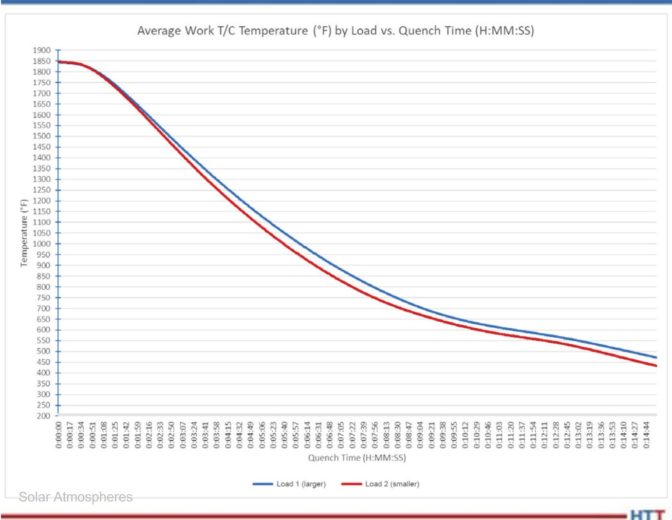
The comparative cooling curves between both HPGQ vacuum furnaces are shown in Chart 1. Table 1 reveals that in the critical span of 1850°F to 1250°F for H13 tool steel, the cooling rate in the larger furnace with more horsepower nearly matched the cooling rate of the furnace three times smaller in size.
Table 1. Critical cooling rates for H13 (1850°F –1250°F) Source: Solar Atmospheres
Chart 1. Average quench rate for five thermocouples Source: Solar Atmospheres
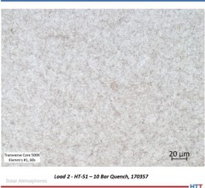
Micrographs of the H13 test specimens processed in each load were prepared (Images 4 and 5). The microstructure of each test specimen is characterized by a predominantly tempered martensitic microstructure with fine, undissolved carbides. The consistency of the microstructure across both trial loads further demonstrates that while the larger furnace utilized the higher horsepower, both resulted in a critical cooling rate sufficient to develop a fully martensitic microstructure.
These tests prove that the greatest impact on the cooling performance in a vacuum furnace is to increase the gas velocity within that chamber. This was achieved primarily by increasing the horsepower of the blower fan. By doing this, the ultimate cost to the customer is significantly less than manufacturing a higher pressure coded vessel. This newly designed vacuum furnace has proven to be a game changer.
Part II of this article will discuss real life case studies and how both Solar and Solar’s customers have mutually benefited from this newest technology.
About the Author:
Robert (Bob) Hill, FASM President Solar Atmospheres of Western PA Source: Solar Atmospheres
Robert Hill, FASM, president of Solar Atmospheres of Western PA, began his career with Solar Atmospheres in 1995 at the headquarters plant located in Souderton, Pennsylvania. In 2000, Mr. Hill was assigned the responsibility of starting Solar Atmospheres’ second plant, Solar Atmospheres of Western PA, in Hermitage, Pennsylvania, where he has specialized in the development of large vacuum furnace technology and titanium processing capabilities. Additionally, he was awarded the prestigious Titanium Achievement Award in 2009 by the International Titanium Association.
Time to evacuate! When it comes to evacuating atmospheric pressure from vacuum furnace chambers, the addition of a diffusion pump can help attain a lower system pressure than the typical roughing pump and vacuum booster pump allow.
This best of the web article identifies the basics of vacuum furnace pumps and then explains how diffusion pumps in particular work and identifies a few considerations to think about to determine if you need this addition or not.
An excerpt:
"For the diffusion pump to function properly, the main and foreline valves must be open, allowing the furnace to operate in high vacuum. Fluid at the bottom of the pump is heated to boiling and forced up through the center of the jet assembly."


 If you like to read about how heat treaters can be game changers in multinational science projects, this is the article for you. A specially designed vacuum heat treat furnace was commissioned to heat treat critical components in a large energy generator. The heat treating of these components takes 5 weeks to complete; talk about a long, uniform heat treat period.
 Find heat treating products and services when you search on Heat Treat Buyers Guide.com