VACUUM FURNACES TECHNICAL CONTENT

10 Heat Treat Tips: Vacuum Furnaces

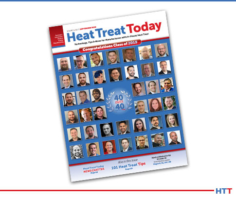
Heat Treat 2019 is coming, and one of the great benefits of gathering with a community of heat treaters is the opportunity to challenge old habits and look at new ways of doing things. Heat Treat Today’s 101 Heat Treat Tips is another opportunity to learn the tips, tricks, and hacks shared by some of the industry’s foremost experts. The inaugural list of 101 Heat Treat Tips was published in the FNA 2018 Special Print EditionThis special edition is available in a digital format here.
Today's Technical Tuesday features 10 Tips -- all from the Vacuum Furnaces category and all supplied by the same equipment manufacturer.

Heat Treat Today is compiling the 2019 101 Heat Treat Tips list for the fall issue to be distributed at Heat Treat 2019, the biennial show from the ASM Heat Treating Society to be held in Detroit, Michigan, October 14-17, 2019. If you have a heat treat-related tip that would benefit your industry colleagues, you can submit your tip(s) to doug@heattreattoday.com or editor@heattreattoday.com.


Heat Treat Tip #24

Dirt In, Dirt Out!

Parts going into the furnace should be as clean as possible. Avoid placing parts in the furnace that contain foreign object debris (FOD). FOD on work surfaces going into the furnace will contaminate the furnace and the parts themselves. Dirty work in, dirty work out. FOD comes in many forms. Most common: oil, grease, sand in castings or grit blasting operations, and metal chips that generally originate from the manufacturing process before the parts are heat treated. It could also be FOD from the shipping process such as wood or plastic containers used to ship the parts.


Heat Treat Tip #26

Solenoid valves could be the problem if helium detection fails.

When a Helium Leak Detector Doesn't Help

If an air leak cannot be found with a helium mass spectrometer, take apart the gas backfill or partial pressure solenoid valves to ensure they are clean. A small piece of debris can cause a valve to leak a process gas into the furnace that will not be found with a leak detector. Debris is often found in the valve seats when piping to the valve was disturbed in some way such as new piping or repair that stirs up contaminants in the line.


Heat Treat Tip #46

O2 Analyzer Helps Ensure Gas Purity

In addition to monitoring dewpoint at the farthest location from the gas source in your heat treat facility, an oxygen analyzer is also recommended as an additional tool for monitoring gas purity. Generally, the analyzers used to measure dew point drift low over time. One may think they have a very low dew point gas, however, it could be the dew point analyzer is beginning to fail. Quarterly checks of the dew point analyzer's accuracy should be taken; some OEMs recommend replacing the sensors annually. Oxygen analyzers provide a more stable reading over a period of time and build redundancy in confirming gas purity when coupled with the dew point analyzer.


Heat Treat Tip #48

Seal Threaded Connections

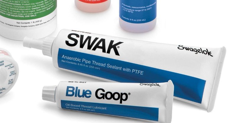
SWAK from Swagelok is a great thread sealing option. (photo source: LinkedIn)

Ensure threaded connections have adequate sealing protection on them to prevent air leaks through the threads where applicable. Wipe off excess sealant once the connection is made.

  1. SWAK from Swagelok is excellent
  2. Apply to the male threads only, not on any other surface as it could contaminate the system the component is being installed on.
  3. Excess SWAK can be removed with a solvent such as acetone
  4. Finger tight first, then tighten with a wrench
  5. After the sealant is dry (recommend 24hrs by manufacturer) do not loosen as this could break the seal once cured.

Heat Treat Tip #61

Start With the Obvious

When a problem arises with the furnace, always start the troubleshooting process with the last item that was worked on. Start with the obvious; don't look for a needle in the haystack. For example, if the furnace will not pump into high vacuum and maintenance was just performed on the furnace with the pneumatic pressure valves being shut to perform that maintenance operation, the pneumatic valve to the main poppet valve on the diffusion pump may not have been re-opened, causing the diffusion pump main poppet valve to not open.


Heat Treat Tip #74

Make Sure Your Gas Meets Spec

Ensure each delivery of process gas is accompanied by a certification identifying purity, oxygen content, and dew point. For example, nitrogen should be 99.998% pure, 10 ppm oxygen max, and a dewpoint no higher than -89°F. With contaminated gas or gas that does not meet the criteria above, parts processed in the furnace and subjected to the partial pressure of the gas or quenched with the gas may also become contaminated, typically in form of oxidation and/or decarburization. Generally varying purity is not a concern, however, the specific purity of the gas required needs to be conveyed to the gas supplier and a certification supporting the gas type you ordered was delivered. An accompanying certification by the gas supplier goes a long way in audits and other disputes.


Heat Treat Tip #76

Specification Checklist for Vacuum Furnace Purchase

If you're planning on purchasing a new vacuum furnace, create a technical specification for the manufacturer(s) that clearly outlines the performance, functions, and accessories required on the furnace. The specifications should be reviewed by multiple departments including but not limited to engineering, quality, production, and management.

  1. List of department sign-offs required (engineering, production, maintenance, quality)
  2. Applicable documents required (i.e., AMS2750E, AMS2769)
  3. List of parameters to be recorded (temperature, pressure, flow rate, etc.)
  4. List of required alarms
  5. Physical location of furnace and associated components such as control system and surge tank
  6. Units of measurement (°F or °C, torr or Pascals, minutes or hours)
  7. How many process gases and what type
  8. Cooling rate requirements (This will help decide what quench pressure design furnace is required, for example, 2 bar or 10 bar.)
  9. How many work thermocouples are required
  10. What pre-testing verification is required for final acceptance. For example, thermal uniformity survey temperature points and tolerances, vacuum pump downtime and levels, leak up requirements, quench tests, process validation tests.

Wipe both door flanges and O-ring every time.

Heat Treat Tip #84

Clean the Door—Every Time!

Wipe down the front door O-ring and both flanges every time before the door is closed to ensure there is no debris on the O-ring or flange. Over time, the debris will damage the O-ring and pit the flange causing sealing issues.


Heat Treat Tip #91

Include Maintenance Team in New Vacuum Purchase Process

Include the maintenance manager in any furnace purchase decision. The manager and team are the ones tasked with troubleshooting, repair, and preventative maintenance. The maintenance manager will make sure the furnace has clear access for maintenance and replacement of major components including vacuum pumps, cooling motor, hot zone, and heat exchanger. The longer it takes to repair the furnace, the more downtime and lost revenue because the furnace is not running.


Heat Treat Tip #94

A properly greased O-ring will ensure a solid, leak-free seal.

Inspect Replacement O-Rings

When replacing an O-ring, be sure the new O-ring is clean and undamaged (free of cuts, nicks, tears, or gouges) and that the splice joint is solid and true. Use a conservative amount of vacuum grease on the O-ring to ensure a tight sealing furnace. Not too much grease is needed. Rule of thumb: a light gloss or sheen, but no build-up.


All of today's tips were submitted by Solar Manufacturing.


If you have a heat treat-related tip that would benefit your industry colleagues, you can submit your tip(s) to doug@heattreattoday.com or editor@heattreattoday.com


10 Heat Treat Tips: Vacuum Furnaces Read More »

Heat Treat Tips: Make and Stick to a Clear Preventative Maintenance Program

During the day-to-day operation of heat treat departments, many habits are formed and procedures followed that sometimes are done simply because that’s the way they’ve always been done. One of the great benefits of having a community of heat treaters is to challenge those habits and look at new ways of doing things. Heat Treat Todays 101 Heat Treat Tips, tips and tricks that come from some of the industry’s foremost experts, were initially published in the FNA 2018 Special Print Edition, as a way to make the benefits of that community available to as many people as possible. This special edition is available in a digital format here.

Today, we offer one of the tips published under the Vacuum Furnace category. 


Vacuum Furnace

Heat Treat Tips #3

Make and Stick to a Clear Preventative Maintenance Program

Make sure a preventative maintenance schedule is clearly defined and adhered to. Most modern furnace control systems include diagnostics to assist in determining when certain components of the equipment require maintenance. Use these tools to prevent downtime and avoid wasting unnecessary maintenance.

  1. Change pump oil regularly: roughing, pump, boosters, and holding.
  2. Check hot zone for wear, loose, or missing hardware; verify element to ground resistance is greater than 10 ohms, vacuum out loose debris (monthly).
  3. Check water chemistry and adequate flow to and from the furnace (weekly).
  4. Check front door O-ring integrity, make sure there is no damage and that the ring is not flat; light grease as needed.
  5. Bubble check process gas lines for potential leaks.
  6. Check motor belts.
  7. Grease the main valve (monthly).


This tip was submitted by Solar Manufacturing.

Heat Treat Tips: Make and Stick to a Clear Preventative Maintenance Program Read More »

Common Sense Guidelines for Loading Parts in Vacuum Furnaces


Source: 


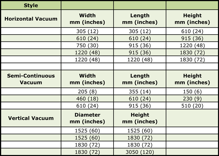
From minuscule medical implants to massive aerospace engine parts, vacuum furnaces process components that come in a variety of shapes and sizes. The challenge that faces a furnace operator is to load parts in such a way as to maximize efficiency (important) but also achieve desired metallurgical properties and minimize distortion (more important).

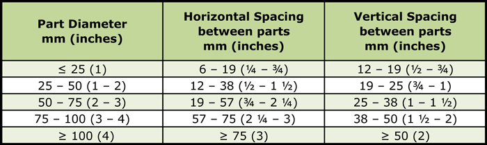
Understanding that loading options generally follow common sense rules can help with the puzzle of load arrangements, spacing parts properly, accommodating geometric irregularities, and loading orientation. This Technical Tuesday feature examines everything to consider about loading parts into a vacuum furnace — from the size and orientation of a workload to the “final spacing . . . [as] dictated by concerns for heating, soaking, flow (of partial pressure or backfill gases), the type and volume of quench media (e.g. oil, gas) and gross load weight.”


Table 1 – Common Furnace Workload Sizes

Table 2 – Typical Part Spacing Requirements


Read more: “Loading of Parts in Vacuum Furnaces”

Photo credit/caption: Vac Aero International / Typical Vertical Furnace Loading Configuration

Common Sense Guidelines for Loading Parts in Vacuum Furnaces Read More »

Hot Zone Insulation Materials Critical in Preventing Heat Loss


Source: Solar Atmospheres of Western PA


With electricity costs increasing, heat treat facilities are looking for ways to harness energy and minimize heat loss through a variety of insulating methods and applications. Heat Treat Today‘s Technical Tuesday feature comes from Reál J. Fradette of Solar Atmospheres Inc of Souderton, PA (with Nicholas R. Cordisco of Solar Manufacturing Inc. contributing), analyzing the different types of furnace hot zone insulation materials with the following points taken into consideration:

A) Hot Zone Designs

  • All-Metal Designs
  • Ceramic Fiber Included Designs
  • Graphite Type Insulated Hot Zones

B) Defining Hot Zone Losses For Different Hot Zone Configurations

  • Calculating Power Losses For A Given Size Furnace
  • Effect Of Hot Zone Losses On Heating Rates and Peak Power

C) Effect on Power Losses With Various Insulation Layers and Thicknesses

  • Projecting Relative Losses Versus Felt Thicknesses

D) Equating Insulation Designs To Actual Power Usage

  • Projecting Cycle Costs For Different Areas Of Operation
  • Impact of Hot Zone Type on Total Cycle Cost

E) Summary And Conclusions

An excerpt:

The heating rate of a load will dictate the total energy required to heat that load at that heating rate. Heating as fast as possible is not often the best solution to the application.


Read more: “Understanding Power Losses In Vacuum Furnaces”

Hot Zone Insulation Materials Critical in Preventing Heat Loss Read More »

Cooling the Vacuum Furnace: 5 Tips for Prevention, Maintenance


Source: TAV: The Vacuum Furnaces Blog


Andrew Alborghetti of TAV Vacuum Furnaces

It’s frustrating enough for furnace operators to encounter downtime due to failure or faulty equipment, but more so when it can be avoided adhering to basic maintenance procedures and adopting habits of diligence and quick thinking.

Andrew Alborghetti of TAV Vacuum Furnaces offers “5 tips for preventing faults caused by the process water in the cooling system [of a vacuum furnace or by] the use of unsuitable equipment.” In addition, he suggests steps to take when an emergency develops.

In a nutshell,

  1. Maintain specific purity standards of the process water.
  2. Prevent dangerous enrichment by maintaining valves.
  3. Keep an eye on your process water temperature.
  4. Avoid damage from external cold temperatures.
  5. Consider investing in a  closed circuit adiabatic water cooling system.

An excerpt:

“For the vacuum furnace to meet the considerable need for water it must have sufficient capacity (tub or tank) to quickly transfer heat from the furnace and from the load. The capacity of the tank determines the size of the system for cooling the water contained in it. Of course, the bigger the tank, the smaller the water cooling system it contains. When there are numerous furnaces, the size of the tank is calculated based on averaged values for behavior in the respective heat cycles.” ~ TAV Vacuum Furnaces

Click below for more on the 5 tips as well as steps you can take should your shop face an emergency such as a power outage that affects the water cooling system


Read more: “The Furnace Cooling System: 5 Tips to Avoid Damage”


Photo credit: TAV Vacuum Furnaces Blog

Cooling the Vacuum Furnace: 5 Tips for Prevention, Maintenance Read More »

Binder Removal in Vacuum Sintering


Source: TAV: The Vacuum Furnaces Blog


Andrea Alborghetti, Technical Manager of TAV Vacuum Furnaces

Heat Treat Today previously posted Parts 1 and 2 of this series on vacuum sintering. Part 1 focused on the two processing steps of debinding and sintering. Part 2 addressed primarily the vacuum sintering furnace itself. This installment analyzes the process and variables involved with binder removal.

Andrea Alborghetti, technical manager of TAV Vacuum Furnaces and contributor to the company’s blog, provides an analysis of burning vs capturing binders, addressing advantages as well as problems that may arise and how to execute control in the process, as in this example:

“One thing that is worth clarifying is that the flames usually seen on the outlet of kilns that use combustible gases (hydrogen, for example) as the process gas, were not originally designed to burn the binder disassociation residues to reduce emissions to the legal limits. Rather, it is solely for disposing of the emitted hydrogen safely, thus avoiding hazardous, potentially explosive atmospheric concentrations being created outside of the kiln.”

Read more for further analysis of binder removal, including discerning the type of residue found with your process: “Perfect Vacuum Sintering Step by Step #3”

Binder Removal in Vacuum Sintering Read More »

Coatings Reduce Surface Temps, Firing Times for Kilns and Furnaces Alike


ThomasNet.com


Today’s best of the web features a video demonstration from the Crafts Center of North Carolina State University (NCUS), which recently released the results of the trial application of high-temperature ceramic coatings to the linings of kilns used at the center.

Cone 10 Gas Reduction Car Kiln at North Carolina State University Crafts Center

Jennifer Siegel Clay, studio manager at NCUS Crafts Center, summarizes the process of lining two kilns with coatings from ITC Coatings, which produces high-temperature ceramic coatings for kilns, forges, furnaces, ovens and metal equipment, first developed in 1980 in Alliance, Ohio, by Feriz Delkic, a ceramic engineer who was running his own pottery business at the time. ITC Coatings provides solutions to problems faced by industries with heat treatment processes such as steel, power generation, and petrochemical, as well as ceramic artists and home hobbyists all over the world.

The first kiln, a 50 cubic foot Cone 10 gas reduction car kiln was coated with ITC 100HT. The outside surface temp was reduced by 30+ dF and the firing time was reduced by 1 hour (28 hour firing). The second kiln, a Barrel Raku kiln, was coated with ITC 296A. The outside surface temperature was reduced by 50+ degrees F, firing time was reduced by half, and gas consumption was reduced by greater than one third. Siegel Clay refers to it as “armor for your kilns.”


Read more: “ITC Technical Ceramic Coatings Announces Data Results from North Carolina State University Product Installation” and “Kiln Application Results: Gas Consumption Reduced by More Than 30%”

Watch the video:

Coatings Reduce Surface Temps, Firing Times for Kilns and Furnaces Alike Read More »

A Heat Treater’s Primer on Getter Materials


Source: VAC AERO International


A common dilemma for operators of vacuum systems is to protect the integrity and maintain the life expectancy of components when the presence of unwanted gaseous contaminates threatens to destroy the sensitive materials in the processing environment. Getter materials are the MVPs that step up to the plate to protect work in a low-pressure vacuum environment.

Table 1 [1] Getter Capacity of Common Materials
The folks at VAC AERO International have provided a primer on getter materials which answers the heat treater’s questions, such as:

  • What is a getter?
  • What are the properties of getter materials?
  • What materials are best as getters for most heat-treating applications? What about for more sophisticated applications?
  • What are non-evaporative getters, and what role do they play?

“For heat treaters, getters are often considered a last resort to help keep parts ‘bright and clean’. In point of fact, they play an important role in successful vacuum processing of many highly sophisticated products and materials. As a result, we need to do a better job of understanding their role; how and where they can help.”


Photo Credit and caption: Titanium Discs used as a Getter Material in Brazing of Oxidation Sensitive Components – (Photograph Courtesy of California Brazing, Newark, CA)

A Heat Treater’s Primer on Getter Materials Read More »

Matching Gases with Vacuum Heat Treatment Operations


Source: VAC AERO International


Relative Gas Supply Cost Notes: [a] Based on a minimum usage of 2830 cubic meters (100,000 cubic feet) per month. [b] All gases compared to nitrogen whose relative cost is unity. [c] Based on liquid supply.
Heat treaters use a variety of gases with vacuum furnaces during the processing cycle in partial pressure operation, for backfilling to atmospheric pressure at the end of the processing cycle, and for cooling/quenching. In this article, VAC AERO describes the most common of these gases — (in order of frequency of use) nitrogen, argon, hydrogen and helium — as well as other common gases such as various hydrocarbons and ammonia (for vacuum carburizing/carbonitriding) and specialty gases such as neon (for certain electronics applications), and analyzes their uses and value in various vacuum heat treating processes. In addition, their relative cost per 100,000 cubic feet, the liquid properties and physical properties of common backfill gases, and the conversion between common pressure and vacuum units are explored.

Read more: “Types of Backfill, Partial Pressure, and Cooling Gases for Vacuum Heat Treatment”


Matching Gases with Vacuum Heat Treatment Operations Read More »

Heat Treat CEO Comments on 3D TUS Tool

Shaymus Hudson - Heat Treat Radio #5Mr. William Jones, CEO of the Solar Atmosphere Group of Companies, listened with interest to the recent Heat Treat Radio podcast featuring Phoenix Heat Treating president, Peter Hushek. Peter introduced a new 3D TUS tool, Virtual Visual Surveys.

Below, Mr. Jones offers his comments about this new tool and TUS practices in general.

If you’d like to listen to the Heat Treat Radio episode that sparked these comments, click here.

Please note that immediately following Mr. Jones’ comments is a response from Peter Hushek.


Unedited comments from Mr. Bill Jones, CEO, Solar Atmospheres & Solar Manufacturing…

Like Peter Hushek we have been in this TUS business for more time than we like to remember. So, most up to date HT companies track our TUS data on paperless video recorders and down load onto an Excel spread sheet and plot out the data a minimum of every 30 seconds. This is done with a preprogrammed digital temperature controller thru the necessary ramps, soaks, and set points. The Excel spread sheets also contains all the survey and controller TC correction factors. Prior to the survey each data point contains the preset temperature controller PID parameters. All survey TC’s are set into their preset locations per AMS 2750E with careful notation to position and correct TC length and care for equal hot / cold lengths. Prior to survey each electronic instrument is checked with a calibrated thermocouple millivolt run-up box and each instrument calibrated. Normally midafternoon each furnace under test is set up thus and the survey to run preprogrammed overnight. Our QC department downloads the data, reviews and makes the pass fail decision, within a few hours, the next day. If the TUS failed back to maintenance to look into the issues, make corrections and rerun the TUS. Problems are not always furnace related but thermocouple, TC position, jack panel, jack panel wiring, instrumentation, and numerous other issues. I view the VVS 3D presentation as an aide but only part of the story”.

William R. Jones, CEO, FASM
Solar Atmospheres Inc.
Souderton, Pa.

More about Solar Atmospheres? www.solaratm.com


And Peter Hushek’s unedited response to Mr. Jones’ comments…

In regards to the response from the listener I can say he makes some valid points.  There are many issues that can affect the outcome of a TUS.  We realize that the evaluation of the furnace uniformity involves many aspects and we are only addressing the data generated by the process.  We believe that when companies begin the process of actual data analytics they will become more aware of the process and improve the quality of their processing as a result.  VVS is only beginning to scratch the surface of the data flow that occurs daily in processing companies.  We look to greater innovation through customer supplier interface as well and technological improvements that can be used as feed stock to improve future generations of this software.  We are only starting the process and I hope the market realizes that this is not a static process or company.


If you haven’t done so already, clicking here to listen to the Heat Treat Radio episode being discussed above.

To find out more about VVS, go to www.virtualvisualsurveys.com.

Peter Hushek. Heat Treat Radio podcast - President of Phoenix Heat Treating

Heat Treat CEO Comments on 3D TUS Tool Read More »