THERMOCOUPLES TECHNICAL CONTENT

Heat Treat Radio #61: Thermocouples 101 with Ed Valykeo, Pelican Wire (Part 1 of 3)

Heat Treat Today publisher Doug Glenn sits down with Ed Valykeo from Pelican Wire in the first of a three-part series on all-things thermocouples. This first episode covers the history, types, vocabulary, and other basics of understanding how thermocouples work.

Below, you can either listen to the podcast by clicking on the audio play button, or you can read an edited transcript.


The following transcript has been edited for your reading enjoyment.

Doug Glenn (DG):  Ed, why don't you take a minute, as we typically do on these interviews, to talk briefly about you and your background especially your qualifications for talking about thermocouples.

CLICK the image to access the article!

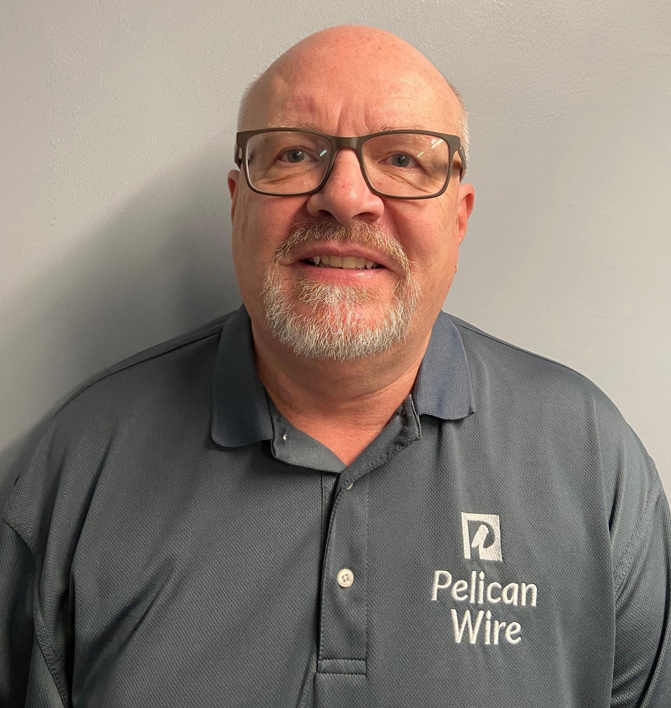
Ed Valykeo (EV):  I've actually been in the wire and cable industry for a little over 40 years now.  I actually first started in the industry as, well maybe not a grunt, but certainly I was called a “melter's helper.”  I worked at a company called Hoskins Manufacturing in Ann Arbor, Michigan where we actually melted the raw materials to make thermocouple wire, resistance wire, and a whole host of other things.  I was actually the guy that, after we got done pouring that molten metal into the molds to make the ingots, was cleaning up all the mess that happens after you pour and you're pulling those ingots.

That's really where my career started, with Hoskins.  As a matter of fact, it kind of ran in the family.  My dad retired at Hoskins with 42 years of service with Hoskins, so it was kind of a natural progression that, eventually after I got out of the service, I ended up joining Hoskins.  I was there about 18 years at Hoskins Manufacturing, again, starting out right at the bottom.  I worked my way up to becoming an associate engineer working in the R&D department.  That's where my career really started focusing a little more on thermocouples.  I enjoyed working with thermocouples.  We were developing some new products using thermocouple wire and things like that.

Ever since then, I've kind of stayed in thermocouple arena at some of the other places I've worked.  After I left Hoskins, I started working for companies that insulated wire.  So, we were taking the wire, like we made at Hoskins, and we were putting a whole host of insulations on it from ceramic braid to extruded products and things like that.  And, again, both the companies, and even the one I'm currently employed with at Pelican, but before that I was working for a company out in New Hampshire called PMC, are real similar, it's just we insulated wire.  So, we purchased the raw materials (raw wire from Hoskins or whoever) and then insulated it.

DG:  For the unbaptized in this topic, what are thermocouples, how do they work, how do they come about, and then are the modern-day thermocouples any different than the thermocouples of old?

EV:  I always start out with a little bit of history about thermocouples, whenever I'm talking about them, just to give people background.  Thermocouples were introduced in the early 1800's with the most significant developments taking place in Europe.

One of the very first gentleman that worked on it was Alessandro Volta.  You can probably recognize the name because Volta actually is the volt, today, which everybody recognizes, not just with thermocouples but, obviously, in the electrical industry too.  He basically built a couple thermopiles using metals, silver and zinc and some cloth in between them, soaking them in salt water, and discovered that it would produce a voltage.  That's kind of how it got started.  The significance of that discovery was that there is a source of steady and reliable current flow from using dissimilar metals and saltwater and things like that.

Thomas Johann Seebeck, Baltic German physicist, who, in 1822, found the relationship between heat and magnetism.

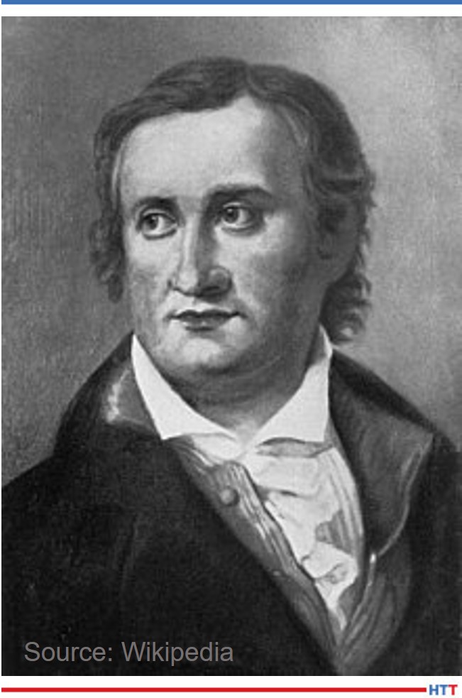
Over the years, many others have experimented with the phenomenon.  Probably the most famous, anybody that's in the thermocouple industry will hear it a lot, in 1821, Thomas [Johann] Seebeck announced that he had discovered that when two dissimilar metals were placed in a closed loop and one of those junctions was exposed to a change in temperature, electrical current was produced.  This production of the electromotive force and electromatic force is the electric current is known as "the Seebeck effect" or "Seebeck coefficient."  It was, obviously, much later, before everything was understood and correct mathematics, but Seebeck's name will always and forever be associated with the discovery of thermoelectricity and thermocouples.  Again, even to this day, even ASTM books reference Seebeck coefficient.

Some other gentlemen that we involved, again you'll recognize some of these, were Michael Faraday, Georg Ohm, Claude Pouillet, and Antoine [César] Becquerel.  It was Becquerel, actually, that suggested using Seebeck's discovery for measuring high temperatures.  He proposed the strength of the current generated was proportional to the change in temperature in exactly the principle behind the thermocouple.  We're measuring temperature, whether it's 200 degrees or 2300 degrees.  That's how the modern day thermocouple got started way back in the early 1800's.

DG:  And the modern-day thermocouples are, essentially, the same as that?  Have there been any major changes?

EV:  In reality, Type J was the first thermocouple to really be experimented with.  After Type J, then some additional thermocouple types came on board.  People experimented with other metallurgical compositions to develop different millable outputs.

DG:  Let me understand:  Type J, what that basically the first type of thermocouple that was developed?

EV:  Let me back up a little bit.  Actually, the early metal thermocouples were based on what we can call noble metals.  Noble metals are rare earth elements such as platinum, rhodium, tungsten and uranium.  The problem with the noble metals is that noble metals are much more expensive than our base metal thermocouples, or what we call base metal thermocouples, today.  Base metal thermocouples, today, typically the compositions are just a handful of elements.  You have iron, nickel, chromium, copper and things like that, which is considerably cheaper than the noble metals, the platinum and rhodium and things like that.

DG:  I want to learn this history a little bit, because it's just kind of fascinating to me.  So, the very first ones were made of noble metals, primarily. So, they would put those together and then, basically, we said, "This is great but it's way too expensive.  Can we get the same effect, if you will, (the difference in voltage, or whatever, between dissimilar metals), if we use a little less expensive metals?"

EV:  Right.

DG:  You’ve said there is a difference voltage when there's a difference in temperature.

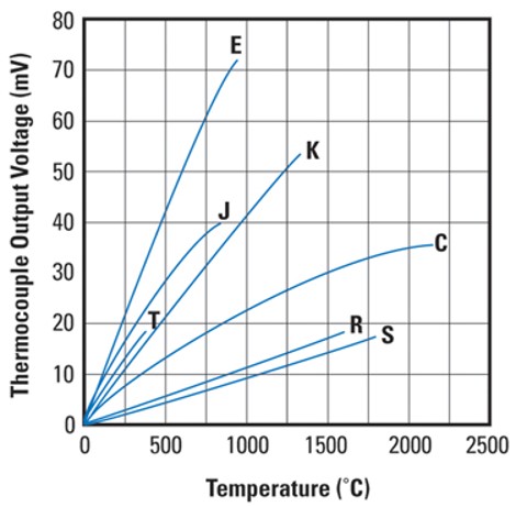
EV:  The EMF (electromotive force) generated by the thermocouple is linear.  So, at 200 degrees, it produces this amount of voltage, at 300 degrees, it produces this much.  All the thermocouples are, basically, the same principle.  It's very linear.  That's one thing that is good about a thermocouple- the EMF output is linear.  You aren't producing a millivoltage at 200 degrees and then at 300 it goes down and then at 500 it goes back up; it's linear proportional to the temperature.

CLICK the image to access the article!

DG:  I have heard in the past, and you mentioned it here, maybe we can discuss it a little bit:  noble metal versus base metal.  Obviously, we know noble metals, you mentioned what those are.  Those are expensive; they work to do the same thing.  Base metals, though, tend to be what?  Which metals?

EV:  As I already mentioned, the nickel, chromium, copper, and others.

DG:  And those are, in fact, just less expensive, right?  Essentially, they do the same thing but they're less expensive.

EV:  Exactly.  But, there are some other differences, too, between the noble metals and the base metal thermocouples.  When you're talking noble metals, the platinum and the rhodium, and things like that, they can handle much higher temperatures than even the base metal thermocouples.

DG:  I'm going to make an assumption, but probably the vast majority of the thermocouples used in the heat treat industry are probably base metal, although, I'm sure they've got some specialized ones for high temperature, which probably jump into noble metals.

EV:  Absolutely.  A lot of the base metal thermocouples are used in the load sensors where they're putting multiple sensors in and then the oven may be controlled by a noble metal.

DG:  The different types of thermocouples.  You mentioned, and I've forgotten the letter already, that there are different types.  Was it Type J you mentioned?

EV:  Yes, Type J.

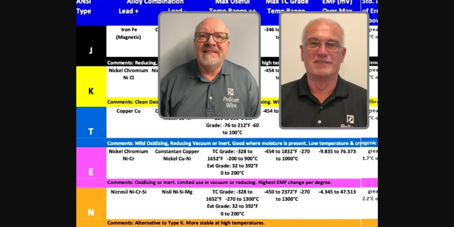
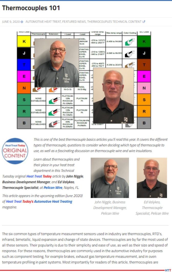
DG:  OK.  We've done a study recently asking about what's the most popular one in the heat treat industry, but I know we listed down there J, E, K, N, and T.  Can you run us through those and tell us what are the differences, and whatnot?

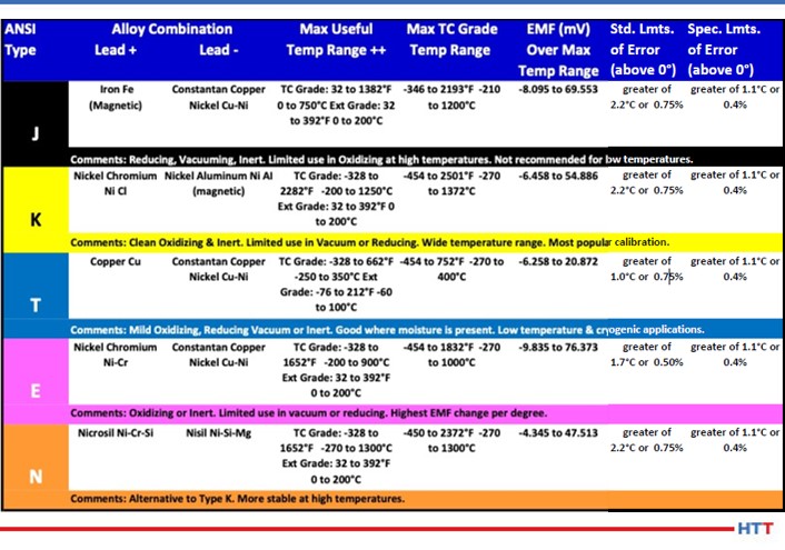
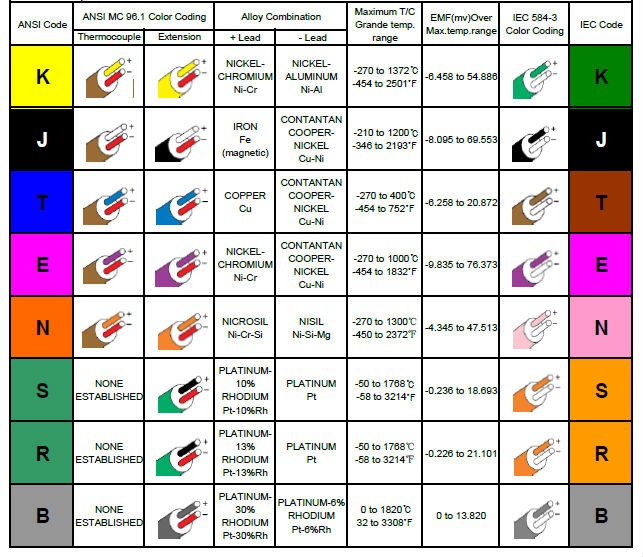
EV:  J, E, K, N and T are the most common noble metal thermocouples.  Obviously, you've got two dissimilar metals or, what we refer to in thermocouples, two legs of the thermocouple – the positive leg and the negative leg.  So, for instance, on a Type J thermocouple, you're using iron as a positive leg, which is basically pure iron, (there are some coatings on the iron to help against oxidation and things like that), and the other leg is a copper nickel alloy.  That makes up the two legs of the Type J thermocouple.

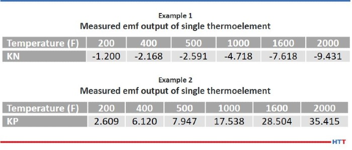
If we look at Type K thermocouple, the negative leg is the KN which is, basically, just high nickel with a little bit of chromium; the KP leg, or the positive, of Type K is higher content nickel chromium.  There are also some other minor elements.

With Type T, the positive leg is pure copper.  The TN leg is, again, a copper nickel alloy.  So, when we talk about Type E, what is interesting is that with the Type E thermocouple, you're actually taking the Type KP leg and matching it with the TN leg.  So, again, it's just a mismatch or some hodgepodge of some legs.

DG:  So, you're using some lingo that I'm just picking up on and I want to make sure our listener's are, as well.  You talk about a P and an N leg.  Obviously, you didn't say it, but you're talking about a positive leg and a negative leg.

EV:  Yes, I'm sorry.  KP and KN.  So it's K positive and K negative leg.

DG:  Great.  So, with the Type E, you're taking a few and switching them around and matching them up and seeing what you can come up with.

EV:  Yes, that's the E, and I already mentioned the T.  N is a relatively newcomer to the thermocouple industry.  I say new, but it's still probably 40 or 50 years, I'm not sure when it was developed.  But, again, the Type N is similar to the Type K where the KP leg is a nickel and the KN leg is nickel and some silicon.  So, it's just a little bit different composition from the Type K thermocouple.  But, there are some differences.

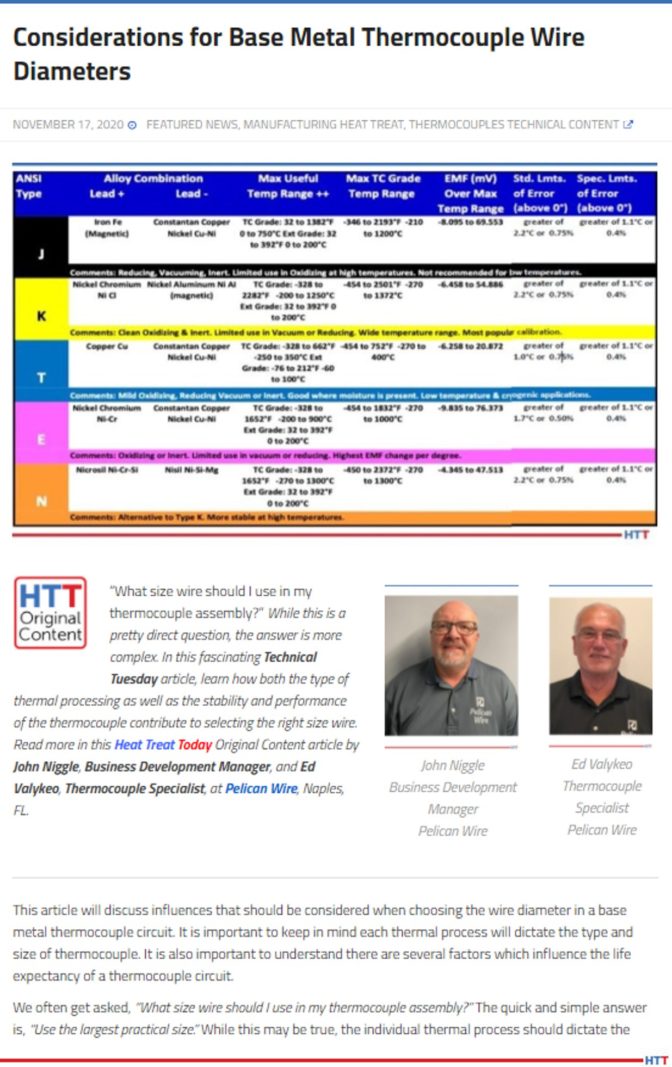
Some of the differences, when you're looking at the different types of thermocouples, for example, Type E has the highest EMF output of any of the thermocouples.  Your question might be, "Well, why wouldn't we just use Type E because it has the highest output?"  What the higher EMF output means is that the sensitivity is a little bit greater in the Type E thermocouple.  Then why wouldn't we use that throughout all the industries?  Well, the short answer is, a couple things:  Type E has a limited temperature range, because, again, you're using that TN leg which is copper nickel alloy and the melting point of a copper nickel alloy is much lower than a nickel chromium alloy.  So, that's some of the differences, and with all the thermocouple types, also.

Each one has their own EMF output at certain temperatures but one of the biggest considerations is, really, the environment that you're using the thermocouples in.  Type K has good oxidation resistance; Type J, not so much, because you've got a pure iron leg which is going to oxidize much faster.  That's some of the differences between the individual thermocouple types.

DG:  I assume that if there's oxidation, or any type of corrosion or anything of that sort, it's going to change the EMF, it's going to change the reading and therefore that thermocouple, out the door she goes.

EV:  Absolutely.  And there have been even some recent changes in some of the specifications that some of the heat treaters are using nowadays where they finally realize that these thermocouples do deteriorate over time and so they start limiting the amount of uses that each thermocouple can be used in, in a bunch of different applications, but heat treating mainly.

DG:  Let's pause for just a second and do a little vocabulary.  You've mentioned EMF a couple of different times.  Could we have just a brief review of that just to make sure?  Also, I've heard about millivolts.  Are those two things related?  If so, how?

EV:  EMF stands for electromotive force.  It is, basically, when two dissimilar metals are put in contact with each other, a small voltage is generated.  When we're talking about millivolts, that's exactly what we're looking at: a millivolt is 1/1000 of a volt.  It's a very small amount.  If you look at some of the millivolt outputs for some of these thermocouples, at 200 degrees, for example, you're putting out .560 of a millivolt.  So, these are small.

DG:  And you're saying that it was the Type E that has the highest millivolt of all, so the current that is produced between those dissimilar metals is the highest, but you can't always use that one because in certain temperature ranges you're going to melt one of the legs.

EV:  Exactly.

DG:  The millivolts are measured by what?  I mean, it goes into an instrument that is able to read that?  What is that instrument?

EV:  Actually, some DVMs (digital volt meters) have the capacity to measure in the millivolt range.  So, it could be as simple as a digital voltmeter.  But, in the industry, we have temperature controllers, things like that, that you hook a thermocouple up to and it measures the EMF and then it converts it into a temperature.

DG:  It will measure that millivolt and then tell us what the temperature is?

EV:  Right.  With the instrumentation nowadays, it has the formulas in its memory, or whatever, and can convert that millivolt into an actual temperature that you actually read on a meter.

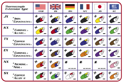
DG:  We've got an EMF which is measured in a millivolt.  It's going to travel across a long wire, I assume, to some place where it's going to be read.  Let's talk about that wire a little bit.  The impact of this, whatever EMF is being created, millivolt, what about that wire?  Tell me about it and what do we need to be careful of, etc?

EV:  We're actually saving that for another podcast, but I will touch on it a little bit.  So, there are limitations on the length of the thermocouple.  There are a lot of different mindsets, but probably the one I've heard the most is no longer than 100 feet.  So, you have your thermocouple sensor and that arrangement, the configuration, can be a number of ways.  At PMC Corp. we insulate the wire.  You could just take that insulation off at the end, weld the junction there, stick it and [. . .] then run it to a meter.

But in other industries, you may have it in a ceramic tube because of the temperature it's being used at.  You have a ceramic tube with a connector at the end, you may run what we consider an extension wire from that point all the way back to your instrumentation.  Again, the general rule of thumb, is 100 feet.

DG:  Let's talk about that wire with the different types of thermocouples.  What do we need to be sensitive to?  What do we need to be careful about?

EV:  Again, temperature range is probably the first consideration, but then also the environment that it's in.  Again, each thermocouple has its limitations on the environment.  Some are good in a vacuum, other thermocouples are not good in a vacuum.  Some thermocouples are good just in air, (like Type K), but Type J is not so good.  It still can be used in air but it will oxidize faster.

Like I said, in an environment of a vacuum, some thermocouple elements will actually leech out or evaporate out and that definitely would cause a problem with the EMF output and would have an erroneous reading.  Certain acids you can use some thermocouples in, others you can't.

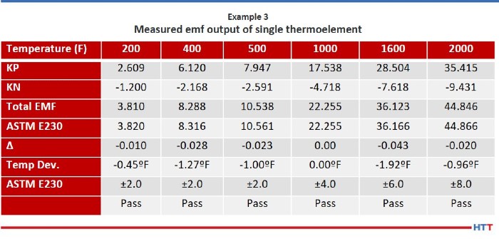
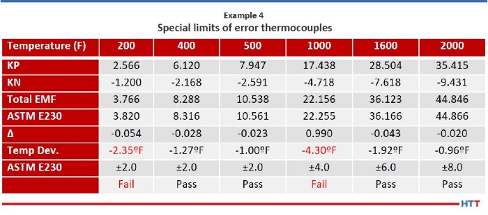
DG:  With all of this pyrometry stuff going around, especially the AMS2750 revision, there are a lot of places where the tightness of the tolerance on the temperature really needs to be paid attention to.  Are some thermocouples inherently tighter tolerance, where they can go down to + or –2, or less than that?

[blockquote author="Ed Valykeo, Pelican Wire" style="2"]Special limits of error is the tightest tolerance, and that's according to ASTM.  But, there are some customers and some companies that want tighter tolerance material.  So, when we talk about that, that's really a special order.  Now you have to back all the way back up to the melters that melt these elements and make the thermocouple wire.  It's on them to produce something that is a tighter tolerance. [/blockquote]

EV:  Again, that was something we were going to touch on a little bit later, maybe on another podcast, because it can be a whole category on its own.

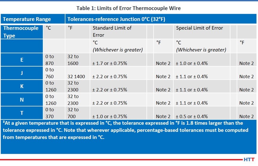
But, yes.  If you think about in general, overall, when we're thinking about the different thermocouple types, they basically all have the same tolerances according to ASTM.  The rule of thumb, that we kind of use, is from say 200 degrees to 500 degrees, the tolerance on all thermocouples are + or - 2 degrees if you want special limits of air material.

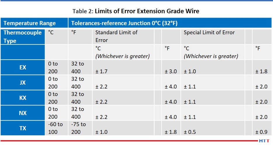
Now, there are other tolerances.  In the thermocouple industry, you’ll here – at least calibration-wise – you'll hear special limits of error, standard limits of error and extension grade.  Special limits of error is the tightest tolerance, and that's according to ASTM.  But, there are some customers and some companies that want tighter tolerance material.  So, when we talk about that, that's really a special order.  Now you have to back all the way back up to the melters that melt these elements and make the thermocouple wire.  It's on them to produce something that is a tighter tolerance.  Once that metal is poured in that mold and it's processed down the wire, it is what it is.  When they calibrate that wire, you can't really do a lot with it to change the EMF output, per se, other than there are some heat treat operations that can, what they call, stabilize, and there are processes to oxidize thermocouple wire, and things like that, but you're pretty much stuck with EMF right from the melt.

DG:  And it's dependent on the material composition or quality of the material.

EV:  Absolutely.  In some cases, they may melt 10 melts to get 2 special limit of air thermocouple types.  I don't think it's quite that bad, bur from my early melting days, we've had to downgrade many a melt because it didn't quite meet the tolerances.

DG:  Just reviewing, we talked about the basic history, how they got started.  We talked about the difference between noble versus base metal thermocouples.  We talked about the different types.  We defined EMF, electromotive force.  We talked about millivolt a little bit.  We talked about the wire, the differences in what we need to pay attention to as far as wire, and some other considerations like temperature range, calibration tolerance and environment.

EV:  Just so you know, the only base metal thermocouples there are, at least what ASTM recognizes, are the Type J, E, K, T and N.  We covered all the base metal thermocouples.

DG:  Just out of curiosity, a noble metal thermocouple, what are those?

EV:  There is a fairly large list of those.  You've probably heard of thermocouple Type R or Type S thermocouple.  Those are all made with noble metal thermocouples.  It's not really considered a base metal, but tungsten uranium thermocouples.  Those are in more the noble metal category Type C.  There is even development of some other additional noble metals:  gold is used.  Thermocouples are made out of gold.

DG:  Those could be expensive.  Of course, some of those other metals are more expensive than gold, so, who knows?

Well, that's very interesting.  So, J, E, K, N and T are all base metal thermocouples.

I want to make sure that we give appropriate credit to your company.  We talked about the fact that you're from Pelican Wire, part of the wire expert group.  I want to make sure that our listeners know that they can go check out your website which is pelicanwire.com.  You're not obligated to do so, but would you like to give out any other information where they can get a hold of you?

EV:  Yes.  Through the Pelican website, you can certainly get a hold of me.  Our number is on the website.  It's 239-597-8555 and it goes through a central board.  If anyone wants me, they can just ask for me through the operator.

Doug Glenn <br> Publisher <br> Heat Treat Today

Doug Glenn
Publisher
Heat Treat Today


To find other Heat Treat Radio episodes, go to www.heattreattoday.com/radio and look in the list of Heat Treat Radio episodes listed.


Heat Treat Radio #61: Thermocouples 101 with Ed Valykeo, Pelican Wire (Part 1 of 3) Read More »

Measuring Furnace Temperatures in Oxidizing Atmospheres

Source: AZO Materials

Measuring temperatures inside a furnace can present a number of challenges: temperature cycling, high temperatures and hostile atmospheres exceeding the limits of several measurement devices while others have significantly reduced lifetimes and poor accuracy. This article discusses some of the challenges associated with temperature measurement in furnaces where oxidizing and reducing atmospheres are employed in microelectronics fabrication.

An excerpt:

"The Type K is low-priced and can be used across a temperature range from -200 to 1250 °C (-328 to 2282 °F). However, metallurgical changes at temperatures more than 1000 °C (1832 °F) decrease accuracy, and cycling via this temperature induces hysteresis effects, further reducing accuracy. Type K thermocouples are also vulnerable to corrosion in an oxidizing atmosphere."

Read more at "Measuring Furnace Temperatures in Oxidizing Atmospheres"

best of the web

Measuring Furnace Temperatures in Oxidizing Atmospheres Read More »

AMS2750F – Changes and Implementation

OCAMS2750F? What are the new changes? How do you implement them? This informative article from Heat Treat Today's Aerospace 2021 issue will help you navigate through the uncertainty of these changes to ensure successful compliance.

This Technical Tuesday is an original content contribution from Jason Schulze, the director of technical services at Conrad Kacsik Instrument Systems, Inc. Check out other technical articles here.


Jason Schulze
Director of Technical
Services
Conrad Kacsik Instrument
Systems, Inc.

Introduction

AMS2750F has been released for approximately 7 months now. This specification applies to manufacturers and suppliers who heat treat aerospace material. AMS2750F is typically communicated via industry standards such as SAE/AMS specifications as well as customer purchase orders and part prints. This specification gets even more complex when you apply Nadcap heat treat accreditation to the equation as Nadcap has a checklist dedicated to AMS2750, which, as of January 2021, has yet to be released.

In this article we will examine some of the changes within AMS2750F as well as discuss the implementation process for suppliers.

AMS2750F Changes

General Changes

AMS2750F now has 25 tables, where there were previously 11. These tables are no longer at the end of the specification (like most SAE/AMS specifications); they are now placed throughout the specification adjacent to paragraphs to which the rewrite team thought they applied. The challenge with this is that all aspects of AMS2750 are interconnected. For example, one change in the qualified operating range of a furnace will directly affect other areas, such as instrument calibration and the temperature at which an SAT is performed.

Previously, temperature values were expressed in whole numbers. They are now expressed to the tenth of a degree (X.X°F). With this change, I would recommend suppliers follow suit in their own pyrometry procedures and associated documents: think of it as comparing apples to apples.

Scope and Definitions

The definitions section is important, especially to those who are new to AMS2750F who may be working to interpret some of the verbiage within the specification. The specification has increased the number of definitions from 79 to 87. A good example of these definition changes is the comparison of expendable thermocouples versus nonexpendable thermocouples.

  • EXPENDABLE SENSOR: Sensors where any portion of the thermal elements are exposed to the thermal process equipment environment.
  • NONEXPENDABLE SENSOR: Sensors having no portion of the thermal elements exposed to the thermal process equipment environment.

This example is especially important because it is such a major change from the previous revision of AMS2750. The definitions section within AMS2750F should be utilized often by suppliers to ensure comprehension and conformance.

Thermocouples

As simple as thermocouple technology is, there are many requirements within AMS2750F governing thermocouple usage, error, replacement, etc. Previously, AMS2750 did not address resistance temperature devices (RTDs). It now requires RTDs be nonexpendable, noble metal, and ASTM E1137 or IEC60751 (Grade A).

I do not see this next change as anything major, because what I’m witnessing in my consulting all around the US and Mexico are that suppliers already conform. Thermocouple hot junctions (the tips of the thermocouple measuring temperature) are made by either twisting, welding, or a combination of both.

In my experience, it is rare to see a thermocouple supplier/manufacturer issue a thermocouple certification that is nonconforming. Whenever there are issues with thermocouples, it is typically because the supplier did not communicate the correct information. With that, thermocouple error should be considered and communicated correctly.

Thermocouple permitted error has changed to the following:

  • Type R & S: ±1.0°F or ±0.1%
  • Type B: ±1.0°F or ±0.25%
  • Base metal: ±2.0°F or ±0.4%
    • AMS2750E permitted ±4.0°F or 0.75% for TUS, load and furnace thermocouples.

Exceptions:

  • Note 11: For temperatures <32°F or <0°C for Types E and T only, calibration accuracy shall meet the following:
    • Type E: -328 to 32°F, ±3.0°F or ±1.0 % for either, whichever is greater
    • Type T: -328 to 32°F, ±1.8°F or ±1.5 % for either, whichever is greater
  • Note 13: When correction factors are used, type B load sensors shall meet calibration accuracy of ±2.7°F or ±0.5% and types R and S load sensors shall meet calibration accuracy of ±2.7°F or ±0.25%

AMS2750 has always required that the results of an SAT and TUS must reflect corrected temperatures. This would mean when expressing the final ± readings of a TUS, those readings must be identified as corrected values. The challenge may come when you need a correction factor from a thermocouple certification where there is not a temperature value for the test. AMS2750F now addresses this situation:

  • PARA 3.1.4.8 - Interpolation of correction factors between two known calibration points is permitted using the linear method.
  • PARA 3.1.4.9 - Alternatively, the correction factor of the nearest calibration point shall be used.
  • PARA 3.1.4.10 - Whichever method is used shall be defined and applied consistently.

Each supplier must decide what method they will utilize and document this. Know your customer requirements; some customers may not permit certain methods.

Sensor usage has changed dramatically, especially for expendable test sensors. These thermocouples are now limited to a single use above 1200°F regardless of the type. Between 500°F and 1200°F, Type K may be used five times or three months, whichever occurs first and for Type N, 10 times or three months, whichever comes first. Below 500°F, Type K may be used for three months with no limit to the number of uses, and Type N may be used for six months, with no limit to the number of uses. I can understand how this may seem like a lot to understand and filter through, but I can assure you, we will get used to it as we did with AMS2750E.

Thermocouple certification requirements have also changed. I do not foresee any issue with this as what is listed is, for the most part, already on existing thermocouple certifications. I would advise suppliers to check the requirement in bullet point “E.” (Figure 1)

Figure 1

Instrumentation

There were several major changes within the instrumentation section. The first one is readability of furnace recording and field test instruments. Previously, readability for all furnace and field test instruments was 1.0°F; it is now 0.1°F, or to the tenth of a degree. Suppliers may find this challenging to meet as not all field test instruments on the market are capable of this. An easy way to test yours is to either source or read the value on your field test instrument at 999°F. Then, increase the temperature to 1000°F.

On some units, when a temperature is reading/sourced below 1000°F, it will show to the tenth of a degree, but when increased above a tenth of a degree, the value in the tenths place will be removed and only whole numbers will be shown. If this is the case, you will need to purchase a new field test instrument which displays values to the tenth of a degree regardless of whether values go above 1000°F.

The second major change is timers or digital clocks on recording devices. This change makes sense, as most thermal cycles used to achieve metallurgical transformation are time-dependent and have specific tolerances that apply. AMS2750F now requires that these timing devices must be accurate to within ±1 minute per hour. There is a caveat which states that as an alternative, suppliers may have a synchronized system linked to NIST via internet system which is verified monthly and will support the ±1 minute per hour requirement. With that, a new paragraph, regarding stopwatch calibration and accuracy requirements, has been inserted adjacent to the recording device timing calibration requirements.

The third change, simple and straight forward, is that the instrument number or furnace number must be stated on the calibration sticker.

Additionally, changes have been made to what is required on an instrument calibration report. (Figure 2)

Figure 2

System Accuracy Testing (SAT)

There are several changes within the SAT section that should get attention. One which may continue to be overlooked is whenever an SAT cannot be performed (not that one fails), but if no product was run and the furnace was locked out, the SAT could be performed with the first production run (AMS2750E, para 3.4.2.4). This is no longer an option. AMS2750F now states that, in this situation, the SAT must be performed prior to putting the furnace back into service (or prior to production).

Furnaces that have multiple qualified operating ranges (i.e., CL2 from 1000°F to 1600°F and CL5 from 1601°F to 2000°F) must have the SAT performed in each range, at least annually. This means that if you typically run production at 1550°F and SATs are run at the same time, at least annually, an SAT must be processed above 1600°F to catch the CL5 range.

The alternate SAT process was the source of much confusion when revision E was released. Previously, single use thermocouples (i.e., load thermocouples) did not require an SAT per AMS2750D, para 3.4.1.2. When AMS2750E introduced the alternate SAT, the wording was so poor it caused suppliers to misunderstand the requirement, and subsequent audits yielded quite a few related findings. I have written previous articles explaining the alternate SAT process in detail, so I will not be going into this topic too deeply. For information, please visit www.heattreattoday.com and search Jason Schulze.

The changes within the alternate SAT section primarily amount to clarification and incorporation of what was previously in Nadcap’s pyrometry reference guide. That being said, there really isn’t much to speak of in this section for existing Nadcap suppliers, but one item to point out is how the wording has changed. Previously, it applied to single use sensors or sensors which were replaced more frequently than the SAT frequency requirement. This has been changed to state that the alternate SAT applies to load sensors used only once. Nadcap heat treat auditor advisory HT-20-010 has clarified this further. If load sensors are used more than once, the alternate SAT does not apply, and the comparison SAT must be used.

There were some minor changes to what is required on the comparison SAT report. (Figure 3)

Figure 3

Documentation related to the alternate SAT as well as the SAT waiver have been introduced. These should be examined closely by those suppliers to whom it may apply.

Temperature Uniformity Surveys (TUS)

Among many of the changes in this section, there is one that is not stated outright but is based on verbiage changes within Tables 18 and 19 of revision F regarding frequency. In AMS2750E, Tables 8 and 9, the statement reads “Initial TUS Interval” and “Extended Periodic TUS Interval.” Due to the wording, it was assumed that if four passing consecutive TUSs were needed before going to a reduced frequency, the initial TUS would count as part of the four needed. The modified wording in Tables 18 and 19 of AMS2750F now reads “Normal Periodic Test Interval” and “Extended Periodic Test Interval.” With this change in verbiage, the initial TUS does not count toward the needed consecutive tests to reduce TUS frequencies.

If a supplier uses vacuum furnaces for thermal processes and both partial pressure and low vacuum is used, a TUS must be performed annually in the partial pressure range using the gas applied during production. This is a rather simple change, although it is important to recognize that partial pressure gases, depending on certain variables, can affect the uniformity in the area in which the gas enters the furnace.

Thermocouple location for work zone volumes less than three cubic feet has changed. AMS2750E/Nadcap previously required that the five TUS thermocouples be placed on a single plane. AMS2750F has revised this to require each test thermocouple be placed diagonally opposite of each other. Using Figure 4, this could mean suppliers may choose locations 1, 4, 5, 7, and 8 or 2, 3, 5, 6, and 9.

Suppliers familiar with GE’s P10TF3 specification will recognize this next change as it was a GE requirement long before SAE/AMS introduced it into AMS2750F. Previously, data collection during TUSs needed to start prior to the first furnace or test thermocouple reaches the lower end of the tolerance (AMS2750E, para 3.5.13.3.1). This has changed and now requires data collection to begin when the furnace and TUS thermocouples are no fewer than 100°F below the survey temperature.

The documentation or TUS certification requirements have also changed. Considering that there are so many changes within this section, I will merely point out the letter annotations that apply to changes within Para 3.5.16.1: B, D, F, G, H, J, L, O, R, S, and Y. Some of these items contain simple verbiage changes, although most of them are solid changes and should be incorporated into suppliers’ procedures and forms.

Figure 4

Rounding Requirements

Previously, AMS2750E permitted rounding in accordance with ASTM E29. To the delight of many users, I am sure, this has changed. AMS2750F now permits rounding in accordance with the following options:

  • All rounding must be applied in accordance with a documented procedure and used in a consistent manner.
  • Rounding to the number of significant digits imposed by the requirement is permitted in accordance with ASTM E29 using the absolute method or other equivalent international standards. (Previously, the only method permitted was the rounding method.)
  • The rounding method built into commercial spreadsheet programs is also acceptable.
  • All specified limits in this specification are absolute and out of tolerance test data cannot be rounded into tolerance.
  • Rounding must only be applied to the final calibration or test result.

Quality Provisions

The only change in this section is in regard to pyrometry service providers. The requirement now states, “Beginning 2 years after the release of this specification, third-party pyrometry service provider companies shall have a quality system accredited to ISO/IEC 17025 from an ILAC (International Laboratory Accreditation Cooperation) recognized regional cooperation body. The scope of accreditation shall include the laboratory standards and/or field service as applicable.” It is important to keep in mind that, when verifying conformance to this, the supplier’s scope of accreditation should include reference to AMS2750 with regards to instrument calibration, SAT, or TUS or all three if that is what is performed at your facility by an outside service provider.

Implementation of AMS2750F

he implementation of AMS2750F with suppliers’ systems should be two-fold: not only what is implemented but when it is implemented. Right now, AC7102/8 Rev A, as it applies to AMS2750F, is in the review stage. Its projected release date is April 2021. Regardless, once the new revision of AC7102/8 is released, suppliers will have 90 days to implement AMS2750F.

Implementing AMS2750F must be done in its entirety, not partially. This means internal procedures, forms, purchase orders, etc. should be revised in the background in conjunction with training. Once your team is familiar with the new changes, then all the revised documents should be released at one time. This ensures the whole of AMS2750F is implemented at once and not in stages.

Nadcap heat treat auditor advisory HT-20-007 requires that all thermocouples issued on or after Jan. 1, 2021 must be certified in accordance with AMS2750F. By this time, suppliers should have already revised purchase orders to require this and may have thermocouple certifications reflecting AMS2750F.

About the Author: Jason Schulze is the director of technical services at Conrad Kacsik Instrument Systems, Inc. As a metallurgical engineer with over 20 years in aerospace, he assists potential and existing Nadcap suppliers in conformance as well as metallurgical consulting. He is contracted by eQualearn to teach multiple PRI courses, including pyrometry, RCCA, and Checklists Review for heat treat.

(source: Joshua Coleman at Unsplash.com)


All other images provided by Heat Treat Today


AMS2750F – Changes and Implementation Read More »

Thermocouples: Know Your Limits

OCAre you a heat treater who makes thermocouples? How do you stay within limits? What do you need to know when using specific thermocouple materials? Read all about it in this Heat Treat Today Original Content article by Ed Valykeothermocouple specialist at Pelican Wire, Naples, FL.


Ed Valykeo
Thermocouple Specialist
Pelican Wire

We are often asked, what is the difference between special limits of error, standard limits of error, and extension grade thermocouple wire? Today’s discussion will review base metal thermocouple tolerances for special, standard, and extension grade wire. First, we will look at the difference between a thermocouple wire producer and the different types of thermocouple wire users. Then, we will look at emf (electromotive force) data for single leg thermoelements and how to determine temperature deviation. Finally, we will touch on how thermocouple wire is manufactured at the wire producer.

Thermocouples

Since thermocouple materials are supplied with different levels of accuracy depending on the standard being used, ANSI/ASTM E230 identifies accuracy requirements for standard limits of error, special limits of error, and extension grade.

The two tables below list the accuracy requirements for standard, special, and extension grade thermocouples and thermocouple wire.

A thermocouple is a sensor for measuring temperature in which a pair of wires of dissimilar metals are joined at one end. The other end is connected to an instrument that measures the difference in potential created at the junction of the two metals.

From this definition, we know that a thermocouple must have two wires of dissimilar metals. For example, the positive leg (KP) of a Type K thermocouple consists of nickel and chromium, the negative leg (KN) is nickel, aluminum, and silicon. Type J consists of iron in the positive leg (JP) and copper nickel in the negative leg (JN). It has taken decades for thermocouple wire producers to perfect the chemical composition of each thermoelement to achieve desired emf outputs. When these elements are melted, the electromotive force generated can be predicted.

A thermocouple wire producer is where a thermocouple gets its start. Raw chemical elements such as nickel, copper, chromium, manganese, and silicon are melted to form individual thermoelements. The process of melting metals into a usable wire size is done in several ways. A typical method is to melt and pour to form ingots; ingots are then broken down into bar form, and then the bars are hot rolled into rod before the rod is cold drawn to the desired wire size. Producers supply thermocouple materials in rod, wire, and strip form. There are only a few thermocouple wire producers left in the world today.

Measuring Electromotive Force (emf)

As mentioned above the first step in the life of a thermocouple is the melting step. Chemical elements are gathered and weighed to the desired recipe. The goal is to hit the desired emf curve for a single thermoelement. The process is repeated for the other leg of the thermocouple. Each thermoelement leg is calibrated to get emf data. Once emf data for each leg is known the data can be matched to hit the desired calibration i.e., special, standard or extension grade limits of error. Examples 1 & 2 are emf data provided by a thermocouple wire manufacture. This data is typically posted on each thermoelement spool.

If the emf data is known for each thermoelement, it is easy to compute the total emf output and temperature deviation in the case that these two spools are combined to make a thermocouple.  Below, Example 3 shows how the two individual thermoelements are combined and the resulting emf, and temperature deviations are computed.

Measured emf output of single thermoelement

Step 1: Algebraically add the emf outputs for both thermoelements at each temperature point. (KP + KN)

Step 2: Take the total emf output of both the KP and KN and subtract value from the tables listed in ASTME230 Standard Specification and Temperature-Electromotive Force Tables for desired thermocouple types.

Step 3: Take the delta value and divide by 0.022mv.  (For Type K, the nominal millivolts (mv) per degree is 0.022)

The results show that as a thermocouple, the material meets special limits of error.

Factoid:  One quick rule of thumb for Type K Special Limits is ±2.0°F up to 500°F and then ±0.4%.

Buying and Using Bare Wire

It is important to understand thermocouple wire producers sell bare wire in matched sets. By selling in matched sets the producer can guarantee the total emf output falls within special, standard, extension grade limits of error. As mentioned earlier, wire producers melt thermoelements to a precise “metallurgical recipe.” Even though these recipes have been proven out over time, there are still factors which affect the emf output. For example, impurities in raw materials, condition of the furnace and melting practices all contribute to emf results. Since thermocouple wire producers know the emf output of each thermoelement they can mix and match melts to minimize any scrap.

Caution should be taken if bare wire thermocouples are going to be fabricated from positive and negative legs that have not been matched by the wire producer. Any one individual thermoelement can have emf output that, when matched with the opposite leg, could cause the total emf output to fall outside the required tolerances.

If we required special limits of error thermocouples the results of matching the KP and KN leg in Example 4 below, shows the material would not meet special limits at 200 and 1,000 degrees.

The example of KP and KN shown in Example 4 does not meet special limits of error at 200ºF and 1000ºF. What about standard or extension grade tolerances?

Reviewing Table 1, we can see that the tolerance for standard limits of error is ± 2.2ºC or ± 0.75%. By applying note 2 the tolerance for standard limits of error at 200ºF is ±4.0ºF so this combination of KP and KN would meet the tolerances for standard limits at 200ºF. At 1000ºF the tolerance for standard limits is computed as 1000ºF X .75% or ±7.5ºF. This combination does in fact meet the standard limit tolerance at 1000ºF.

What about extension grade? Would the above KP and KN meet extension grade tolerances?  Let us refer to Table 2. Table 2 shows that from 32ºF to 400ºF for special limit extension grade the tolerance is ±2.0ºF. Our matched KP and KN above has a temperature deviation at 200ºF of -2.35ºF.  This match would not meet the requirements of special limit extension grade at 200ºF. However, this combination would meet the special limits requirement at 400ºF. What about standard limits extension grade? This combination would in fact meet the tolerances for standard limit extension grade.

Factoid: The tolerances for special limits, standard limits, and extension grade, thermocouples and thermocouple wire are the same! The only difference is that EX, JX, KX, and NX extension grade have a maximum temperature range of 400ºF. Maximum temperature range of TX is 200ºF.

Types of Thermocouple Users

One type of thermocouple wire user, whom we will call an intermediate user in this article, receives the bare wire from the producer and performs additional processing. This processing typically consists of adding an insulation of fiberglass, high temperature textile, extruded thermoplastic or tape to the individually matched pairs, then commonly adding an outer jacket over both thermoelements. There are any number of custom constructions that can be part of this processing, including but not limited to shielding, metal over-braid, multi-pair cabling and combinations or layers of the above insulations. The bare wire can also be incorporated into a mineral insulated cable. Careful consideration is taken to ensure only the two thermoelements matched originally by the bare wire producer are used in the processing. After the insulation process, the wire is then ready to be sent to another type of thermocouple wire user or consumer.

Very commonly, an intermediate user, like Pelican Wire, sends the processed bulk wire to temperature sensor manufacturers. Although not an end user, these sensor manufacturers would still be considered users of thermocouple wire. However, they are distinguished from intermediate users, because of the assembly or fabrication work they perform with the wire. As stated previously, it is crucial the wire be sent to the sensor manufacturers in matched pairs to ensure the calibration accuracy of the wires.

Simply put, an end user is an entity which uses a thermocouple sensor for measuring and monitoring temperature in a manufacturing, or laboratory environment. Examples of this are heat treating metals, curing composites, food & drug processing, monitoring in the oil & gas sector and power generation. The critical nature of the outcomes of these processes point to the importance of accuracy and reliability in a thermocouple and thermocouple wire. An important element of this is understanding calibration of thermocouple wire and the Limits of Error classifications.

There is more information that cannot be covered in this discussion. If you are an end user with questions regarding this subject it would be advisable to contact an experienced thermocouple wire user who processes and does assembly work regularly with the wires for additional guidance.


About the Author: Ed Valykeo, a 40-year veteran in the wire industry, many with Hoskins, is a thermocouple specialist who has worked with Pelican for 10 years.


All tables provided by Ed Valykeo at Pelican Wire.


Thermocouples: Know Your Limits Read More »

Considerations for Base Metal Thermocouple Wire Diameters

OC

Ed Valykeo
Thermocouple Specialist
Pelican Wire

John Niggle
Business Development Manager
Pelican Wire

“What size wire should I use in my thermocouple assembly?” While this is a pretty direct question, the answer is more complex. In this fascinating Technical Tuesday article, learn how both the type of thermal processing as well as the stability and performance of the thermocouple contribute to selecting the right size wire. Read more in this Heat Treat Today Original Content article by John NiggleBusiness Development Manager, and Ed ValykeoThermocouple Specialist, at Pelican Wire, Naples, FL.


This article will discuss influences that should be considered when choosing the wire diameter in a base metal thermocouple circuit. It is important to keep in mind each thermal process will dictate the type and size of thermocouple. It is also important to understand there are several factors which influence the life expectancy of a thermocouple circuit.

We often get asked, “What size wire should I use in my thermocouple assembly?” The quick and simple answer is, “Use the largest practical size.” While this may be true, the individual thermal process should dictate the proper wire size.

The selection of a specific wire size for a given thermal process is related to the question of “expendability.” A thermocouple not exposed to harsh environments or excessive temperatures should have a long and useful life. Thermocouples exposed to corrosive atmospheres and elevated temperatures should be considered expendable. In general, if a thermocouple wire is deemed expendable then the wire should be no larger than necessary. If the thermocouple wire is exposed to excessive temperatures, or harsh environments, a larger diameter wire may be required.

There are several factors that affect the stability of thermocouple alloys:

  • Evaporation – Especially at higher temperatures certain elements evaporate more readily than others.
  • Diffusion – Alloying elements from one leg to the other.
  • Oxidation – In most cases oxidation in clean air is beneficial for thermocouple performance. As oxide film thickens with time and temperature, the overall composition of the thermoelement changes.
  • Contamination – Changes in wire composition can affect thermocouple drift. Contamination from sulfur, iron, and furnace refractories can be sources of contamination.

Each of the above factors can induce EMF (electromotive force) drift, caused by a change in alloy composition. EMF drift is the potential for the thermocouple to lose its accuracy over time. Typically, this change takes place on the surface of the wires. Since smaller diameter wire has increasing ratios of surface to volume exposure, they are more rapidly affected by surface effects. The rate at which this phenomenon progresses accelerates as the temperature increases.

(Source: Pelican Wire)

It is important to keep in mind each base metal thermocouple type has its advantages and disadvantages. The environment and temperature range contribute to the overall thermocouple performance. Using a thermocouple in the wrong environment or incorrect temperature range could increase the opportunity for adverse surface effects, regardless of the wire size.

There are other considerations when choosing a wire size in a thermocouple circuit:

  • Stem Loss – Stem conduction is heat conduction along the length of a wire. When the heat source end and the cold junction end of the wire are at different temperatures, stem conduction occurs. This temperature discrepancy produces a reading different from the actual heat source temperature. Using a larger gauge conductor could produce an error due to stem loss conduction.
  • Resistance – The industry standard is to keep total loop resistance of your circuit under 100 ohms. Loop resistance is determined by multiplying the length in feet by the resistance per double feet. Double feet is the resistance per foot of each thermocouple element. Decreasing the wire size results in the increase of resistivity of each thermoelement, which affects total circuit resistance.
  • Flexibility – Some thermocouple assemblies are run through conduit or inserted in protection tubes. As you increase the wire diameter you lose some flexibility.

Useful thermocouple life is difficult to predict, even when most of the details of an application are known.  The best test for any application is to install, use, and evaluate the performance of a design that is thought likely to succeed.  Thermocouple type descriptions are good source for determining recommendations, and prohibitions for thermocouple use.

Keeping in mind these recommendations, as well as having a better understanding on what affects thermocouple performance, should help you select the proper wire diameter for your specific application.


About the Authors: John Niggle has been the business development manager at Pelican Wire since 2013 and has prior sales experience in process instrumentation. Ed Valykeo, a 40-year veteran in the wire industry, many with Hoskins, is a thermocouple specialist who has worked with Pelican for 10 years.


Considerations for Base Metal Thermocouple Wire Diameters Read More »

AMS2750F: Expert Analysis

AMS2750F, a rewrite of the specification that covers pyrometric requirements for equipment used for the thermal processing of metallic materials, was released at the end of June. For this Technical Tuesday feature, Heat Treat Today asked a few experts in the aerospace industry to share their insights of this much anticipated revision that helps to better clarify issues with the previous revision. Specifically, Heat Treat Today wanted to know what they perceived to be the top 2-3 most important changes in revision F; what companies should do to prepare for these changes; and additional thoughts about the revision as it relates to aerospace heat treating.

Industry experts who contributed to this Original Content piece are Andrew Bassett, president, Aerospace Testing & Pyrometry, Inc., Jason Schulze, director of Technical Services; Special Process – Metallurgy, Conrad Kacsik Instrument Systems, Inc., Peter Sherwin, Global Business Development manager for Heat Treat, Eurotherm by Schneider Electric, Jim Oakes, president, Super Systems, Inc., and Doug Shuler, lead auditor, owner, Pyro Consulting LLC.


Andrew Bassett was on the subteam for AMS2750F as well as the previous revision AMS2750E and has been a member of AMEC and SAE Committee B since 2006. He shares some “inside baseball” background about this four year process, “The AMS2750F subteam utilized the Nadcap Pyrometry Reference Guide, the Nadcap Heat Treat Audit Advisories that pertained to Pyrometry, and the collective experience from the sub-team which dealt with the previous revision issues and problems. The AMS2750F sub-team had a broad range of backgrounds, with representatives from Boeing, Safran, Arconic, GeoCorp Inc, Nadcap-PRI, and Aerospace Testing & Pyrometry.”

What do you believe to be important changes in revision F?

Jason Schulze, Director of Technical Services; Special Process – Metallurgy, Conrad Kacsik Instrument Systems, Inc.

Jason Schulze comments on offsets saying, “Offsets have often been a confusing subject throughout the years. How they are applied, removed and documented has caused confusion and has been a source of Nadcap findings. With the changes to the offsets section of AMS2750 in the new revision, these issues will be greatly reduced. Offsets have now been split into two categories; correction offsets and modification offsets. It will be important for suppliers to understand and implement the new requirements as well as use the same verbiage as this will hopefully alleviate further confusion.”

Andrew Bassett, President, Aerospace Testing and Pyrometry

Andrew agrees this is an important change regarding the offsets and further clarifies, “A “Modification Offset” is when an instrument is purposely, either through electronic means or manual means, shifts the accuracy away from the nominal temperature. This is typically done to “center a temperature uniformity” that may be skewed in one direction or another. The modification offset, when used properly, will shift the temperature uniformity more towards the set point of the thermal processing equipment. A “Correction Offset” is used to bring the instrument back to the nominal temperature. As always, a well defined procedure will be required on how the “Correction Offset” and “Modification Offset” will be introduced into your system.”

One of the biggest changes that caused a lot of controversy was the restricted re-use of expendable test thermocouples,” Andrew notes. “The AMS2750F subteam provided studies and data that showed that there was considerable drift of certain types of base metals thermocouples, especially when it came to Type “K” thermocouples. The previous revision of AMS-2750 already had restrictions on these types, but after providing data of the drift of these thermocouples, the team felt further restrictions were required for Expendable Base Metal SAT & TUS Sensors. Section 3.1.7.3 describes the limitations of these type thermocouples. Types “M”, “T”, “K” & “E” shall be limited to 3 months or five uses, whichever occurs first between 500F and 1200F (260C and 650C) and is limited to single use above 1200F (650C). Types “J” and “N” shall be limited to 3 months or ten uses, whichever occurs first between 500F and 1200F (260C and 650C) and is limited to single use above 1200F (650C).”

Peter Sherwin, Global Business Development Manager for Heat Treat, Eurotherm by Schneider Electric

Peter Sherwin comments on instrumentation, “From an instrument perspective our no.1 focus is the instrument accuracy specification. This has not changed for Field Test or Control and Recording Instruments (now in Table 7), however the impact of the decimal place for digital recorders could cause some issues for less precise instrumentation. In 3.2.3.1 All control, recording and overtemp instruments shall be digital 2 years after release of AMS2750F – this was not a surprise, and today’s overall cost (paper, pens, storage etc.) of paper chart recorders cannot match their digital counterparts. Digital time synchronization (3.2.3.19) is also sensible to ensure you have an accurate time record across a number of Furnaces/Ovens and charts – we are used to this for other regulations (e.g. FDA 21 CFR Part 11) and offer a SNTP/Time Synchronization feature in our Recorders.”

Jim Oakes, President, Super Systems, Inc.

Jim Oakes shared his pleasure with section 3.2.3.12, “I was happy to see the document address integrated recording/controlling data.  It states in section 3.2.3.12 when the control and recording system is integrated such that the digitally displayed control value and digitally recorded value are generated from the same measurement circuit and cannot be different, it is only necessary to document a single displayed/recorded value for the control reading.  This is happening through direct communications, so what you see on the controller is what you are recording electronically.  This saves a step and eliminates the need for additional documentation.”

Doug Shuler, Lead Auditor, Owner, Pyro Consulting LLC

Doug Shuler cites the auditor advising piece, “The top of the list has to be the overall progress we made by incorporating auditor advisories and pyrometry reference guide FQS into the body of the specification so users don’t have to ask themselves “What did I miss.”

How should companies prepare for these changes?

Jason Schulze’s advice to companies focuses on training, “Companies should receive concise training regarding the revisions within AMS2750F, including administrative and technical. As with any training, continuous courses may be necessary to ensure comprehension. I recommend performing a characteristic accountability for each and every requirement stated within AMS2750F.”

Peter Sherwin encourages companies to ready instrumentation for the standards, “Recent feedback from the MTI indicated that 3rd party audits to the new standard would probably start next year. However, if you are in the market for a new instrument then it only makes sense to ensure this meets the requirements of the updated standard.”

Doug Shuler sees the benefit of analysis, “Users should prepare by performing an internal or perhaps an external gap analysis to establish where their pyrometry system is today, and what has to be changed going forward.  Users don’t have to wait until AMS2750F and AC7102/8 Rev A are released and in effect before making changes.  The key is that if a user has an audit before the revised Nadcap Checklist AC7102/8 Rev A becomes the law of the land, they will have to declare compliance to AMS2750E or AMS2750F in full and will be held to that revision’s requirements.  Once AC7102/8 Rev A takes effect (best guess after January 1, 2021)  all audits will be done to AMS2750F.”

Andrew Bassett recommends, “First and foremost, get a copy of AMS2750F and start the review process. Since the document was a complete re-write, there is no change summary or change bars to point the supplier in the direction of what has changed. Spend time creating a matrix of the previous requirements (AMS2750E) and comparing to the new requirements (AMS2750F). I would suggest breaking this matrix down into four main sections: Thermocouples, Calibrations, System Accuracy Testing, and Temperature Uniformity Surveys. This will allow suppliers to work on each section without getting overwhelmed by the entirety of the specification. Currently at the time of writing this, there is no formal implementation requirement for AMS2750F. Typically this will either be dictated by the suppliers’ customers, or in the case of Nadcap, they will issue a “Supplier Advisory” as to when their expectation for implementation will be.”

Final Thoughts

Planning for the future will serve companies well for the long term encourages Doug Shuler,  “With a number of significant changes, nearing a complete rewrite, now is a good time to take a look at your internal procedures that may have become fragmented over the years and streamline them to the new revision.  Auditing for Nadcap for over 10 years has shown me one thing for sure.  Those companies that have a thermocouple procedure, a calibration procedure, a SAT procedure, an alternate SAT procedure, a TUS procedure, and maybe even multiple TUS procedures for different kinds of furnaces (Air, Vacuum, Atmosphere, etc.)  usually have a more difficult time with audits because the SAT procedure also addresses thermocouples, but doesn’t address correction factors because that’s in the instrument calibration procedure… See where this is going?  Consider writing one pyrometry procedure with sections in it just like the specification.  Then, the SAT section can refer to the thermocouple section for test thermocouples and to the instrument section for test instruments, etc.  It’s like re-writing AMS2750, but customized for your facility, your equipment, and your practices.  In the end, remember that the pyrometry portion of your Nadcap audit follows my P.I.E. acronym.  Procedures that Include all requirements and Evidence to show compliance.”

Paying close attention to the right data solution will alleviate potential headaches when dealing with both the new AMS2750F revision and the CQI9 (V.4 update) says Peter Sherwin, “Many commercial heat treaters will also have to cope with the update to CQI9 Version 4 at the same time! According to the MTI, your ‘end’ customers may request you perform your self-audit to the new standard from this point forward. There is a bit more time allocated to move to digital (3 years), but my advice would be to take advantage of digital solutions sooner rather than later. The right data solution should save you money over time compared to the paper alternative.”

Finally, amidst all the new changes AMS 2750F has offered, Jim Oakes assures, “…the pyrometric requirements that most of us are used to will still be very familiar as this document becomes the new standard.”


(Photo source: pixabay.com)


AMS2750F: Expert Analysis Read More »

Heat Treat Tips: Atmospheres, Gas Chambers, and Thermocouples

One of the great benefits of a community of heat treaters is the opportunity to challenge old habits and look at new ways of doing things. Heat Treat Today’s 101 Heat Treat Tips is another opportunity to learn the tips, tricks, and hacks shared by some of the industry’s foremost experts.

For Heat Treat Today’s latest round of 101 Heat Treat Tipsclick here for the digital edition of the 2019 Heat Treat Today fall issue (also featuring the popular 40 Under 40).

Today’s tips come to us from Nel Hydrogen covering atmospheric solutions and Wisconsin Oven Corporation with a tip on gas chamber issues. Additionally, Pelican Wire provides 4 quick tips on Thermocouples.

Heat Treat Today welcomes you to submit your own heat treat tip for Heat Treat Today's 2020 Fall issue to benefit your industry colleagues. You can submit your tip(s) to karen@heattreattoday.com  or editor@heattreattoday.com.


Heat Treat Tip #11

Compliance Issues? Try On-Site Gas Generation

On-site gas generation may help resolve compliance issues. Growth and success in thermal processing may have resulted in you expanding your inventory of reducing atmosphere gases. If you are storing hydrogen or ammonia for Dissociated Ammonia (DA), both of which are classed by the EPA as Highly Hazardous Materials, expanding gas inventory can create compliance issues. It is now possible to create reducing gas atmospheres on a make-it-as-you-use-it basis, minimizing site inventory of hazardous materials and facilitating growth while ensuring HazMat compliance. Modern hydrogen generators can serve small and large flow rates, can load follow, and can make unlimited hydrogen volumes with virtually zero stored HazMat inventory. Hydrogen is the key reducing constituent in both blended hydrogen-nitrogen and DA atmospheres—hydrogen generation (and optionally, nitrogen generation) can be used to provide exactly the atmosphere required but with zero hazardous material storage and at a predictable, economical cost. (Nel Hydrogen)

Generate H2 and N2 on-site – saving money, improving safety, and reducing carbon footprint.


Heat Treat Tip #12

Oven Chamber Failing the Test? Try This!

When having difficulties passing a temperature uniformity test, check the pressure of the heating chamber. This can be done with a pressure gauge that reads inches of water pressure. The best uniformity is achieved when the pressure is neutral or slightly positive (0” to +.25” wc). If the pressure is negative (even slightly), it can draw a stream of outside cold air into the chamber, causing cold spots. For the best results and ease of analysis, permanently mount a gauge to read the pressure. Any issues with pressure can be easily recognized and corrected. (Wisconsin Oven Corporation)


Heat Treat Tip #70

Type N Thermocouple (Nicrosil / Nisil)

Type N Thermocouple (Nicrosil/Nisil): The Type N shares the same accuracy and temperature limits as the Type K. Type N is slightly more expensive and has better repeatability between 572°F to 932°F (300°C to 500°C) compared to Type K. (Pelican Wire)


Heat Treat Tip #71

Know Your Thermocouple Wire Insulations

Know your thermocouple wire insulations. When is Teflon® not Teflon®? Teflon® is a brand name for PTFE or Polytetrafluoroethylene owned by Chemours, a spin-off from Dupont. FEP is Fluorinated Ethylene Propylene. PFA is Perfluoroalkoxy Polymer. All three are part of the Fluoropolymer family but have different properties. Of the three compounds, PTFE has the highest heat resistance, PFA second highest and FEP third. The higher the heat resistance the more expensive the insulation. Keep that in mind when specifying the insulation and only pay for what you need. (Pelican Wire)


Heat Treat Tip #72

Resistance Temperature Detectors (RTDs)

Resistance Temperature Detectors (RTDs) are replacing thermocouples in applications below 1112°F (600°C) due to higher accuracy and repeatability. Typical constructions are multiconductor cables with nickel-plated copper conductors. (Pelican Wire)


Heat Treat Tip #74

When to Use Type K Thermocouples

Type K thermocouples should only be used with the appropriate Type K thermocouple wire. Type K measures a very wide temperature range, making it popular in many industries including heat treating. An added benefit with Type K is that it can be used with grounded probes, ungrounded probes, and exposed or uncoated wire probes which are attached to the probe wall, measure without penetration, and have a quick response time respectively. (Pelican Wire)


Heat Treat Tip #100

The Right Furnace Atmospheres Will Pay Dividends

Precision blended gas system provides the atmosphere needed at the most economical cost.

Save money on your furnace atmospheres by employing the driest and leanest furnace atmosphere blends possible. Furnace atmospheres are a compromise between keeping it simple and supplying exactly the atmosphere to meet the unique requirements of each material processed. Organizations have different priorities when it comes to atmospheres—heat treat specialists may want to be able to run as many different materials as possible using a limited array of atmosphere types, while captive heat treating operations often want exactly the atmosphere approach to maximize the benefits for their specific processes/products.

The dewpoint (water content) of the atmosphere in the furnace is a key factor in its performance. At high temperatures, water in the atmosphere can break down, releasing oxygen that can cause oxidation. You must maintain a high degree of reducing potential to achieve the surface finish and processing results desired. If the furnace atmosphere gas is wet, you’ll need a gas blend richer with hydrogen than you would if your atmosphere blend had a lower dewpoint (less water vapor content). Since hydrogen costs 10 times more than nitrogen, it is more economical to run a leaner atmosphere than a richer atmosphere. By running the driest atmosphere blend possible, you may find that you can lean down your atmosphere (consistent with the metallurgical needs of your product/process) by reducing the proportion of hydrogen and increasing the nitrogen. In doing so, you may recognize meaningful savings.

Check your furnace atmosphere raw materials and process and obtain the driest atmosphere possible. Control your atmosphere dewpoint by adding humidity as needed to the driest starting blend possible rather than accepting a wet atmosphere and trying to process your parts. You’ll achieve the best compromise of excellent results at the lowest cost. (Nel Hydrogen)


Heat Treat Tips: Atmospheres, Gas Chambers, and Thermocouples Read More »

Reader Feedback: Thermocouples 101

Here is what readers are saying about recent posts on Heat Treat Today. Submit your comments to editor@heattreattoday.com.


On John Niggle and Ed Valykeo article, "Thermocouples 101" (click here to see original article)

John Niggle, Business Development Manager, Pelican Wire

Edward Valykeo, Thermocouple Specialist, Pelican Wire

In June 2020, Heat Treat Today published a noteworthy technical article on the basics of thermocouples by John Niggle, Business Development Manager, and Ed Valykeo, Thermocouple Specialist, at Pelican Wire, Naples, FL. The article covers the different types of thermocouples, questions to consider when deciding which type of thermocouple to use, as well as a fascinating discussion on thermocouple wire and wire insulations. One feature of significant recognition is the chart included by Niggle and Valykeo:

Thermocouple Color Code Chart (photo source: "Thermocouples 101")


One of Heat Treat Today's editorial contributors and readers, Martin Reeves of Unitherm Furnace, LLC, saw this article and provided valuable information to the subject:

Martin Reeves, Owner, Fontec-global, LLC

"Excellent article and a great base for understanding T/C's. Only one thing missing and that is the differences between US and international lead colours. These are very different and when equipment is sold overseas or imported this becomes important for T/C's to be wired correctly."

International Thermocouple Lead Colors (photo source: Martin Reeves)


We welcome your inquiries to and feedback on Heat Treat Today articles. Submit your questions/comments to editor@heattreattoday.com.

Reader Feedback: Thermocouples 101 Read More »

Thermocouples 101

This is one of the best thermocouple basics articles you’ll read this year. It covers the different types of thermocouple, questions to consider when deciding which type of thermocouple to use, as well as a fascinating discussion on thermocouple wire and wire insulations.

Ed Valykeo, Thermocouple Specialist, Pelican Wire

John Niggle, Business Development Manager, Pelican Wire

Learn about thermocouples and their place in your heat treat department in this Technical Tuesday original Heat Treat Today article by John Niggle, Business Development Manager, and Ed Valykeo, Thermocouple Specialist, at Pelican Wire, Naples, FL.

This article appears in the upcoming edition (June 2020) of Heat Treat Today’s Automotive Heat Treating magazine.


The six common types of temperature measurement sensors used in industry are thermocouples, RTD’s, infrared, bimetallic, liquid expansion and change of state devices. Thermocouples are by far the most used of all these sensors. Their popularity is due to their simplicity and ease of use, as well as their size and speed of response. For these reasons, thermocouples are commonly used in the automotive industry for purposes such as component testing, for example brakes, exhaust gas temperature measurement, and in oven temperature profiling in paint systems. Most importantly for readers of this article, thermocouples are widely used in heat treat applications as well.

A thermocouple is a simple, robust, and cost-effective temperature sensor used in a wide range of temperature measurement processes. It consists of two dissimilar metal wires that produce a voltage proportional to a temperature difference between either ends of the pair of conductors. Thermocouples are self-powered and require no external form of excitation.

Thermocouple materials can be divided into two groups based on their compositions. The two types are base metal and noble metal thermocouples. Base metal thermocouples are made of inexpensive and readily available metals such as nickel, iron, copper and chromium. Noble metal thermocouples are made of costly elements such as platinum, rhodium, gold, tungsten, and rhenium. This article will focus on base metal thermocouples.

For convenience, base metal thermocouples are identified by letter, K, J, T, E, and N. Type K and J are the most widely used in industry. Base metal thermocouples are chosen for use based on emf output, temperature range, and the most often overlooked, environment. Base metal thermocouples are used in a wide range of industries including medical, diagnostics testing, vehicle engines, gas appliances such as boilers, water heaters, and ovens. They are widely used in the heat treat industry. Thermocouples are invaluable in monitoring and validating critical processes.

Type K Thermocouple

Type K thermocouples are nickel based so they work well in most applications. Type K thermocouples have good corrosion resistance. They’re inexpensive, accurate, reliable, and have wide temperature ranges. Maximum continuous temperature is 2012°F (1,100°C).

Advantages:

  • Good for high temperature applications
  • Appropriate for use in oxidizing or inert atmospheres at temperatures up to 2300°F (1260°C)
  • Best in clean oxidizing atmospheres

Disadvantages:

  • Not recommended for use under vacuum or partially oxidizing atmospheres
  • Not for use in sulfurous atmospheres unless protected
  • Not recommended in a vacuum at high temperatures

Type J Thermocouple

Type J thermocouples consist of a positive leg of iron and a negative leg of copper nickel alloy. They have smaller temperature ranges and shorter lifespans at higher temperatures than the Type K. They are equivalent to the Type K in terms of expense and reliability. It is a good choice for general purpose applications.

Advantages:

  • Relatively high thermoelectric power
  • Appropriate for use in vacuum, air, reducing, or oxidizing atmospheres

Disadvantages:

  • The Iron leg is susceptible to oxidation
  • Should not be used in sulfurous atmospheres
  • Iron leg limited at subzero use due to rusting and embrittlement

Type T Thermocouple

Type T are very stable thermocouples and are often used in extremely low temperature applications such as cryogenics. They are found in other laboratory environments as well. The type T has excellent repeatability between –380°F to 392°F (–200°C to 200°C)

Advantages:

  • Very stable
  • Moisture resistant
  • Useful to 700°F (370°C)
  • Can be used in vacuum, reducing, or inert atmospheres

Disadvantages:

  • Lower temperature range

Type E Thermocouple

Type E are nickel-chromium versus copper-nickel thermocouple alloy combinations that produce the highest emf per degree of any of the base metal thermocouple alloy combinations. Type E can be used in temperatures from 300°F to 1600°F (149°C to 871°C).

Advantages:

  • Good in oxidizing atmospheres
  • Higher temperature range than type J
  • More stable than type K
  • Has the highest output EMF of any standard type

Disadvantages:

  • Vulnerable to sulfur attack
  • Only short-term use in a vacuum
  • Only short-term use under partially oxidizing conditions.
  • Only short-term use in alternating cycles of oxidation and reducing atmospheres

Type N Thermocouple

Type N thermocouple alloys are nickel based. Type N shares the same accuracy and temperature limits as the Type K. Type N has better repeatability between 572°F to 932°F (300°C to 500°C) compared to the type K.

Advantages:

  • Good in oxidizing or inert atmospheres
  • Less aging as compared to Type K
  • Better suited for nuclear environment

Disadvantages:

  • Do not use in sulfurous atmospheres
  • Slightly more costly than Type K

Thermocouple Color Code Chart

Questions to Ask When Choosing Thermocouples

Besides the metallurgy of the thermocouple, consideration needs to be given to the style of sensor, probe or wire, and construction of the wire that carries the signal from the sensor to the instrument reading the signal. The purpose of the sensor is to achieve the same temperature as the process it is measuring and relay that temperature to the process instrumentation. The process being measured should dictate the type of sensor. If the process would in some way damage the sensor or invalidate its accuracy through corrosion, flow, pressure, or another condition, then a probe style sensor would be best. If the temperature being measured is in a static environment like a paint booth in an automotive assembly plant, an engine and exhaust system on a test stand, heat treating oven, or even a fluid that is not flowing, then a wire style sensor should work.  The wires can even be tack welded in smelting or forging operations in one-time use applications.

Thermocouple Output Voltage for Types E, J, T, K, C, R, S

Thermocouple Wire

Thermocouple wire construction or design has many factors to consider.  These factors include accuracy, resistance to heat, abrasion, moisture and chemicals, flexibility, and durability as well as size constraints   Accuracy falls into two classifications, Standard Limits of Error and Special Limits of Error.  Special Limits of Error wire or conductor shares the same metallurgy with Standard Limits of Error but has better accuracy as the name implies.  Standard Limits of Error wire or conductor would have a wider understood range of inaccuracy. A quick rule of thumb for understanding the accuracy divergence between special and standard limits of error; special limits of error tolerance ±2.0°F (±1.1°C) up to 500°F (260°C) and then 0.4% beyond 500°F (260°C). As an example, the tolerance for a special limit thermocouple at 1000°F would be ±4.0°F (±2.2°C) (1000 X .004). For a standard limit thermocouple, the quick rule of thumb is ±4.0°F (±2.2°C) up to 500°F (260°C) and then 0.8% beyond 500°F (260°C).  Using the same example, the tolerance at 1000°F (538°C) for a standard limit thermocouple would be ±8.0°F (±4.4°C) (1000 X .008).

Extension grade is a third class or grade of wire that should also be mentioned. Extension grade wire should not be confused with either of the thermocouple grade wires mentioned previously. Extension Grade wire in fact should not really be considered a thermocouple grade wire, but rather a signal wire that carries the signal of the temperature being measured by the sensor to the process instrumentation.  Typically, extension grade wire is not exposed to the same conditions that the probe and thermocouple wire would be. It is usually removed at a distance from the process being monitored, and as such, the requirements for the construction of the extension grade wire are not as stringent. For instance, the heat resistance requirement for the insulation would not be as high or critical. The maximum temperature extension grade wire is certified to is 392°F (200°C).

The choice of insulation is a critical factor in thermocouple wire design. Selection of insulation is influenced greatly by the atmosphere in which the wire will be operating. In the case of extension grade wires, the conditions will not be very demanding, for the most part, so PVC is a commonly used insulation. It has sufficient heat resistance for most environments, although not to the maximum certification temperature extension grade wire of 392°F (200°C), and has adequate moisture, chemical and abrasion resistance as well as flexibility. PVC is also an economical choice for insulation.

However, in many instances especially as the distance to the sensor and process temperature being monitored decreases, PVC does not have the properties necessary to withstand the conditions of those environments. This is particularly true of heat resistance with PVC being rated to 221°F (105°C ) only. Other insulations offer much higher heat resistance with the additional benefits of abrasion, moisture and chemical resistance if required. These other insulations can be broken down into 4 categories. Those categories are: extruded insulating compound, tapes, fiberglass, and high temperature textiles. Common extruded higher heat resistant extruded insulations would be fluoropolymer compounds like FEP and PFA. Heat resistance of these compounds range from 392°F to 500°F (200°C to 260°C). They exhibit excellent abrasion, moisture, and chemical resistance as well. They are also cost-effective solutions within their functional temperature ranges. Wires using fluoropolymer compounds for insulation are many times chosen for their smaller overall size.

Tapes most often used for insulating thermocouple wires are polyimide, PTFE, and Mica. They are normally chosen for higher heat resistance requirements. In the case of polyimide tape, it would be chosen when a lighter weight wire is desired. A desirable feature of PTFE tape is that it is a thermoset. Depending upon the tape, heat resistance is rated at 500°F (260°C) for polyimide and PTFE to 932°F (500°C) for the mica insulation. The polyimide tape has good abrasion, moisture and chemical resistance as does the PTFE. Mica is usually used to supplement PTFE and fiberglass insulations in dual insulation wire constructions. Flexibility of the wire is reduced with the use of mica tape. The overall dimensions of tape insulated wires are like wires with extruded insulation, except for mica taped wires as the mica tape increases the wall thickness of the wire.

Wire insulation types and temperature rating

If higher heat resistance is required, then the next logical insulation is fiberglass. Fiberglass insulation can be braided on the individual conductors, then braided again over both conductors to form the overall jacket; or the individual conductors can have fiberglass spiral wound, or ‘served’, around them with a braided overall jacket over both.  This determination in construction is usually dependent on the gauge of the wire and the limitations of the braiding equipment.

The two types of glass encountered are E glass and S glass. E glass is rated for 900°F (482°C) and S glass for 1300°F (704°C). Glass insulated wires will have slightly larger walls than extruded, and tape insulated wires yield slightly larger overall diameters. While giving the user higher heat resistance than extruded or taped insulations, glass sacrifices some abrasion, moisture, chemical resistance and possibly some flexibility depending upon the wire gauge. Glass is seen in the automotive world because of the higher temperature requirements for component testing.

For more demanding heat resistance applications, there are the high temperature resistant textile insulations. These would be vitreous silica and ceramic fibers. Ratings for these insulations are 1600°F (871°C) for vitreous silica and 2200°F (1204°C) for ceramic. These insulations are also applied to wires on braiding equipment. These textiles produce a heavier wall than any of the other insulations previously mentioned so wires constructed with materials will have larger overall dimensions as well. Additionally, the insulations would be considered somewhat fragile and would lack abrasion resistance so they would best be used in a static environment. Applications requiring moisture or chemical resistance would not be recommended for these.

There are other options for thermocouple wire construction available including the gauge of the conductors, whether solid or stranded, shielding, drain wires, twisting, cabling, custom color coding or even applying a metal overbraid such as stainless steel or Inconel.  While there are many constructions that are considered standard, not all applications are the same and there may be multiple processes with a facility requiring different types of sensors and wires. Given the critical nature of temperature in many manufacturing processes and testing scenarios, it is important that the data is gathered accurately, reliably and consistently to be relayed to the process instrumentation where the validity of the results can be trusted.  It is best to consider as many factors and requirements as are known then consult with a manufacturer for the sensor and wires that would be best for the different processes being monitored.


About the Authors: John Niggle has been the business development manager at Pelican Wire since 2013 and has prior sales experience in process instrumentation. Ed Valykeo, a 40-year veteran in the wire industry, many with Hoskins, is a thermocouple specialist who has worked with Pelican for 10 years.

For more information, contact John or Ed at sales@pelicanwire.com or 239-597-8555.


Read more: Click here to read about international thermocouple codes from one of Heat Treat Today's editorial contributors.

Thermocouples 101 Read More »

Heat Treat Tips: Thermocouples

One of the great benefits of a community of heat treaters is the opportunity to challenge old habits and look at new ways of doing things. Heat Treat Today’s 101 Heat Treat Tips is another opportunity to learn the tips, tricks, and hacks shared by some of the industry’s foremost experts.

For Heat Treat Today’s latest round of 101 Heat Treat Tipsclick here for the digital edition of the 2019 Heat Treat Today fall issue (also featuring the popular 40 Under 40).

Today’s tips come to us from Pelican Wire, covering Thermocouples. This includes advice about correcting irregular part distortion and finding solutions to cracked parts.

If you have a heat treat-related tip that would benefit your industry colleagues, you can submit your tip(s) to anastasia@heattreattoday.com  or editor@heattreattoday.com.


Heat Treat Tip #65

Introducing Your Common Thermocouple Types

What are the common thermocouple types?

Thermocouple material is available in types K, J, E, N, T, R, S, and B. These thermocouple types can be separated into two categories: Base and Noble Metals.

Types K, J, E, N, and T are Base Metals. They are made from common materials such as Nickel, Copper, Iron, Chromium, and Aluminum. Each base metal thermocouple has preferred usage conditions.

Types S, R, and B thermocouples are Noble Metals because they are made of one or more of the noble metals, such as Ruthenium, Rhodium, Palladium, Silver, Osmium, Iridium, Platinum, and Gold. Noble metals resist oxidation and corrosion in moist air. Noble metals are not easily attacked by acids. Some Noble metal thermocouples can be used as high as 3100°F.


Heat Treat Tip #66

Culprits of a Stable Thermocouple

Factors affecting the stability of a thermocouple:
The EMF output of any thermocouple will change slightly with time in service and at elevated temperatures. The rate and change are influenced by metallurgical and environmental factors. The four factors that can induce EMF drift are: Evaporation, Diffusion, Oxidation, and Contamination.


Heat Treat Tip #67

Does Length Matter?

Does the length of a thermocouple wire matter?
In a word, “Yes.” There are several factors when considering the maximum length of a thermocouple assembly. Total loop resistance and electrical noise. Total loop resistance should be kept under 100 ohms for any given thermocouple assembly. Remember, the total loop resistance would include any extension wire used to complete the circuit. Motors and power wires can create noise that could affect the EMF output.

Type K Thermocouple Wire with PFA Heavy Bond (source: Pelican Wire)


Heat Treat Tip #69

Thermocouples Pros & Cons

Pros of thermocouples
1. high accuracy,
2. adaptable to harsh environments as well as high vibration,
3. fast thermal reaction,
4. wide operating temperature range,
5. good reproducibility,
6. low cost.

Cons of thermocouples?
1. Stray voltage pick is possible;
2. The cold junction and lead compensation are essential;
3. They are nonlinear;
4. They have a low output voltage, i.e., less sensitivity.


Heat Treat Tip #70

Type N Thermocouple (Nicrosil/Nisil)

Type N Thermocouple (Nicrosil/Nisil): The Type N shares the same accuracy and temperature limits as the Type K. Type N is slightly more expensive and has better repeatability between 572°F to 932°F (300°C to 500°C) compared to type K.


Heat Treat Tips: Thermocouples Read More »

Skip to content