Reader Feedback: Heat Treat To Lead a Low-Carbon Economy
Readers are checking out Heat Treat Today’s magazine, and the Letter from the Publisher in the January 2025 Annual Technologies to Watch print edition has sparked this reader feedback article from materials science engineer Jeremy Lipshaw. It makes the case for the scientific consensus on anthropogenic climate change — and argues that the heat treatment industry is well-positioned to lead in a low-carbon economy.
This insightful feedback article was first released in Heat Treat Today’s September 2025 Annual People of Heat Treat print edition.
Would you like to weigh in on the topic? Submit your question, comments, thoughts, or queries here or email Bethany Leone at editor@heattreattoday.com.
In January, Heat Treat Today’s publisher, Doug Glenn, authored a letter titled “What if We’re Wrong About CO₂ & Global Warming.” It questioned the scientific consensus of anthropogenic (human-caused) climate change and suggested that “the science doesn’t seem to be as settled as claimed.” Since then, Mr. Glenn and I have had an extensive back-and-forth conversation on the topic, which ultimately resulted in this editorial. First and foremost, our discussion proved that, even in today’s polarized society, respectful discourse surrounding sensitive topics is still possible. We left that discussion with great esteem for each other, even if we did not come to an agreement on everything. Secondly, there is both considerable evidence of anthropogenic climate change, as well as an incredibly robust scientific consensus regarding its existence. Moreover, while climate change will impact the heat treatment industry, it can also provide a lucrative opportunity.
Scientific Consensus
To acknowledge the elephant (and donkey) in the room, the strongest individual predictor of climate change belief is political ideology (Hornsey, et al. 2016). This heavily implies that a strong ideological bias follows this topic. As a science-based industry, we should rise above tribalism, be skeptical about the potential for motivated reasoning (especially from ourselves), and remain open-minded to the scientific process. While there may be conservative or liberal policies surrounding the implications of climate science, science itself should remain neutral.
A scientific consensus is not a vote or opinion and therefore does not trigger the “appeal to authority” fallacy. Instead, it is a reflection of the systematic weighing of evidence and the error-correcting nature of the scientific method. While science can never truly be “settled” (nor should it be), consensus can surpass a confidence threshold to be considered robust. A robust scientific consensus emerges when two major criteria are met:
- The evidence from multiple well-established, independent scientific disciplines and international communities converge.
- There are no other alternative theories that can sufficiently explain the evidence and predict the future to a similar accuracy.
The anthropogenic climate change theory thoroughly satisfies both criteria. Climate science has been advancing for over 200 years, and the theory of anthropogenic climate change has been deduced from multiple independent lines of evidence, including through studies in atmospheric science, glaciology, geology, thermodynamics, oceanography, and paleoclimatology. Additionally, as of 2024, nearly 200 international science organizations, representing a variety of backgrounds and motivations, have endorsed the anthropogenic climate change theory (CA Governor’s Office of Land Use and Climate Innovation 2024).
Data and Discussion
Scientific progress and discussion predominately occur within peer-reviewed literature. Of the papers published between 1991 and 2011 which expressed a position on climate change, 97% supported the anthropogenic climate change theory (Cook, et al. 2013). A more recent study analyzed papers published from 2012 to 2020 and purposefully biased itself by specifically searching for papers skeptical of the leading theory. Despite that, the authors discovered that the percentage of papers supporting anthropogenic climate change may have increased to greater than 99% (Lynas, et al. 2021).
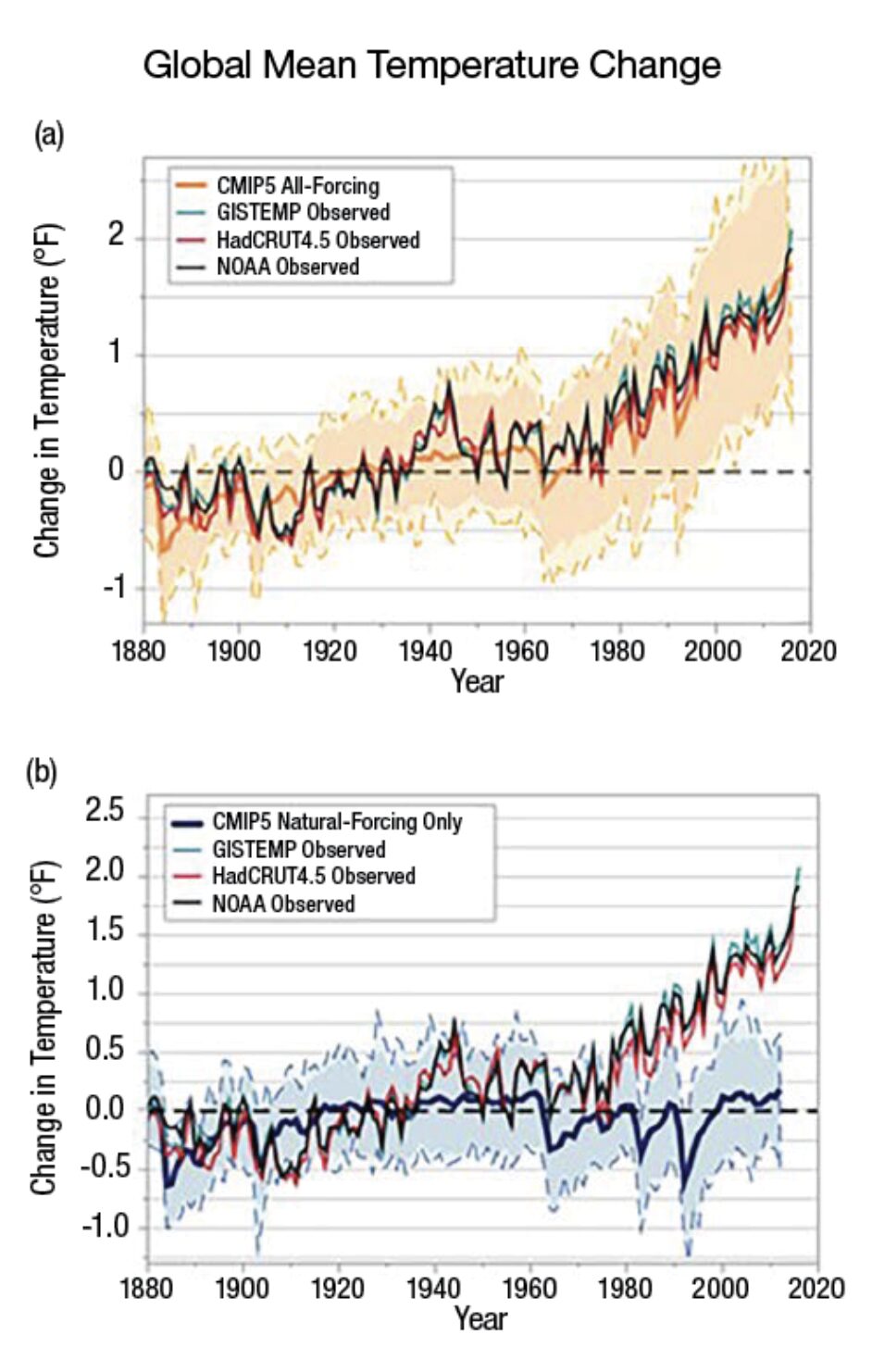
Proper science dictates that research that disagrees with the consensus should be highlighted rather than thrown aside. An investigation from 2015 found that, from a sample of 38 publicly touted papers skeptical of the scientific consensus, all 38 papers had a number of methodological flaws. When those flaws were corrected, the results of these papers aligned with the anthropogenic climate change consensus (Benestad, et al. 2015). To further illustrate the strength of this consensus, Figure 1 shows how alternative theories, like the theory that global warming is caused by natural variations in the climate, are insufficient and neither explain nor predict the future to the same accuracy as anthropogenic climate change (Wuebbles, et al. 2017). This is the scientific method in action.
This high degree of consensus is very rare in the scientific community. For example, there is still no robust consensus within the heat treatment industry on the formation mechanism of bainite in steel (Fielding 2013). Is it diffusionless-displacive? Diffusional-reconstructive? Yet, even with this uncertainty, bainite is austempered every day, producing lighter and stronger components.
The Economics of Climate Change
Similar to the level of certainty that informs today’s heat treating practices, the impacts of anthropogenic climate change are also relatively uncertain; nevertheless, the general economic ramifications are clear. A well-cited and influential study from 2024 predicted that anthropogenic climate change may cost the globe $38 trillion in damage per year by 2049. For a sense of scale, this value is 34% of global GDP in 2024, is six times more than the expected climate change mitigation costs and may lead to an overall income reduction of 19% (Kotz, et al. 2024). From a global perspective, it is the fiscally responsible decision to mitigate climate change, which consequently led 107 countries, responsible for roughly 82% of greenhouse gas emissions, to adopt a net-zero policy (United Nations 2025).
These policies result in strong financial incentives for heat treatment. The heat treatment industry is in a unique position for mitigating climate change because it can increase the strength-to-weight ratio of a material with marginal energy inputs. By reducing the total material required for a component, this optimum mitigation technique can decrease the energy and greenhouse gas emissions in all three stages of a component’s life cycle: production, use, and end-of-life.
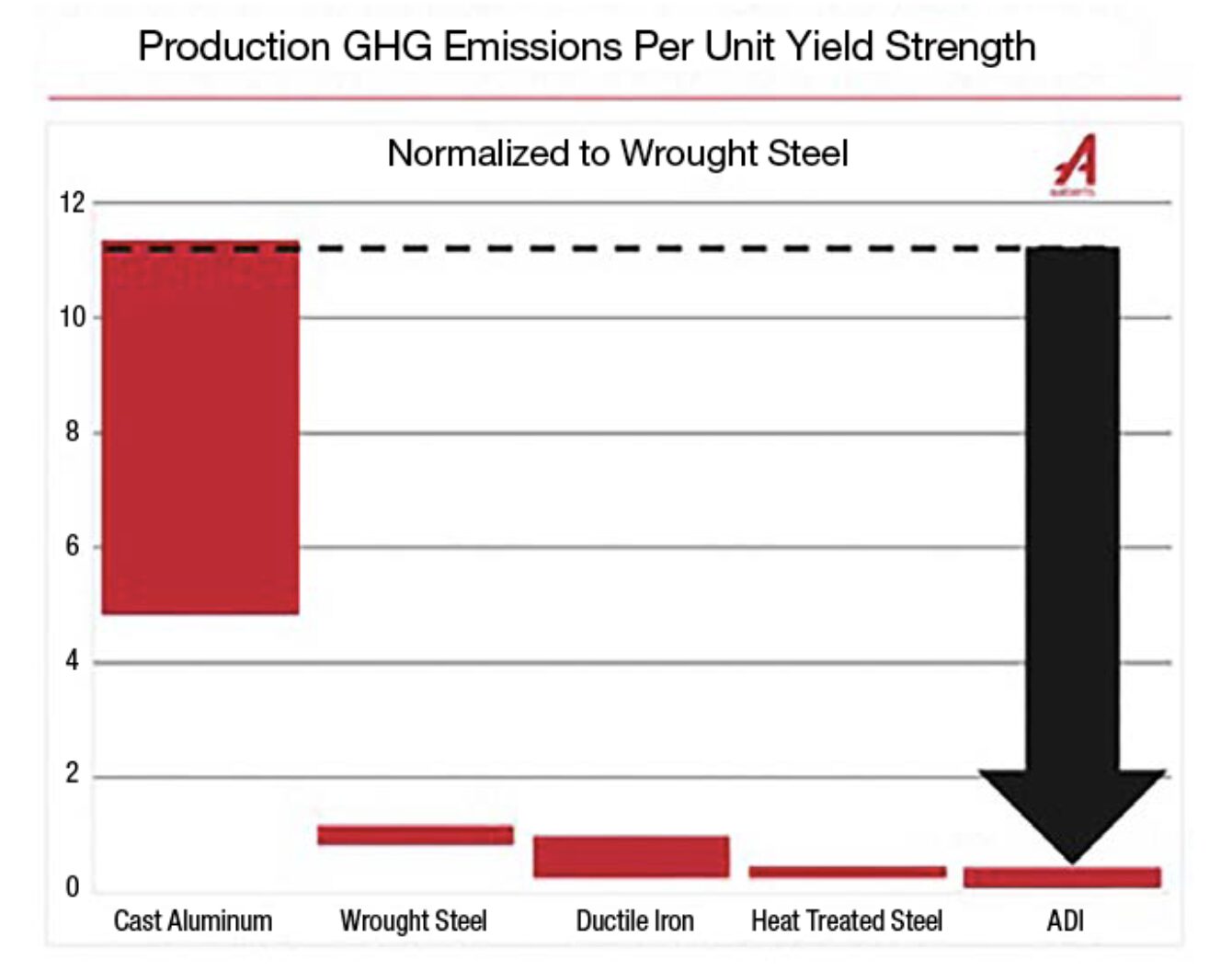
The casting industry recognized a similar opportunity and sponsored a life cycle analysis to calculate greenhouse gas emissions and the overall energy consumption for ductile iron (Zhu, et al. 2023). The study discovered that ductile iron tends to decrease the amount of greenhouse gas emissions per unit mass of material compared to competing manufacturing methods for ferrous materials. Additionally, it was revealed that Austempered Ductile Iron (ADI), a heat-treated ductile iron, can replace alternative materials on a pound-for-pound basis and further decrease greenhouse gas emissions. (In fact, ADI components could weigh more than the alternative material and still decrease greenhouse gas emissions in a lifecycle perspective). This finding can be extended to most heat-treatable materials as production greenhouse gas emissions per unit strength tend to be less than competing materials (Figure 2).
To retain this intrinsic advantage, the heat treat industry can continue to focus on decarbonization. Heat Treat Today has previously discussed a multitude of strategies for heat treaters, including electrification (Clark, et al. 2023), recapturing heat loss (Stowe 2024), enhancing furnace insulation (Roberts 2025), optimizing heat treatment processes (Buchner 2024), and utilizing hydrogen as fuel (Wolff 2024). These innovations can be explored on a case-by-case basis to balance investment with marketability to remain globally competitive.
Conclusion
To summarize, anthropogenic climate change is the prevailing scientific theory that most accurately describes the behavior of the climate. It is based on thousands of papers and studies and has survived brutal scientific and public challenges. Due to its predicted impact to the global economy, the heat treat industry is in an excellent position to become a leader in decarbonization, thereby fostering a more sustainable and prosperous future. Let’s not squander the opportunity.
References
Benestad, R. E., et al. 2015. “Learning from Mistakes in Climate Research.” Theoretical and Applied Climatology 126 (3–4): 699–703. https://doi.org/10.1007/s00704-015-1597-5.
Buchner, K. 2024. “How to Reduce Carbon Footprint During Heat Treatment.” Heat Treat Today, May 16. https://www.heattreattoday.com/how-to-reduce-the-carbon-footprint-during-heat-treatment/.
CA Governor’s Office of Land Use and Climate Innovation. 2024. “List of Worldwide Scientific Organizations.” https://web.archive.org/web/20241005030117/https://www.lci.ca.gov/facts/list-of-scientific-organizations.html.
Clarke, J., P. Kerbois, P. Sherwin, M. Pizella, A. Selvy, and S. Hakes. 2023. “Energizing the Future of Furnaces — 4 Perspectives.” Heat Treat Today, July 11. https://www.heattreattoday.com/industries/energy-heat-treat/energizing-the-future-of-furnaces-4-perspectives/.
Cook, J., et al. 2013. “Quantifying the Consensus on Anthropogenic Global Warming in the Scientific Literature.” Environmental Research Letters 8 (2): 1–7. https://doi.org/10.1088/1748-9326/8/2/024024.
Fielding, D. 2013. “The Bainite Controversy.” Materials Science and Technology 29 (4): 383–399. https://doi.org/10.1179/1743284712y.0000000157.
Glenn, D. 2025. “What If We’re Wrong About CO₂ & Global Warming?” Heat Treat Today, January 27. https://www.heattreattoday.com/what-if-were-wrong-about-co2-global-warming/.
Hornsey, M. J., E. A. Harris, P. G. Bain, and K. S. Fielding. 2016. “Meta-Analyses of the Determinants and Outcomes of Belief in Climate Change.” Nature Climate Change 6: 622–626. https://doi.org/10.1038/nclimate2943.
Kotz, M., A. Levermann, and L. Wenz. 2024. “The Economic Commitment of Climate Change.” Nature 628: 551–557. https://doi.org/10.1038/s41586-024-07219-0.
Lynas, M., B. Z. Houlton, and S. Perry. 2021. “Greater than 99% Consensus on Human Caused Climate Change in the Peer-Reviewed Scientific Literature.” Environmental Research Letters 16 (11). https://doi.org/10.1088/1748-9326/ac2966.
Roberts, J. 2025. “The Cost of Furnace Insulation Failure.” Heat Treat Today, June 23. https://www.heattreattoday.com/the-cost-of-furnace-insulation-failure/.
Stowe, M. 2024. “Sustainability Insights: How Can We Work to Get the Carbon Out of Heating? Part 2.” Heat Treat Today, March 26. https://www.heattreattoday.com/sustainability-insights-how-can-we-work-to-get-the-carbon-out-of-heating-part-1-2/.
United Nations. 2025. “For a Livable Climate: Net-Zero Commitments Must Be Backed by Credible Action.” https://www.un.org/en/climatechange/net-zero-coalition.
Wolff, D. 2024. “Water Electrolysis for Hydrogen Production Facilitates Decarbonization.” Heat Treat Today, December 17. https://www.heattreattoday.com/water-electrolysis-for-hydrogen-production-facilitates-decarbonization/.
Wuebbles, D. J., D. W. Fahey, and K. A. Hibbard. 2017. “Climate Science Special Report: Fourth National Climate Assessment, Volume I.” NOAA. https://repository.library.noaa.gov/view/noaa/19486.
Zhu, Y., G. A. Keoleian, and D. R. Cooper. 2023. “A Parametric Life Cycle Assessment Model for Ductile Cast Iron Components.” Resources, Conservation and Recycling 189. https://doi.org/10.1016/j.resconrec.2022.106729.
About The Author:

Materials Science Engineer
As a Class of 2022 Heat Treat Today 40 Under 40 recipient, Jeremy Lipshaw is an emerging leader with over 10 years of experience in the foundry and heat treatment industry. This article represents Jeremy’s passion for sustainability and scientific skepticism and is not affiliated with any current or previous employment.
For more information: Contact Jeremy Lipshaw at jeremylipshaw@gmail.com.

Reader Feedback: Heat Treat To Lead a Low-Carbon Economy Read More »