Thermocouples are ubiquitous. Whether you are 20 days or 20 years into the industry, you know the essential role they play in making sure heat treat processes are running efficiently, accurately, and dependably. This quick trivia questionnaire will test your thermocouple knowledge on a dozen either obscure or obvious facts about thermocouples.
Los termopares son ubicuos. Sin importar que tu experiencia en la industria sea de 20 días o 20 años, conoces bien el papel esencial que juegan en asegurar que los procesos de tratamiento térmico avancen de manera eficiente, precisa y confiable...
Take the English version of the quiz below, or find the Spanish translation when you click the flag above right!
If you have any facts of your own about thermocouples, our editors would be interested in sharing them online at www.heattreattoday.com. Email Bethany Leone at bethany@heattreattoday.com with your own trivia!
This Technical Tuesday article, first published in English and Spanish translations, is found in Heat Treat Today's November 2022 Vacuum print edition.
Thermocouple Trivia
1. What thermocouple type potentially has the longest life (but is also the most expensive)?
(a) Type K (Chromel-Alumel)
(b) Type N (Nicrosil-Nisil)
(c) Type R (Platinum-13% Rhodium)
(d) Type J (Iron-Constantan)
2. What is something you might find at home that uses a thermocouple to control its temperature?
Contact us with your Reader Feedback!
(a) Your oven
(b) Your toaster
(c) Your water heater
(d) All of the above
3. What do you need to know when purchasing thermocouples for your heat treat furnace or oven?
(a) The length of the thermocouple
(b) The process application you are running
(c) The type of thermocouple best suited for the
(d) All of the above
4. Who was Thomas Johann Seebeck?
(a) The person credited with describing the scientific theory behind thermocouples
(b) An advocate for the elimination of thermocouples in furnaces and ovens
(c) A German physicist who was responsible for helping develop rockets for the United States
(d) None of the above
5. What would be the best thermocouple to use to control the temperature of an oil quench tank?
(a) Type R (platinum — 13% rhodium)
(b) Type S (platinum — 10% rhodium)
(c) Type K (chromel-alumel)
(d) Type J (iron-constantan)
6. Why use an over temperature (aka "excess temperature") device on your furnace or oven?
(a) For better process control, it is always helpful to have more than one thermocouple in the furnace/oven
(b) To prevent the furnace temperature from running away and damaging the equipment
(c) An obsolete device no longer required by NFPA 86
(d) A method of ensuring the process being run in the furnace stays close to the set point temperature
7. How are thermocouples used in the heat treat industry?
(a)temperature control devices
(b) As part of a safety system designed to prevent the furnace/oven from running away and damaging itself
(c) To ensure that temperature, the most important process parameter, is maintained within limits necessary to successfully run a heat treat process
(d) All of the above
8. Why use type K versus type N thermocouples?
(a) Because type K has better accuracy
(b) Because type K has better temperature limits
(c) Because type K is more expensive
(d) None of the above
9. Thermocouples produce what type of voltage?
(a) PPM (parts per million)
(b) EMF (electromotive force)
(c) EMP (electromagnetic pulse)
(d) mV (millivolt)
10. What are some of the most common reasons why a thermocouple “drifts” or fails in a heat treat furnace or oven?
(a) Age
(b) Running at temperatures higher than its rated use temperature
(c) The wrong thermocouple type is used
(d) All of the above
11. What is a common problem seen in thermocouples that fail in service?
(a) Green rot (oxidation of chromium)
(b) Metal dusting (aka "catastrophic carburization")
(c) Grain growth
(d) All of the above
12. Complete the sentence: Types S, R, and B noble metal thermocouples are generally specified for use . . .
(a) . . . when temperatures exceed the upper recommended operating temperatures of base metal thermocouples.
(b) . . . after failing compliance on three SATs .
(c) . . . if the furnace only processes automotive parts.
(d) . . . to safeguard against low temperature readings in large loads.
Trivia Key
Compare your answers with the key on page 26 . How did you stack up in thermocouple knowledge? See where your skills measure up in the scale below.
Learn more about thermocouples in the interview between Doug Glenn and Eric Yeager on page 16 or check out the reference list below.
Heat TreatTodaywould also like to thank the following for their expert input: Dan Herring, The Heat Treat Doctor® at The HERRING GROUP, Inc.; Hank Prusinski, Summit Aerospace Products Corp.; and Andrew Bassett, Aerospace Testing and Pyrometry.
Find heat treating products and services when you search on Heat Treat Buyers Guide.com
Los termopares son ubicuos. Sin importar que tu experiencia en la industria sea de 20 días o 20 años, conoces bien el papel esencial que juegan en asegurar que los procesos de tratamiento térmico avancen de manera eficiente, precisa y confiable. Este breve cuestionario evaluará tu conocimiento de los termopares en una docena de datos entre obvios y triviales.
Si quisieras aportar otros datos interesantes relacionados con los termopares, nuestros editores te invitan a compartirlos para ser publicados en línea en www.heattreattoday.com. Puedes hacerlos llegar a Bethany Leone al correo bethany@heattreattoday.com
Thermocouples are ubiquitous. Whether you are 20 days or 20 years into the industry, you know the essential role they play in making sure heat treat processes are running efficiently, accurately, and dependably. This quick trivia questionnaire will test your thermocouple knowledge on a dozen either obscure or obvious facts about thermocouples.
Take the Spanish translation of this quiz in the version below, or see both the Spanish and the English translation of the quiz where it was originally published: Heat Treat Today's November 2022 Vacuum Furnace print edition.
Traducido por: Shawna Blair
Datos varios de los termopares
1. ¿Cuál es el tipo de termopar que más larga vida puede llegar a tener (aunque también es el más costoso)?
(a) Tipo K (chromel-alumel)
(b) N (nicrosil-nisil)
(c) Tipo R (platino-13% rodio)
(d) Tipo J (hierro-constantan)
2. ¿Cuál de estos electrodomésticos que podrías tener en casa utiliza un termopar para controlar la temperatura?
Contact us with your Reader Feedback!
(a) El horno
(b) La tostadora
(c) El calentador de agua
(d) Todas las anteriores
3. ¿Qué debes saber a la hora de comprar termopares para tu horno de tratamiento térmico?
(a) La longitud del termopar
(b) La aplicación propuesta del proceso a realizar
(c) El tipo de termopar que mejor se adapta a la aplicación
(d) Todas las anteriores
4. ¿Quién fue Thomas Johann Seebeck?
(a) La persona a la que se le atribuye la teoría científica en la que se fundamentan los termopares
(b) La persona que abogó por la eliminación de los termopares en hornos
(c) Un físico alemán responsable de apoyar en el desarrollo de cohetes para los Estados Unidos
(d) Ninguna de las anteriores
5. ¿Cuál termopar sería el más indicado para controlar la temperatura de un tanque para temple en aceite?
(a) Tipo R (platino-13% rodio)
(b) Tipo S (platino-10% rodio)
(c) Tipo K (chromel-alumel)
(d) Tipo J (hierro-constantan)
6. ¿Por qué motivo se implementaría en un horno un dispositivo de protección contra temperatura en exceso, o ¨sobre¨ temperatura?
(a) Para lograr un mejor control del proceso es favorable utilizar en el horno o caldera más de un termopar
(b) Serviría para impedir que la temperatura del horno se disparara ocasionando daños al equipo
(c) Un dispositivo obsoleto que la norma NFPA 86 ya no exige
(d) Permitiría asegurar que el proceso que se adelante en el horno se mantenga cercano al punto de temperatura establecido
7. ¿Cómo se utilizan hoy en día los termopares en la industria del tratamiento térmico?
(a) Como dispositivos de control de temperatura
(b) Como parte de un sistema de seguridad diseñado para evitar que la temperatura del horno se dispare ocasionando que el horno se destruya
(c) Como mecanismo que asegura que la temperatura, el parámetro más importante de un proceso de tratamiento térmico, no se salga de los límites indicados para lograr un resultado exitoso
(d) Todas las anteriores
8. ¿Por qué motivo se utilizaría un termopar tipo K en lugar de uno tipo N?
(a) Porque el tipo K es más exacto
(b) Porque el tipo K tiene mejores límites de temperatura
(c) Porque el tipo K es más costoso
(d) Ninguna de las anteriores
9. ¿Qué tipo de voltaje generan los termopares?
(a) PPM (parte por millón)
(b) EMF (fuerza electromotriz)
(c) EMP (pulso electromagnético)
(d) mV (milivoltios)
10. ¿Cuáles son algunas de las causas más comunes de que la calibración del termopar de un horno o caldera de tratamiento térmico se desvíe o falle?
(a) Edad
(b) Manejo a temperaturas superiores al límite recomendado
(c) Utilización del termopar equivocado
(d) Todas las anteriores
11. ¿Qué problema comúnmente se observa en los termopares que fallan en el uso?
(a) Moho verde (oxidación de cromo)
(b) Metal dusting (carburización catastrófica)
(c) Crecimiento de grano
(d) Todas las anteriores
12. Complete la frase: Los termopares de metales nobles Tipo S, R y B por lo general se especifican para uso…
(a) . . . en casos en los que las temperaturas superan la máxima recomendada para operar los termopares de metales base.
(b) . . . luego de caer en incumplimiento en tres pruebas SAT (prueba de exactitud del sistema, por sus siglas en inglés).
(c) . . . cuando la caldera solo se usa para procesos de piezas automovilísticas.
(d) . . . para prevenir que se baje demasiado la temperatura en cargas grandes.
Clave de Doce datos menudos
Compara tus respuestas de la página 27 con la clave a continuación. ¿Cómo te fue en conocimiento de termopares? Califi ca tushabilidades de acuerdo a la escala que encontrarás líneas abajo.
Para aprender más acerca de los termopares, lee la entrevista entre Doug Glenn y Eric Yeager en la página 16, o revisa la lista de obras referenciadas al fi nal de esta página.
Referencias
[1] Alexander, Colleen Stroud, et al. “Application of Ribbon Burners to the Flame Treatment of Polypropylene Films.” Platinum Thermocouple - An Overview [“Aplicación de quemadores de cinta al fl ameado de película de polipropileno.” Termopar de platino - un resumen.] | ScienceDirect Topics, 20 June 2008, https://www.sciencedirect.com/topics/engineering/platinum-thermocouple.
[2] “Introduction to Thermocouples.” A Perfect Alliance Between Expertise and Know-How [¨Introducción a Termopares. Una alianza perfecta entre la experticia y el conocimiento¨], RDC Control, 16 Dec. 2017, https://rdccontrol.com/thermocouples/thermocouples-101/introduction-to-thermocouples/.
[3] Nash, William, and Eric Yeager. “Industrial Heating Magazine: How Long Should My Thermocouple Last?” [¨Revista de Calentamiento Industrial: ¿Cuánto debería durar mi termopar?¨] Cleveland Electric Laboratories, 13 Sept. 2021, https://clevelandelectriclabs.com/industrial-heating-magazine-how-long-should-my-thermocouple-last/.
[4] Staff , Editorial. “Thermocouples Green Rot Eff ect.” [¨Efecto moho verde en termopares¨] Inst Tools, 20 Nov. 2019, https://instrumentationtools.com/thermocouples-green-rot-effect/.
[5] REOTemp Instruments. Thermocouple [Termopar], 2011, https://www.thermocoupleinfo.com/.
[6] “Thomas Johann Seebeck.” Editors of Encyclopaedia, Encyclopaedia Britannica, Encyclopaedia Britannica, Inc., 5 Apr. 2022, https://www.britannica.com/biography/Thomas-Johann-Seebeck.
[7] “What Are Thermocouples Used for?” [¨¿Para qué se utilizan los termopares?¨] Enercorp Instruments What Are Thermocouples Used for Comments, 2020, https://enercorp.com/what-are-thermocouples-used-for/. Heat TreatToday agradece la colaboración de estos expertos: Dan Herring, The Heat Treat Doctor® del HERRING GROUP, Inc.; Hank Prusinski, Summit Aerospace Products Corp.; y Andrew Bassett, Aerospace Testing and Pyrometry.
Find heat treating products and services when you search on Heat Treat Buyers Guide.com
Heat Treat Todayis launching a How Things Work periodic content series. The first topic is the basics of thermocouples. Thermocouples are the bread and butter of the heat treating world. How many of the following questions are news to you? Take a deep dive into the topic and read this question and answer session between Doug Glenn, publisher and founder ofHeat Treat Today, and Eric Yeager, director of Corporate Quality at Cleveland Electric Laboratories.
This Technical Tuesday discussion on thermocouple basics will be published inHeat Treat Today'sNovember 2022 Vacuum Heat Treating digital edition.
What is a thermocouple?
Doug Glenn (DG): In this industry, and I suppose in a lot of industries, they often refer to thermocouples as T/Cs.
Let’s start off with one of the very most basic questions: What is a thermocouple?
Eric Yeager (EY): A thermocouple is a device that measures temperature. It contains no moving parts, has no power source and it does not contain any hazardous materials like liquid mercury or anything like that.
DG: Right. That’s interesting you say that, and it’s actually good that you say that, because some of our residential consumer thermometers (which a thermocouple is kind of like a thermometer in one sense) do have hazardous materials like mercury.
EY: Absolutely, absolutely.
How does a thermocouple tell temperature?
DG: So, there are no moving parts or anything of that sort. How, exactly, does a thermocouple tell the temperature?
EY: All metals that exist, when introduced to a temperature gradient (so, if you had the length of metal A and you introduce it to a temperature gradient, which would be a difference from one end to the other) will produce a microvoltage. That microvoltage is the potential that is known as the "absolute Seebeck effect" and that’s the basis on which the single thermocouple element functions.
DG: So, when you say the single thermocouple element, what do you mean by that?
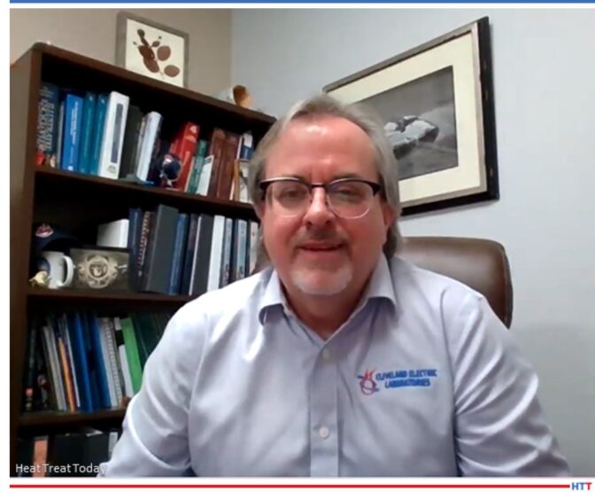
Eric Yeager Director of Corporate Quality Cleveland Electric Laboratories
EY: That would be one leg — either your positive leg or your negative leg — or it could be any actual wire that exists, and as long as you introduce a temperature gradient, it will produce some microvoltage. With thermocouples, there are set standards for what those materials are manufactured from, but any wire will create a microvoltage or an EMF output.
DG: So, let’s say we took a copper wire from our house, and we put one end on top of a candle (just for heat’s sake); you’re saying that within the span of that wire, there is going to be a voltage of some sort.
EY: Correct. And that’s actually called the "absolute Seebeck effect" or EMF.
DG: EMF, electromotive force. And Seebeck, if I understand correctly, he was the guy that discovered this stuff, right?
EY: He’s one of them. Peltier was involved and I think a gentleman named Thompson. But it was all around the same time — they kind of all collaborated with one another.
DG: You mentioned, with a thermocouple, if you have a section of wire material, add heat to one end, there’s going to be a voltage of some sort, a millivoltage in this case, a very small voltage, but a voltage, nonetheless. But you mentioned one leg. Explain more about the one leg; because, typically, isn’t there just one piece of wire in there?
EY: Right, correct. A thermocouple consists of two dissimilar metals, two dissimilar wires. For example, in a type K thermocouple, one leg would be chromel and the other leg would be alumel, and when you join those two dissimilar metals together, the net voltage between the two combined dissimilar metals is what is used to measure the output of the thermocouple. [blockquote author="Eric Yeager" style="1"]This conversion of thermal energy to electrical energy is known as the Seebeck effect.[/blockquote]
DG: So, let’s say you stick a piece of copper wire over a candle that’s burning at 400 degrees, or whatever the candle might be burning at, you’re going to get a certain voltage across there or within the wire.
EY: Along the length of that wire, yes.
DG: So, if the temperature of that candle is twice the temperature (let’s say you double the temperature of the candle) the voltage across the length of that wire is now different, yes?
EY: It’s proportional. So, the greater amount of heat energy you apply, the greater amount of EMF will be generated.
DG: And that wire, typically, for the useful life of the wire, does not change? It’s always the same? If it’s at a 100 or 1000 °F, that voltage is one; if it’s 2000, it’s that; it doesn’t ever dissipate over time, does it?
EY: No. It only degrades when a contaminate is introduced to the material.
DG: Gotcha. Because it then prevents the flow, I assume.
EY: Correct. And it’s not as pure. So, that’s one of the effects as you see something that’s called "drift" over time, over use.
Why do dissimilar materials/metals produce a millivolt signal?
DG: Now, you said, though, that in a type K, and I know that in almost all thermocouples we’ve got two dissimilar metals. If one wire can tell you an output of the voltage, why do you need two dissimilar metals in order to get a different type of voltage?
EY: It’s basically the sum of the two materials; combine the voltage generated from the entire length of the wire of the two thermal conductors.
You have to have a signal path. You have to have a source for your voltage to start and a voltage for it to end into your instrumentation. You have to have some way to read that temperature gradient and it’s typically done with two dissimilar metals to create a greater and more stable EMF.
When a lot of the cable or wire manufacturers create, say, a melt of chromel, they test that, and actually test it against a pure platinum wire so as to return the voltage back to the instrument to measure the actual EMF for the single leg output.
How important is the joining of these dissimilar metals?
DG: Now, you talked about the joining of the two dissimilar metals. How exactly how does that need to be done? Can they be welded together, and if they’re welded together, doesn’t the metal that’s used in the weld mess it up? And does it have to be just at a point, or can it be along a length that they are joined together?
Eric Yeager Source: LinkedIn
EY: It’s important to have the purest, most secure junction when joining the two dissimilar metals. It’s typically done by welding the metals together without adding any filler material. That’s especially important when you have something that has a very low EMF output, which is like your noble metal thermocouples. That’s where purity is essential. Loose connections from twisted or crimped junctions also might cause intermittencies under thermal expansion and affect the thermocouple output signal.
DG: So, typically, they are welded together without a filler; they’re just welded together.
EY: Correct. You just bring a TIG torch in, give it a quick zap, and it melts the two wires together. Once you get that nice little joint or junction, you can run and complete the assembly.
DG: Okay. We already talked about why there are different millivolt readings at different temperatures, because basically it’s the difference in the heat.
EY: Correct. As the temperature increases, there’s a direct correlation to the microvoltage output from that particular wire or wire pair.
DG: And I asked about how important are the joining of these materials. Typically, you don’t want it over a wide section, right? Does it matter if it’s a spot weld, instead? What would happen if you had one that was an inch or two inches long? Is that a big deal?
EY: It’s best to keep it as small and concise as possible, because it could form a heat sink later on when you’re in application; typically you just want a small nice round junction. For example, you want the junction to be about twice the diameter of the single thermal element. So, if it was a 20 thousandths-diameter wire, you want it 40 thousandths in diameter.
Thermocouples welded to a workload; wouldn’t that weld introduce some “interference” in the millivolt signal?
DG: Aren’t some T/Cs welded? I think I’ve heard that sometimes they’ll take thermocouple wire that will be joined and then welded to, or in some way applied right to, a load. If you were applying it directly to a workload, wouldn't that extra metal kind of mess up the millivolt?
EY: You would think so, but as long as they’re kept as close as possible, and the workpiece that you’re welding to is kept isothermal or actually uniform in temperature between the two welded junctions, it won’t have a detrimental effect on the thermoelectric output. [blocktext align="right"]But you want to make sure that the workpiece is uniform in temperature because you have a temperature gradient across where those two junctions are welded to the material, and it can have a slight effect.[/blocktext] That’s essential to basically ensure that your workpiece is isothermal.
DG: What do you mean by isothermal?
EY: Uniform in temperature across the entire workpiece between the welded beads. The workpiece will become the welded bead, but it won’t create any additional EMF output to the combination because it’s the combination of the length — it measures the temperature across the entire length of the wire not necessarily at the bead.
It’s kind of a common misconception that the bead creates all the EMF, but it’s actually along the length of the wire.
DG: It is along the length of the wire. I always thought that the temperature was measured basically at the bead, at the joint.
EY: Well, that’s where it starts, but it’s combined along the length of the wire.
In the heat treating world, what is the most popular T/C and what are the materials from which it is made?
DG: So, in the heat treat world, what’s the most popular T/C and what are the materials it’s made from?
EY: I would say it’s definitely the type K and those two materials are chromel and alumel as we previously discussed. It’s probably the most popular due to the low cost and the wide temperature range capability. Basically, you can go from 32°F all the way up to 2450°F. It won’t last very long at those temperatures, but it’s the most common and the most versatile. I would say type K is the most popular.
How long do type K thermocouples last in a furnace/application?
DG: The factors: you were talking about them not lasting all that long. This is probably a loaded question, but if you’re in an average heat treat application, what’s a typical lifespan of a type K?
EY: To be honest with you, that’s the question that everybody wants to know. And truthfully, it depends on the application. It depends on thermal cycling, it depends on how well the thermocouple thermoelements are protected from the environment, for example, whatever protection tube you put it in, if it’s an MGO, or an exposed bead. All of those things are contributing factors. Really, it’s very, very application dependent. For example, I’ve seen type K control thermocouples last for 5 years but that’s basically at a stable temperature without any thermocycling and a constant, nice, clean environment. But I’ve seen units that get consumed rapidly at the elevated temperatures, like I mentioned, 2450°F. They don’t last very long there but they do measure.
DG: So, the undesirable conditions for those things would be a lot of thermocycling up and down, so, it’s going to fail faster, I assume?
EY: Correct. And temperature of course: the higher temperature, the greater degradation in the material. That pretty much stands for any thermocouple type.
DG: I want to ask a couple questions that aren’t on here just because I’m curious about this. A lot of times, you’ll have the spot weld where you put them together, that’s called the bead?
EY: Yes. Or junction. Either/or.
DG: So, the bead or the junction — that’s obviously bare wire, right? Assuming we’re actually using to put it on a workpiece. You’ve got the bead and then you’ve got, obviously, a little bit of bare wire at least. Is the rest of that wire covered or is it often not covered?
EY: It must be covered because it could short somewhere along the length of the wire. It could be either a soft wire insulation, like a ceramic fiber or a REFRASIL® or even a fiberglass-type insulation depending upon the temperatures.[blockquote author="Eric Yeager" style="1"]What I actually prefer is an MGO-style thermocouple where it has a metallic outer sheath surrounded by a magnesium oxide insulator that prevents it from shorting out.[/blockquote] So, for example, if you just ran straight wire and had any kind of airflow or thermal expansion, it could short out somewhere along the length of the wire. Basically, a thermocouple will measure from the closest measuring junction to the instrumentation. Therefore, if it’s shorted out, you’d get a false reading.
DG: So, if you had it attached to the load and it runs over here but it touches something else just before it goes out to the outside of the furnace or whatever, you’re going to measure that spot closest to the temperature wall, so it doesn’t give you anything on the load.
EY: What’s very common is people will run the software thermocouples through a door of a furnace where it closes on the door, that’s where it shorts out.
What are some of the factors that will affect the longevity of a T/C? What is the most common cause of failure?
DG: What are the most common causes of failure? Did you have any others besides that we just talked about the door one?
EY: For control thermocouples, like your type R, S, or B, those are subject to contaminates more than the other types. They’re more susceptible to carbon, graphite, silica, and those type of things. So, when you have an assembly like that, like a control thermocouple in a furnace, you have to ensure that it’s properly protected from the environment to which it’s exposed to allow it to have the greatest longevity. There are different sheath materials that you can put the thermocouples in: alumina, it could be silicon carbide tubes, all kinds of different varieties.
DG: You want to keep the environment, the atmosphere out of it and all that good stuff.
EY: Real quick, Doug: You mentioned control thermocouples. If you had like a type R or S control thermocouple and it was exposed to something that was going to contaminate it, what typically happens when a thermocouple fails? The EMF output of the thermocouple is degraded. What that would actually cause is it would cause your furnace to call for more heat because the EMF was degraded. Even if it’s a few degrees, that might cause an overtemp condition when you have very tight requirements on a thermal process.
DG: Right. And then, hopefully, your overtemp thermocouple would kick in and say, “Wait a minute!”
EY: Yes, that’s exactly right. Hopefully, you don’t have it set too high.
How can you tell when your T/C is going bad? Drift, etc.?
DG: How can you tell when your T/C is going bad and could you talk about drift?
EY: The best way to determine if your thermocouple is going bad is to perform regular system accuracy tests. Those tests, will allow you to track the lifecycle of the thermocouples and determine when they begin to drift and when it’s time to remove them from service. Unfortunately, when a thermocouple drifts, there is not adjustment knob on it; you can’t fix it. Once it starts going, it goes, and you just have to replace the assembly.
When thermocouples drift, they typically drift negative. They will see less of a temperature due to the contaminates getting into the material and altering the EMF output of the thermocouple. So, your control will essentially ask for more heat, and that’s where you end up having the problem. That’s why it’s essential to perform your SATs and maybe set up a little PM schedule for your system to know that you're experiencing "x" many life cycles out of the thermocouples before they fall out of your requirements, and so maybe every "x" months you have to replace the assemblies and install new ones.
Because of the drift, the best thing you can do is perform a system accuracy test with a thermocouple that has not been subject to long exposure at temperature.
Dissimilar metals and EMF?
DG: I want to go back to the two-wire thing because I don’t quite understand that. I’m not an engineer guy so see if you can explain. You’ve got the one wire that has an EMF in it, but I still don’t quite get why we use dissimilar metals to create the EMF.
EY: The summation of the voltage between the two thermocouples that provides the set EMF. The set EMF, is determined by the international temperature scale ITS-90 scale; that sets all the microvoltages for the thermocouples. It’s designed as a paired thermocouple group not as a single element. With a single element, you really would not have a good way to return the signal to your instrument.
Both wires conduct the voltage back to the instrument; one is a positive and one is a negative. Since it is a direct current (DC) voltage, one leg provides the negative path and one leg provides the positive path.
DG: Ok, so there’s a millivoltage signal being sent back to the instrument, which is reading that millivolt and then converting it based on what type of thermocouple is out there; and it’s recording that reading and turning it into a temperature.
About our expert:
Eric Yeager is the director of Corporate Quality at Cleveland Electric Laboratories. He's been with Cleveland Electric Labs for 17 years and is working on year 18. In that time, he has been director of quality and runs their accredited thermocouple calibration laboratory. Eric is involved with ASTM and is a subcommittee chairman for E2011, which is the calibration section of the thermocouple standards. He also was technical consultant on some of the rewrite of the latest AMS2750.
Find heat treating products and services when you search on Heat Treat Buyers Guide.com
Readers are checking out recent AMS2750 Rev. G changes and want some more information from Heat Treat Today about a specific clarification. Read the correspondence about the implications of AMS2750 Rev. G paragraph 3.1.1.5 about how to measure junction construction.
Douglas Shuler, lead auditor at Pyro Consulting, has written numerous articles with Heat Treat Today about AMS2750 standards. Check them out by searching "Doug Shuler" at www.heattreattoday.com.
READER QUESTION: After combing the new AMS2750 Rev. G, I found that paragraph 3.1.1.5 no longer allows thermocouples to be tack welded directly to parts, OR to representative dummy parts. This has been standard practice for decades. So I dug into it further with the folks from PRI and it turns out to be true. They’re now expecting load thermocouples to be either placed inside of a part (ends twisted and inserted), or inside the hole of a dummy block.
I’d done some searching online and there isn’t a single source talking about this major change. This could lead to a lot of failed upcoming Nadcap audits.
Doug Shuler Lead Auditor Pyro Consulting
Douglas (Doug) Shuler (Pyro Consulting) for Heat Treat Today: Historically (i.e. prior to Rev. F), AMS2750 was silent on measuring junction construction. In Rev. F, the construction of the measuring junction was as follows:
Measuring junctions shall be made by any combination of twisting and/or welding the thermal elements provided there is no addition of filler metal.
This raised concerns about both the use of quick tips and spot welding to make the measuring junction. The AMEC AMS2750 revision team engaged with Cleveland Electric Laboratories to perform testing on these measuring junctions as compared to the twisting/welding combinations.
The conclusion of the tests were that both quick tips and spot welding to a part/heat sink became unstable at temperatures above 2000°F. The quick tip crimping point and the spot welds showed rapid oxidation and increased errors in a short period of time. Based on the results of these tests the AMEC AMS2750 revision team put forth the following update in Rev. G:
Measuring junctions shall be made by either of the following methods:
Any combination of twisting and/or welding the thermoelements provided there is no addition of filler metal (including ungrounded and grounded MIMS).
Spot welding the thermoelements directly to a part, simulated part, or heat sink is permitted for temperatures ≤2000°F or 1100°C.
This allows spot welding measuring junctions for process temperatures at or lower than 2000°F. The team and AMEC members decided that quick tips were to unstable to permit their use going forward.
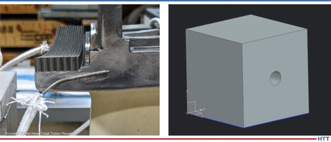
READER FOLLOW-UP: Our current method that we’re using is to twist the thermocouple using a set of Twister Pliers, then tack-weld that twist onto the part (first photo below). We’ve been doing this for parts up through brazing temperatures (~2150°F) without issue. We recently ran a furnace run around 2100°F with parts tack-welded as I’ve described AND had T/Cs that were just twisted with no tack weld. We noticed there was no significant difference in the temperature the TCs were reading. This was also our technique that we used at my previous company.
The way I read AMS2750 Rev. G was: You may twist and weld thermocouples to a part, but only for temperatures less than or equal to 2000°F.
To comply with Rev. G, we have gone ahead and made heatsink blocks to make sure we’re in compliance. Our new method of temperature measurement is twisting the wires and sticking the twisted end down inside of a block of solid metal (like the one I’ve shown below).
Source: Heat TreatToday Reader
We welcome your inquiries to and feedback on Heat Treat Today articles. Submit your questions/comments to editor@heattreattoday.com.
At Heat TreatToday, we want to make sure everyone in the North American heat treat industry is well informed so they can be happier and make better decisions. With that in mind, we have been growing our library of Spanish heat treating content.
Below, click the blue headings to learn from Víctor Zacarías about pyrometry standards in the aerospace and automotive industries, from Carlos Carrasco about selecting heat treating equipment, from Bill Munn about leadership and motivation, and from Erika Zarazúa about CQI-9's probe method A. If you'd like to view this content in English, click the America flag icon.
Víctor Zacarías General Director Global Thermal Solutions Mexico
"Las operaciones de tratamiento térmico son percibidas generalmente como cajas negras cuyos resultados son poco predecibles. Si bien, entendemos los mecanismos físicos involucrados para modificar las propiedades de un material, los hornos de tratamiento térmico son sistemas termodinámicamente imperfectos, y por ende los resultados finales en ocasiones también lo son."
Contact us with your Reader Feedback!
"Heat treatment operations are generally perceived as black boxes whose results are not very predictable. Although we understand the physical mechanisms involved in modifying the properties of a certain material, heat treatment furnaces are thermodynamically imperfect, and sometimes the final results are too."
This article first appeared Heat Treat Today's March 2022 Vacuum Furnace print edition.
Carlos Carrasco Founder Carrasco Hornos Industriales
"Este artículo ayuda a los ingenieros a comprar equipos de tratamiento térmico. Hay muchas razones para seleccionar cuidadosamente los hornos industriales. Uno, es el costo del horno en sí y otro, es que el producto que se está tratando térmicamente afectará los resultados de su empresa."
"There are many reasons to select industrial furnaces carefully. One is the cost of the furnace. Another is realizing heat treating will affect the product and the bottom line. There is more specialized engineering in heat treating equipment than is apparent from the outside."
This article first appeared in Heat Treat Today's November 2021 Vacuum Furnaceprint edition.
Bill Munn Leadership Coach Bill Munn Source: Bill Munn Coaching
Por definición, de aquí se desprende que no se desempeña solo; es más, está posicionado no solo para trabajar en conjunto con otros seres humanos sino también para liderarlos; si su potencial se ha de realizar, puede que ya haya entendido bien que en esas personas reposa la verdadera clave del éxito que a futuro pudiera conseguir ¿Cómo, pues, lograr su compromiso?
By definition, this means that you are not functioning alone. Moreover, you are positioned not only to work with fellow human beings, but to lead them. And if your potential is to be realized, you may already know well that those people are the true key to your future success. So how will you engage them?
This article first appeared in Heat Treat Today's September 2022print edition.
Erika Zarazúa Regional Purchasing Manager Global Thermal Solutions México Source: Global Thermal Solutions México
"Las pruebas SAT deben realizarse a todos los sistemas de control, monitoreo y registro de los equipos de procesamiento térmico. Esto no aplica para los sistemas de ‘alto-límite” cuya única función es la de proteger al horno de un sobre calentamiento."
"System Accuracy Tests (SATs) must be performed on all control, monitoring, and recording systems of thermal processing equipment. This does not apply to “high limit” systems, whose sole function is to protect the furnace from overheating."
This article first appeared in Heat Treat Today's August 2022 Automotive print edition.
Find heat treating products and services when you search on Heat Treat Buyers Guide.com
Some thermal sensing systems are not able to measure the lower end of the spectrum, while other systems are not able to measure the higher end. In Part 1, we learned how Nanmac and Rhenium Alloys, Inc. worked together to discover a thermal sensing system in hydrogen atmospheres that answered these issues.
In Part 2, explore thermal sensors in hydrogen atmospheres for temperatures above 2642°F to discover if ceramics can reach 4000°F. Can these ultra-high temperature systems be built commercially?
Today's Technical Tuesday was written by Herbert Dwyer, chief technical officer of Nanmac and president of Herb Dwyer & Associates, LLC.; Todd Leonhardt, metallurgist and director of Research & Development at Rhenium Alloys, Inc.; and Joe Johnson, senior metallurgical technician at Rhenium Alloys, Inc. This article was originally published in Heat Treat Today’s March 2022 Aerospace Heat Treating print edition.
Joe Johnson Senior Metallurgical Technician Rhenium Alloys, Inc. Photo Credit: Rhenium Alloys
Herbert Dwyer CTO, Nanmac President, Herb Dwyer & Associates
Todd Leonhardt Metallurgist and Director of Research & Development Rhenium Alloys, Inc.
Introduction
Temperature sensors for use in stationary or aviation turbines and/or test stands must also work in high wind shear, thermal shock, mixed gas environments and vibration which add more challenges. Key sections of the turbine, that contribute to the increased efficiency of the turbine operation, require higher temperatures than the traditional 2642°F (1450°C) to be measured. No thermocouple exists that can make these measurements reliably today. Theoretically, the temperature has been calculated to be near 4262°F (2350°C).
While there is significant history of using optical pyrometers above 2642°F (1450°C), the optical pyrometer is not practical on the actual turbine or in the test stand. The PIWG (Propulsion Instrumentation Working Group) consortium developed a matrix that added a requirement for directly measuring the hot section of the turbine to 4262°F (2350°C).
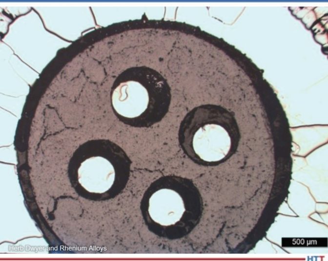
Figure 1. W5Re/W26Re wire with an alumina insulator and molybdenum sheath Photo Credit: Herb Dwyer and Rhenium Alloys
To get the most useful result, we combined the insulator (a form of ceramic), the sheath (molybdenum), and the Type C wire, tested them and then performed a full lab analysis after each test period. The various step temperatures are shown in Figure 1 and started at 3362°F (1850°C) and the exposure time varied from one to six hours and compared this thermocouple assembly to a calibrated pyrometer in the same hydrogen-based atmosphere furnace. Our previous testing showed that a better understanding of the interactions between these materials was critical to longer life and performance at these UHT ranges. Our lab analysis also looked at both the mechanical and the chemical properties of these interactions as well.
This turns out to be a significant challenge because of the interaction of the material systems that cause the resulting eutectic temperatures to be much lower than their individual temperature ratings. This includes: the ceramic insulators, refractory metal sheath, and W-Re wires. A key question now is, are we approaching the material systems maximum capabilities? Further testing up to 4172°F (2400°C) is planned in 2022 to determine that answer. In addition to the material requirements, the real questions include: how accurate are these direct reading thermocouples and can they be calibrated at these UHT (Ultra-High Temperatures); what is their overall life and what are the drift factors?
Generally, the ASTM E230 Table for the Type C wire shows an accuracy of +/- 1% up to the maximum of 4199°F (2315°C). Earlier tests by the National Institute of Standards and Technology (NIST) showed that the typical accuracy of the Type C assembly (in this case the wire and its insulators only, not the sheathed versions) above 3182°F (1750°C) starts to degrade from those shown in the E230 Table. The accuracy may be closer to +/- 1.5% which at these temperatures may become a critical determiner for the life and maintenance costs. While we used a Type C wire supplied by a highly recognized manufacturer for our test program, our emphasis was to address the insulator since it was the weaker link in the overall assembly.
Nanmac set a goal to achieve the ASTM E230 Table accuracy of +/- 1% or better up to the maximum of 4199°F (2315°C) with the insulator life being analyzed. In addition, they have set their sights on developing a direct comparison measuring system by using a NIST traceable optical pyrometer calibrated and a NIST traceable thermocouple for Ultra-High Temperature measurements. NIST has previously used this type of system.
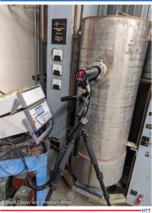
Experimental Setup
The temperature measuring experiments used a 33 KVA Spectra-Mat furnace which has three tungsten rod elements for heating as shown in Figure 2. The outer bell and pedestal are water cooled to prevent overheating during operation. The heating elements are surrounded on the outside diameter by a multilayer of 0.009” thick molybdenum sheet as shown in Figure 3. The NIST traceable thermocouple is fed through the pedestal and attached via molybdenum clamp above the pedestal shown in Figure 4. The thermocouple is centered in the hot zone to provide uniform temperature. The calibrated NIST traceable optical pyrometer is set at a specific distance from the quartz window imbedded into a water-cooled bell. The optical pyrometer is aimed 1.0” below the tip of the thermocouple and the emissivity is set for molybdenum, since the thermocouple sheath is molybdenum as shown in Figure 2. The optical pyrometer output was adjusted for the reflection angle, spot location, spot size, and to ensure that it was perpendicular to the assembled thermocouple, because these were identified as the critical variables for this calibration process.
By running the optical pyrometer/thermocouple experiment several times, it was demonstrated that this combination of a thermocouple and pyrometer can give reliable and repeatable comparative data as shown in Figures 5 through 7.
Figure 2. Tungsten heating elements with thermocouple placed in center of hot zone. Photo Credit: Herb Dwyer and Rhenium Alloys
Figure 3. Molybdenum shield package with sight hole over tungsten heating elements. Photo Credit: Herb Dwyer and Rhenium Alloys
Figure 4. Spectra-Mat furnace with optical pyrometer and thermocouple for temperature measurement. Fluke data logger to record out-put of both instruments. Photo Credit: Herb Dwyer and Rhenium Alloys
Figure 5. Optical pyrometer versus thermocouple to compare temperature measurement. The blue line is optical pyrometer data and yellow line is the thermocouple temperature data. The optical pyrometer starts reading at 800° (1472°F). Photo Credit: Herb Dwyer and Rhenium Alloys
Figure 6. Optical pyrometer versus thermocouple for run 2-1600°C which compares temperature measurement techniques. The blue line is the optical pyrometer data and yellow line is the thermocouple temperature data. The optical pyrometer starts reading at 800°C (1472°F). Photo Credit: Herb Dwyer and Rhenium Alloys
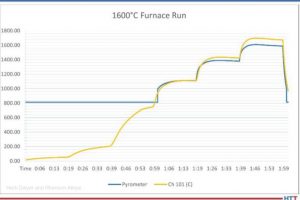
Figure 7. Optical pyrometer versus thermocouple for run 3-2000°C which compares temperature measurement techniques. The blue line is the optical pyrometer data and yellow line is the thermocouple temperature data. The optical pyrometer starts reading at 800°C (1472°F). Photo Credit: Herb Dwyer and Rhenium Alloys
The furnace is increased in power in timed set points (steps) which show up on the graph as temperature versus time. Experiments were run at 2912°F (1600°C) and 3632°F (2000°C). As shown in the graphs, the yellow line (thermocouple) tracks these step point changes as the power is increased. The blue line (optical pyrometer) starts at 1472°F (800°C) since the optical requires color to measure temperature. After 1472°F (800°C) both thermocouple and optical pyrometer track temperature well. At the 2912°F (1600°C) the optical pyrometer was reading slightly lower temperatures than the thermocouple in all experiments at the higher temperatures.
It is believed that this is caused by the thermocouple reading the combination of convective, conductive, and radiated thermal energy while the pyrometer is responding to the radiated energy as potentially attenuated by the hydrogen gas atmosphere.
While the Type C matched legs (W5Re/W26Re) wire, according to the ASTM E230 Table, covers a range from 32°F to 4199°F (0°C to 2315°C) the initial test furnace was limited to a range of 1472°F to 3632°F (800°C to 2000°C) due to the type of insulator being used in this experiment.
The next set of experiments will have an operational temperature of 3992°F (2200°C) with the same ramp rate holding the same variables. In the near future, Rhenium will use a front loading Centorr furnace which is rated up to 4532°F (2500°C), but for now, tests up to 3992°F (2200°C) are planned in 2022. The experiments helped to identify key elements of the assemblies and suggested additional long duration tests that will address each element in more depth. These experiments are ongoing as of this Part II article and further reports of the results will be published over the next year.
Our tests used different types of insulators rated at these temperatures and after the tests, we performed a cross sectioned lab analysis to determine the interaction of these insulators with the wire and sheath.
Comparison of the Assembled Thermocouple and the NIST Traceable Pyrometer Output Curves
As the curves indicate, it is possible to directly compare the output of the Type C based thermocouple to the NIST traceable pyrometer, and, after some experimentation, we were able to develop a repeatable process which showed that the pyrometer tracked the assembled thermocouple.
Using this approach, we more realistically determined the actual accuracy of the assembled thermocouple under UHT and hydrogen atmospheres. Our life testing has achieved 100+ hours and these tests continue.
Typical Applications of These Types of Assembled Thermocouples
Ultra-high temperature sintering and alloying of unique material(s) is used in turbine blades; hypersonic vehicles; space craft; nuclear reactors.
Ultra-high temperature furnaces where critical temperature measurements at these elevated temperatures are important (tantalum materials for capacitors etc.).
Very high temperature section of the stationary or aviation turbine where true temperature measurements, at UHT up to 4262°F (2350°C) can help to plan maintenance, contribute to life cycle calculations, and enable the optimization of the turbine’s combustion efficiency.
Replacement of the Type S (platinum-rhodium), Type R (also a platinum-rhodium), and a Type B (platinum-rhodium). These are short lived at temperatures above 3002°F (1650°C) (and, in the case of the Type B, has a limited lower temperature measuring range of 1112°F (600°C) due to its low millivolt output).
The Type C output at 1112°F (600°C) is 10.609 MV or almost 6x greater than that of the Type B (1.792 MV) allowing more accurate temperature measurement. The Type C at 572°F (300°C) has an output of 4.865 MV or almost 3x that of the Type B at 1112°F (600°C) enabling a wider temperature measuring range at a much lower total cost and a more robust temperature measurement.
About the Authors:
Herbert Dwyer is the CTO of Nanmac, and president of Herb Dwyer & Associates, LLC. Herb specializes in international business development, electromechanical manufacturing, heat treating furnace optimization, and thermal measurements up to 4172 °F. Herb has over 50 years of experience in the field of thermal and pressure sensors for the aerospace industry.
Todd Leonhardt, a metallurgist and director of R&D at Rhenium Alloys, Inc., possesses an in-depth knowledge of high temperature refractory metal and is an expert in rhenium. As a 38-year veteran of industrial and government research in the areas of material characterization and processing refractory metals, Todd has shared his knowledge in over 25 publications including NASA technical memorandum, peer review journal articles, and conference proceedings.
Joe Johnson is the senior metallurgical technician at Rhenium Alloys, Inc. and has been working with refractory metals, specifically rhenium and its alloys, for over 15 years. While his background is in material processing, most of his tenure has involved process metallurgy. In addition to co-authoring several technical publications, Joe enjoys performing failure analysis and designing custom tools and equipment.
Direct thermal measurement of temperatures within a turbine is limited due to many factors. Some thermal sensing systems are not able to measure the lower end of the spectrum, while other systems are not able to measure the higher end. In this article, learn how Nanmac and Rhenium Alloys, Inc. worked together to discover a thermal sensing system in hydrogen atmospheres that solved these issues and more.
Today's Technical Tuesday was written by Herbert Dwyer, chief technical officer of Nanmac and president of Herb Dwyer & Associates, LLC., and Todd Leonhardt, metallurgist and director of Research & Development at Rhenium Alloys, Inc. This article was originally published in Heat TreatToday’s December 2021 Medical & Energy print edition.
Introduction
Todd Leonhardt
Metallurgist and Director of Research & Development
Rhenium Alloys, Inc.Herbert Dwyer
CTO, Nanmac
President, Herb Dwyer & Associates
Direct thermal measurement of temperatures within the turbine (both fixed and aviation) and on the test stand, has been limited to 2642°F (1450°C). This uses a precious metal thermocouple composed of platinum (Pt) and rhodium (Rh) which are very expensive and have limited life above 3182°F (1750°C).
The conditions within the turbine also limit the choice of direct measurement systems due to the combustion by-products, wind speeds, pressures, shear forces, vibration, and thermal shock.
The recent focus on “green energy” gases that are more friendly to the atmosphere and offer excellent energy density per volume of gas points to a gas that has been around for many years — hydrogen. However, the use of hydrogen as a combustion gas within the turbine can be challenging as well. Molecular hydrogen is generally smaller than molecular oxygen. The by-product of the combustion of hydrogen and oxygen forms water. Water vapor is more climate friendly than carbon monoxide, carbon dioxide, or other forms of carbon found in turbines using standard jet fuels, natural gas, or combinations. Another challenge is the wide variety of temperatures to be measured at various points within the turbine, from inlet air to combustion to outlet air, the range can be from -22°F (-30°C) or lower to a predicted high of 4172°F (2300°C). No one type of thermal measuring system exists today that covers this total range. With this as a baseline, Nanmac and Rhenium Alloys, Inc. worked together to explore various combinations of material systems that could operate at the lower temperatures, plus reaching the upper temperatures of 4172°F (2300°C).
The system that could cover this range was the Type C thermocouple with a 5% tungsten and 26% rhenium wire composition. One key part of the system is the insulator which separates the two legs of the thermocouple, the second key part is the refractory sheath like tantalum or molybdenum. The range of temperature covered by this combination was from about 662°F (350°C) to 4172°F (2300°C). The actual testing temperature was performed from 1292°F (700°C) to 3992°F (2200°C).
Application and Testing Objectives:
Fixed and aviation turbines (includes direct mount and test stands)
Test temperatures above the 2642°F (1450°C) range
100% hydrogen atmospheres
Thermal shock issues
Life issues at elevated temperatures and stress
High shear stress caused by air flow
Low and high frequency vibrations
Mounting options to accommodate space issues
Atmospheric corrosion caused by particulates in combustion gases
Cold junction transition location
Mounting depth
Objectives, Equipment, Assembly, and Test Times
Of concern, as atmospheres approach the ultra-high temperatures (UHT) region above 2642°F (1450°C), there are materials interactions between the components of the thermocouple (sheath, insulators, and thermocouple wires) and the furnace environment (representing the combustion section of the turbine) at elevated temperatures. Individually, the materials have high melting points, but combining these materials within the thermocouple system can cause low melting point eutectic to form a reaction between materials to occur. These material interactions can cause the thermocouple to fail prematurely in service at unexpectedly lower temperatures than predicted.
During Nanmac’s material compatibility testing, interactions between the sheath, insulators, and Type C thermocouple wire occurred. The weak link in the thermocouple system is the high temperature insulators of hafnia, alumina, and boron nitride. As the temperature approached the 3812°F (2100°C) test temperature, the insulators decomposed. Some of the observed failures appeared to be due to the hydrogen gas penetrating the end closure welds or even through the sheath walls; some of the insulators failed at these temperatures at much lower levels than expected. Some failure modes were caused by the insulator melting and attacking the thermocouple wires leading to fractures of the junction welds and the individual thermocouple wires.
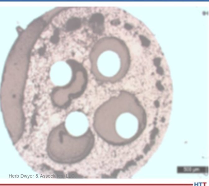
Figure 1. The hafnia insulator failed above 3542°F (1950°C)
Photo Credit: Herb Dwyer & Associates, LLCFigure 2. 99 alumina failure above 3542°F (1950°C) during the transition to 3812°F (2100°C) 6 inches back from tip
Photo Credit: Herb Dwyer & Associates, LLC
Nanmac and Rhenium Alloys, Inc. used hydrogen cover gas because of access to a furnace which used that atmosphere. The use of hydrogen as a future combustion gas gave insight into how these material systems would operate in that harsh environment. The furnace also gave insight into the thermal shock issues from quenching the furnace with hydrogen gas for rapid cooling which allowed for a quick turnaround in testing. Additionally, the processes helped evaluate the possible impact of 100% hydrogen atmosphere on the insulator’s materials, wire junction welds, and sheath end closure weld. The furnace used for compatibility testing used a calibrated control system with a reference thermocouple and a calibrated optical pyrometer.
The test assemblies for compatibility testing were smaller lengths of typical thermocouple systems composed of the 0.050” walled molybdenum sheath. The insulators tested included: hafnia (HfO2); 99% alumina (Al2O3), and boron nitride (BN insulator and Type C 24 AWG [0.020]) thermocouple wire assembly, which was back filled with argon gas to prevent oxidation of the components. Test durations were one hour, two hours, and six hours, at elevated temperature and a complete post-mortem evaluation was performed on all test articles to evaluate compatibility of the thermocouple components at UHT.
Discussion:
The ASTM E20 Committee is exploring the possible increase in calibration temperatures from the existing 2642°F (1450°C) to 3182°F (1750°C) or higher. While it appears the individual materials can achieve these and even higher temperatures, tests indicate that this is not the case for all the combined thermocouple components.
Discussion of some of the material issues includes:
1. As atmospheres reach 3182°F (1750°C) and up to 4172°F (2300°C), materials are limited to refractory materials like:
Molybdenum, tantalum, platinum, and other alloys of these materials.
Ceramics like 99% alumina, zirconia, hafnia, boron nitride, silicon nitride (SiC), and others were tested.
Wire materials are limited to some alloys of tungsten (W) and rhenium (Re).
2. Combining these materials also lowers the system’s overall temperature. For example, the boron nitride, on its own, can reach temperatures up to 5252°F (2900°C), but when combined with the Type C wire and molybdenum sheath, it can only operate reliably to 3632°F (2000°C). Figures 1 and 2 are examples of failures of ceramic insulator exposed to high temperature service conditions.
NOTE: During lab analysis, at the various temperatures, it was observed that decomposition and significant degrading of the insulators had occurred. The exposure to the UHT not only attacked the ceramic insulators but also attacked the Type C wire and its sheath. Part two of this article will show some of the pictures of this attack and discuss some of the approaches to address this material issue at these UHTs, above the threshold of 3182°F (1750°C).
3. Cost now becomes a significant driver. Some of these materials, including alloys of platinum and rhodium can cost upwards of $2,000 or more per inch, are very hard to machine and form, and can contain hidden cracks and voids that under these extreme temperatures lead to reduced mechanical life.
4. The operating atmospheres have a significant impact on the alloys used, and high carbon loads from unburned fuel can also impact these refractory materials, for example:
Oxygen attacks molybdenum, tungsten, and even tantalum, although to a lesser extent than the attack on molybdenum.
Hydrogen’s small molecules can attack the insulator by penetrating the welds; the insulators exposed to this reducing gas oxidize, melt, and shrink causing potential grounding, secondary junction(s), and further mechanical failure.
Nitrogen becomes a significant factor when used above 1832°F (1000°C).
5. The operating environment is not friendly to the following:
The need to directly insert into the combustion gas flow chambers exposes the tip to very concentrated thermal and mechanical forces.
Space restrictions limit the wall thickness and lengths (to resist H2 penetration and handle the extreme heat, thicker walls and an OD of ¼ inch or higher are required).
A turbulent air flow at speeds up to 400 mph.
Air pressures to 500 psi or higher.
6. The shorter the thermocouple (TC) length, additional thermal transfer issues are exacerbated. For example, four inch or shorter lengths can adversely impact any brazed joints from the TC to extension wire [(the temperature in this area where the tip may be at 3632°F (2000°C)], can be 1832°F (1000°C) or higher. Braze joints fail at much lower temperatures.
The transition at this point may also have insulation issues since it may be difficult to control the addition of an acceptable insulator in the transition area. The potential of secondary junctions is quite high (any significant mechanical movement (expansion and contraction) can cause high stress and weak insulators.
A technique using swaging has been somewhat successful but requires materials that can be swaged, limiting options to very expensive alternatives today. Some mineral insulated (MI) cables may be acceptable but need more testing.
The cold reference junction may be unacceptably close to the high temperature (1832°F or 1000°C), thus requiring a relocation further away from this point, requiring possibly a unique analog to digital converter (A/D) like those used in cars. This has not yet been fully developed at this point.
Nanmac is working on a method to carry the TC wire further into the test stand or turbine. This will address the transition issue, enable the use of existing A/Ds, and offer potential integration into the turbine engine itself.
By using this method (see d, above) on the test stand, it is possible to economically investigate this method, maintain safe operations, and make it useable once the system issues are resolved at the test stand.
The Type C was chosen for this temperature requirement (4172°F or 2300°C)
Other than the Type D or A (both of which are in very limited supply and are basically of the same alloy construction), the Type C is well known and characterized, can operate up to 4172°F (2300°C), and has some significant history of use in this temperature realm [the tungsten (W)/Rhenium (Re) alloys are used regularly in high temperature metallurgical furnaces and even within the turbines].
Type C is recognized by ASTM and NIST, its accuracy is 1%, and by comparison calibration Type C has been shown to be capable to about 0.5%, not the 0.25% of the Type S or R, but at a cost of 75% or less and its life, at elevated temperatures, is good and predictable.
Type C has existing MI cable matching extension wire.
Type C has existing A/D systems; thus, it is easier to integrate.
Type C has existing connectors, color coded wire, and terminal connections.
Can other ceramics reach 4000°F (2204° C)? Can these ultra-high temperature systems be built commercially? To find out the answers to these questions, don’t miss the second part of this article in March’s (2022) Aerospace Heat Treating magazine and learn about the results, conclusions, and next steps.
About the Authors:
Herbert Dwyer is the CTO of Nanmac, and president of Herb Dwyer & Associates, LLC. Herb specializes in international business development, electromechanical manufacturing, heat treating furnace optimization, and thermal measurements up to 4172 °F. Herb has over 50 years of experience in the field of thermal and pressure sensors for the aerospace industry.
Todd Leonhardt, a metallurgist and director of R&D at Rhenium Alloys, Inc., possesses an in-depth knowledge of high temperature refractory metal and is an expert in rhenium. As a 38-year veteran of industrial and government research in the areas of material characterization and processing refractory metals, Todd has shared his knowledge in over 25 publications including NASA technical memorandum, peer review journal articles, and conference proceedings.
We’ve assembled some of the top 101 Heat TreatTips that heat treating professionals submitted over the last three years into todays original content. If you want more, search for “101 heat treat tips” on the website! Today’s tips are all things temperature: thermocouples, how to keep temperatures in check, TUS, and more.
By the way, Heat TreatToday introduced Heat TreatResources this year; this is a feature you can use when you’re at the plant or on the road. Check out the digital edition of the September Tradeshow magazine to check it out yourself!
Temperature Monitoring When the Pressure is On!
Increasing in popularity in the carburizing market is the use of batch or semi-continuous batch low pressure carburizing furnaces. Following the diffusion, the product is transferred to a high-pressure gas quench chamber where the product is rapidly gas cooled using typically N2 or Helium at up to 20 bar pressure.
In such processes, the technical challenge for thru-process temperature monitoring is twofold. The thermal barrier must be capable of protecting against not only heat during the carburizing, but also very rapid pressure and temperature changes inflicted by the gas quench. From a data collection perspective, to efficiently perform temperature uniformity surveys at different temperature levels in the furnace it is important that temperature readings can be reviewed live from the process but without need for trailing thermocouples.
During the gas quench, the barrier needs to be protected from Nitrogen N2(g) or Helium He(g) gas pressures up to 20 bar. Such pressures on the flat top of the barrier would create excessive stress to the metal work and internal insulation / logger. To protect the barrier therefore a separate gas quench deflector is used. The tapered top plate deflects the gas away from the barrier. The unique Phoenix design means the plate is supported on either four or six support legs. As it is not in contact with the barrier no force is applied directly to the barrier and the force is shared between the support legs. The quench shield in addition to protecting against pressure, also acts as an additional reflective IR shield reducing the rate if IR absorption by the barrier in the vacuum heating chamber.
(PhoenixTM)
3 Tips to Meet Temperature Uniformity Surveys
Adjust the burners with some excess air to improve convection.
Make sure that the low fire adjustment is as small as possible. Since low fire will provide very little energy, it will make the furnace pulse more frequently and this will improve heat transfer by convection and radiation.
Increase internal pressure. This will “push” heat to dead zones allowing you to increase your coldest thermocouples (typically near the floor and in the corners of the furnace).
(Nutec Bickley)
Ways to Increase Temperature Uniformity in Heat Treat Furnaces
A (sometimes) simple way to increase uniformity in a furnace is to add a circulation fan. Circulation fans can be a quick way to add an additional 5°F tighter uniformity on a batch furnace application.
Be sure that the furnace is tuned optimally to reduce/eliminate any overshoot and oscillation around setpoint.
Eliminate any thermal lag by making sure that the control thermocouple and TUS thermocouples have similar sensitivity. If not, the control thermocouples can fall behind and cause the TUS thermocouples to overshoot and fail.
(L & L Special Furnace Co., Inc.)
Pack Your Thermocouples
When a thermocouple is used with an open-ended protection tube, pack rope or fiber between the thermocouple and the protection tube to prevent cold air infiltration from influencing the reading.
(Super Systems, Inc.)
A Good Fit
If a thermocouple fits loosely in a protection tube, avoid errors by ensuring that the tip maintains good contact with the tube.
(Super Systems, Inc.)
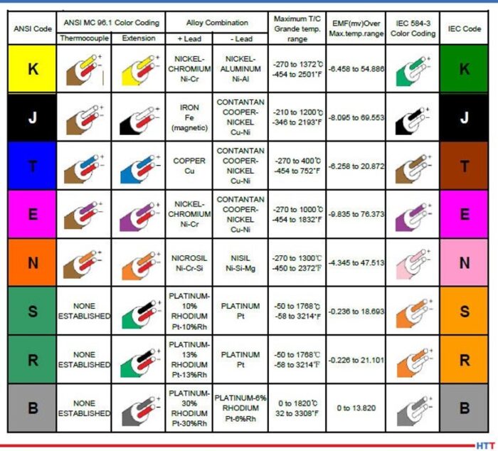
Introducing Your Common Thermocouple Types
What are the common thermocouple types?
Thermocouple material is available in types K, J, E, N, T, R, S, and B. These thermocouple types can be separated into two categories: Base and Noble Metals.
Types K, J, E, N, and T are Base Metals. They are made from common materials such as Nickel, Copper, Iron, Chromium, and Aluminum. Each base metal thermocouple has preferred usage conditions.
Types S, R, and B thermocouples are Noble Metals because they are made of one or more of the noble metals, such as Ruthenium, Rhodium, Palladium, Silver, Osmium, Iridium, Platinum, and Gold. Noble metals resist oxidation and corrosion in moist air. Noble metals are not easily attacked by acids. Some Noble metal thermocouples can be used as high as 3100°F.
(Pelican Wire)
Culprits of a Stable Thermocouple
Factors affecting the stability of a thermocouple:
The EMF output of any thermocouple will change slightly with time in service and at elevated temperatures. The rate and change are influenced by metallurgical and environmental factors. The four factors that can induce EMF drift are: Evaporation, Diffusion, Oxidation, and Contamination.
(Pelican Wire)
Does Length Matter?
Does the length of a thermocouple wire matter?
In a word, “Yes.” There are several factors when considering the maximum length of a thermocouple assembly. Total loop resistance and electrical noise. Total loop resistance should be kept under 100 ohms for any given thermocouple assembly. Remember, the total loop resistance would include any extension wire used to complete the circuit. Motors and power wires can create noise that could affect the EMF output.
(Pelican Wire)
Type N Thermocouple (Nicrosil/Nisil)
Type N Thermocouple (Nicrosil/Nisil): The Type N shares the same accuracy and temperature limits as the Type K. Type N is slightly more expensive and has better repeatability between 572°F to 932°F (300°C to 500°C) compared to type K.
(Pelican Wire)
Know Your Thermocouple Wire Insulations
Know your thermocouple wire insulations. When is Teflon® not Teflon®? Teflon® is a brand name for PTFE or Polytetrafluoroethylene owned by Chemours, a spin-off from Dupont. FEP is Fluorinated Ethylene Propylene. PFA is Perfluoroalkoxy Polymer. All three are part of the Fluoropolymer family but have different properties. Of the three compounds, PTFE has the highest heat resistance, PFA second highest and FEP third. The higher the heat resistance the more expensive the insulation. Keep that in mind when specifying the insulation and only pay for what you need.
(Pelican Wire)
Check out these magazines to see where these tips were first featured:
Heat TreatToday publisher Doug Glenn wraps up this three-part series with Pelican Wire experts by talking with John Niggle from Pelican Wire about thermocouple insulation types and considerations.
The first two episodes cover the history, types, vocabulary, standards, and other basics of understanding how thermocouples work. Listen to the previous episodes of the series here.
Below, you can either listen to the podcast by clicking on the audio play button, or you can read an edited transcript.
The following transcript has been edited for your reading enjoyment.
Doug Glenn (DG): Welcome to Heat TreatRadio!
John Niggle (JN): Yes, it's good to see you again, Doug. I know we've run into each other a couple of times out there in the field. I'm looking forward to having the opportunity to do all of this stuff in person again.
DG: It will be nice. Before we hit the record button, we were talking about shows this fall and hoping that they happen because you, like I, are ready to get out and go.
You are the business development manager for Pelican Wire. If you don't mind, give us just a little bit of background about you and about your experience in the whole thermocouple world.
Pelican Wire headquarters
JN: Sure, absolutely. As you said, I am the business development manager at Pelican Wire. I've been at Pelican since 2013 so we're working out my eighth year here. I'm a career industrial sales representative. I do have previous experience also, actually, in the process instrumentation industry. Way back when, before I even knew how to spell thermocouples, I was selling that stuff when I first got out of college. My career has, sort of, gone full circle, let's say.
DG: Very nice. Well, you've got plenty of years of experience, which is great. We've had two previous episodes with your colleague, Ed Valykeo, and we covered a good bit of stuff. We covered a lot of basics in the first episode. We covered standardization, and things of that sort, in the second episode. I want to encourage any listeners who haven't listened to those episodes, feel free to go back, Google “Heat TreatRadio” and search for “Pelican Wire” and listen to episodes 1 and 2.
John, you and I want to move forward. I'm always kind of curious about this question: From your perspective, with your experience, why do we use thermocouples? Let's talk about what they are and why we use them.
JN: First of all, we have to assume that somebody is trying to measure the temperature of some sort of a process- a process or an event of some kind. That's basically what they're trying to do. Compared to other devices like RTDs, bimetal thermometers, liquid expansion state change devices and so forth, thermocouples are robust, they're inexpensive; they're repeatability, they're ease of use and size -- all of those factors lead them to be more widely used than another sort of thermal measurement device of any kind. It is the preferred method.
On top of that, I mentioned the expense part. Because they're relatively inexpensive, there are certain industries, the heat treat industry and smelting industry, for example, consider these as, actually, consumable or disposable. So, the cost factors in significantly in the industry that we're talking about here.
DG: I live in western Pennsylvania and the town where my wife grew up, there was an old Leeds and Northrup manufacturing plant. I believe they made the consumable thermocouples for melt shops. You would, basically, throw the thermocouple in and it would melt quickly but it would give you a response during that time.
CLICK to Listen!
JN: Right. And, as I mentioned earlier, the response factor is important, or that's one of the factors considered, when people are looking at thermocouple wire. And, you're correct, Ed Valykeo, as you mentioned, has 40 years of experience in the industry and has seen exactly the same sort of thing that you're talking about where people will just tack weld it onto something that gets thrown into a furnace or it gets thrown into a melting pot or something like that, and they're looking for that instantaneous temperature.
If you don't mind, I'll tell you that we've done some work, actually, in the aerospace industry and we had a customer that we sold significant, literally miles, of thermocouple wire to (when I say aerospace, it was specifically for space exploration) and this was because of whatever we had done with the insulation. I can't tell you, because it was before my time, but this is what was relayed to me- they were able to get another 3 - 4 seconds of temperature measurement out of that wire. That critical, extra data for them made all the difference in the world.
DG: We're going to get to the insulation part which should be interesting. You won't have to tell us any trade secrets, but we are headed in that direction anyhow.
So, different types of thermocouples. Again, just a review question for us. Why use them? Why the different types and why are we using different types?
JN: Forgive me, Doug, and the rest of the audience, for that matter, if I end of repeating some of the things that came out in the previous episode. Basically, when you're talking about thermocouples, there are the two chemistries; for lack of a better term, you have “base” and “noble” metals. The base metals are really the metals that we focus on at Pelican. The noble metals are the more expensive ones- rare earth metals, tungsten, titanium, platinum and all those sorts of things that people spend exorbitant amounts of money on. There are purposes for those, but, typically, what you're going to see in the heat treat industry, in particular, you're going to see a lot of the base metals.
I like to say that, truly, the 20 gauge K, in particular, is the 800 pound gorilla in the room. It's almost considered, and I think it would be by people in the industry, a commodity. There are untold miles of that wire that are used in the heat treating and smelting industry. K is used, really, because of the temperature range. It fits in well with what people do in the heat treating industry. It is good for temperatures from zero up to around 1260 C. It's inexpensive, it covers the ranges that those people are looking for, and, again, it's the 800 pound gorilla in the room when it comes to temperature measurement in the heat treating industry.
Click to read the Heat Treat Today Original Content article on thermocouples.
The other types such as J comes up periodically, particularly if you're looking at lower temperature ranges. You won't see it quite as often in the heat treating industry. You will see it somewhat, but not to the degree that you would K. The J thermocouple wire has an iron leg so it does oxidize and you need to be careful about that sort of thing. Type T thermocouple wire has a narrower range. It has very good response times in cryogenic and cold temperature applications. The higher, upper end of type T thermocouple wire, typically, wouldn't be of terrible interest to the audience that we're involved with here, for the most part, because the upper ends around 370 to 400 C degrees, in lab environments; that's where it's going to be the most popular.
There is also type E. It's a higher temperature, as well. Response time. Broader range is a little bit better than K at lower temperature ranges. An interesting one is type N that you will see fairly often in the heat treating industry. For those people not familiar with type N, it is different alloys than type K. It covers virtually the same temperature range that type K does and will, actually, have less drift than type K. It is more expensive because of the alloys that it is made of, but, again, if you're interested in less drift, then type N is worth looking at. It hasn't quite caught on in the US the way it has in, say, Europe, in particular, and that really has to do with the infrastructure of the instrumentation. People have instrumentation that is either calibrated for K or J or something like that. Now, there is instrumentation out there, now, that would use K and N both, so we may see more, particularly, in the aerospace industry I would think it would become more and more popular.
DG: That's helpful. It's always good to hear those things over again.
How about the parameters and/or the factors that need to be considered when you're constructing the wire to start with? What do we need to be worried about in that area?
JN: I don't know if I like the word “worried” exactly, Doug. It's more, what do we need to think about? What do we need to be concerned about? Besides the metallurgy that we just talked about, we need to think in terms of what the sensor is actually going to look like. Is it just the wire? Thermocouple wire, by itself, can be a thermocouple; that's it, without any protection or anything like that.
As I mentioned earlier, you can tack weld it to an ingot, or something like that, and there you go. You don't have any probe, there is no thermal well to protect it or anything like that. But, what we do need to think about, then, is the process that it's going to be involved in. Where is it going to be used? Is it going to see an environment where there is a flow. Is it going to see an environment where somehow the thermocouple wire can become damaged? In that case, then, we're headed in the direction of talking about what our customers are interested in. And for a customer for Pelican Wire, we're mainly talking about people who actually assemble thermocouples – they make the connections, they have the molds and all that sort of thing.
To be clear, Pelican Wire just makes wire. And, again, the thermocouple wire can be used as a thermocouple, but a tremendous amount of wire is actually connected to some sort of a sensor or a probe, as I said, and is protected in a thermal well or something along those lines.
"But, what we do need to think about, then, is the process that it's going to be involved in. Where is it going to be used? Is it going to see an environment where there is a flow. Is it going to see an environment where somehow the thermocouple wire can become damaged? In that case, then, we're headed in the direction of talking about what our customers are interested in."
John Niggle
DG: Do we also have to be concerned with oxidizing, carburizing atmospheres, corrosive atmospheres? Is that, also, something that we need to be aware of?
JN: Absolutely. And that is one of the reasons you will see a probe thermocouple is because the wire is protected from that atmosphere. Nearly all of the wires that we talked about would be affected, particularly, in say, like a sulfurous environment; it would be subject to corrosion, oxidation and something along those lines.
Other factors, of course, are the accuracy and how much space we have. Believe it or not, if it's going to go into a small orifice, then we need to think about what the age size is going to look like. And then the environment: Is it going to be abrasive? Is there movement? Is there some sort of braiding motion that could wear a hole in the wire in the insulation and so forth? There are a lot of things to think about.
DG: And, it would probably be a good idea, especially if our heat treat people are running anything outside of the norm, regardless of what it is, whether it be atmosphere, configuration, fixturing, if there is anything outside the norm, they would probably be wise to mention it to the thermocouple wire and/or thermocouple probe manufacturer and make sure that they know so that you guys can get help get the right thing on there in their furnace.
JN: Yes, absolutely. At the end of the day, we work with this every day. We have design engineers on staff who can assist with technical questions and so forth and, of course, our customers, and the actual thermal wire assembly people, this is what they do every day of the week.
“I'll tell you that we've done some work, actually, in the aerospace industry and we had a customer that we sold significant, literally miles, of thermocouple wire to (when I say aerospace, it was specifically for space exploration) and this was because of whatever we had done with the insulation.”
DG: Let's talk about something a little bit new, I guess, to our conversation here in this 3-part series, and that is the insulation that's going to go around these wires. Can you tell us what are the different types of insulations and what are the advantages and/or disadvantages of each, and why would we be using them?
JN: I'll break it down into, what I would call, the four basic categories. That would be an extruded insulation, insulations that are tapes, fiberglass insulations that are routinely worked with and then, of course, high temp textiles. High temp textiles, in particular, would be of interest to the audience here in the heat treat metallurgy world.
Extruded insulations can be a variety of thermoplastics. A term that, I think, Ed has probably mentioned before and we've talked about before is extension grade wire. That typically has a PVC insulation on it and the reason PVC works for that is that it's cheap and extension grade wire, typically, does not see the sorts of high temp environments that you're going to see in processes. It's really a signal wire that takes the signal from the probe or from the sensor to the process control device.
DG: So what kind of temperature tolerances can the extruded wire handle? Are we talking 300, 400 degrees? I guess you talk C, I talk F.
Teflon frying pan
JN: We talk whatever language our customer likes to talk, but we do talk C quite a bit. So, PVC is quite low, it's in the 200s F. But, when you're looking at fluoropolymer insulations (and Pelican is really a high temp house, so we focus on the higher temp insulations) you have FEP and PFA, those are in the 200s. PFA actually goes up to 260. So, you can see, it's probably not suitable for heat treating applications, smelting and that sort of thing. The advantages to those compounds would be that you're going to have abrasion resistance. Think about your Teflon frying pan: it's slick, it's smooth. So, if you're in an environment where there is some movement, it will be good for that. And, of course, it will have excellent moisture resistance and chemical resistance. Those would be the advantages to the extruded wire. The other advantage would be, because you'll have a thinner wall than you will with the other insulations, you'll have some more flexibility. So, if you have a type N radius, you can go around a corner easily.
The next step up, in terms of temperature resistance, would be the tapes. Basically, in that area, you're looking at PTFE tape, mica take and capped-on tape or polyamide tape. Those will give you slightly higher heat resistances. The mica, in particular, would give you more. (Mica, as a matter of fact, is used as a supplement to the PTFE to give it even higher heat resistance.) Mica will go up to 500 C, PTFE and the polyamides match, in terms of heat resistance, the extruder products around 260. What they do give you, again if you use the tapes, is the heat resistance you're looking for, some abrasion resistance and the moisture resistance. You'll have less flexibility because those products are stiffer, but they're also going to be a little bit lighter weight unless you incorporate the mica into it. Then, when you do that, you're going to end up with an even stiffer wire and it will be a little bit heavier, and all those will be larger in diameter than an extruded wire. If you look at an environment where you need to poke the wire through a hole and that hole is an eighth of an inch, you need to think really hard if what you're doing is going to work.
DG: So you've got extruded and you've got tapes.
JN: The next step after that would be fiberglass. In the case of fiberglass, you have E glass and S glass. Of the two, E glass would have the lower temperature resistance and you're looking at 482 C on the high end. For S glass, you're up to 704 C. Now you're starting to talk about insulations that you will see in the heat treat environment; it's quite common, especially on the S glass side where you're looking at the 704, you'll see a lot of people that need 500 C for whatever reason. The advantage, obviously, to the glass, as I mentioned, is the higher heat resistance.
There are disadvantages. Think about fiberglass for a minute. We actually have to saturate the wire to keep it from fraying without it ever really experiencing any abuse. If we don't saturate it, then the wire can fray, and you can get fiberglass in your fingers even, which is unpleasant. So, fiberglass has some disadvantages like that. If you put it in an environment where there is some movement, abrasion, vibration or something like that, it can be problematic. Also, it's going to be stiffer because it's saturated, typically. Sometimes you'll even see those saturants even cause problems in a heat treat environment where, if it gets too hot, the saturant can leave an ash behind. You're going to lose flexibility, as I said. You're not going to have the abrasion resistance, the chemical resistance or the moisture resistance that you're going to get from an extruded product.
The other one that we see, again, literally miles and miles and miles of, in the heat treat world would be what's called Refrosil and Nextel, (those are both, actually, trade names). We're talking about vitreous silica and ceramic. Again, those are, what we call, high temp textiles. Now, you're looking at products that are in the 1200 C range. Ceramic goes up to 1204, vitreous silica is in the 870's. Again, there are some of the same disadvantages with those that you're going to have with glass. It's going to be somewhat fragile. We don't saturate those because the saturants are not going to hold up in the environments that they're going to be placed into, so you would have that ash residue left.
Again, it will be stiff, it will be even larger in diameter than the fiberglass, which is larger than tape which is larger than the extruder products. Of course, you're not going to have the abrasion resistance, the moisture resistance or the chemical resistance. But it does protect the wire in those elevated temperature environments that are critical for the heat treating industry.
DG: Let's back up a bit. I want to understand something you said. You said, in the fiberglass, it is saturated and in the textiles it's not. I want to know what you mean by saturated.
JN: It's either a solvent-based or a water-based saturant that is applied to the wire to protect it. Think in terms of a varnish. It would be like a protective coating. Again, it just keeps the exterior of the wire, the bare wire, from being exposed. It's a coating, but we call it a saturant.
DG: High temperature textiles tend to be the stuff we're using, in the heat treat industry, probably most.
JN: Yes. Again, when I mentioned the 800 pound gorilla in the room, the 20-gauge K with the vitreous silica or the Refrosil would be an extremely popular product in the heat treating industry, absolutely.
DG: Let me ask you a very, very fundamental question. I'm curious of your answer to this. Why do we insulate wires at all? Is it done to protect from temperature or is it done simply to protect them from crossing with each other and grounding or shorting out? Why do we insulate?
"I'll go back to something that I know Ed talked about: the Seebeck effect. You have this loop; if you don't have that loop, then you don't have anything. You don't have the EMF, the electromotive force, that you're looking for."
John Niggle
JN: It is the second part. When you look at any wire construction, the two singles have to be insulated from each other. I'll go back to something that I know Ed talked about: the Seebeck effect. You have this loop; if you don't have that loop, then you don't have anything. You don't have the EMF, the electromotive force, that you're looking for. We do make a wire that is not duplex, but, typically, what you're going to see is a wire that has two singles and then it's duplexed with an insulation over the top. We do make a wire that the two singles are jacketed in parallel and then no jacket is placed over the top but that is for an application that wouldn't be suitable for the heat treat industry.
DG: I asked that question, because for those who are unbaptized in this conversation, it's kind of interesting. So, we're talking about insulation and we're doing a lot of conversation about temperature ranges and, for someone who wouldn't think so, they would say, "Well, that means you're insulating because of temperature." But, really, the reason you're insulating wire is for electrical. It's to keep them apart. It's just how high of temperatures those insulations can handle, not that you're insulating the wire to keep them cool. Right?
JN: Absolutely not.
DG: That may sound very basic, but there may be people that think that, so I want to get that on the table.
JN: Most of the people in the audience are probably familiar with this already. Typically, what happens is the wire is stripped so we have exposed ends. And then those ends, as we mentioned earlier, can be tack welded onto something or they can just be out there. The thermocouple world, by the way, is an incestuous world where we have customers, we kind of compete with those customers, some of our customers compete with others of our customers but then they buy supplies from each other. You probably already know that from talking with other people in this industry. At any rate, the wire is stripped and then it's either tack welded or it's connected to some sort of sensor or probe of some kind.
DG: It's a tangled web, the whole thermocouple world. You've got customers, yet you sell to certain suppliers who also sell to those customers. It can be complicated! But that's OK, we'll let you guys worry about that; we just want to make sure the thermocouples are good and we'll be in good shape.
Another question for you: We talked about the process and a lot of different environments about what type of thermocouple you should use, but does the process being monitored influence the type of insulation that should be used? Obviously, temperature is going to have an impact, but is there anything else?
JN: Yes. Let's circle back to what we talked about earlier just a little bit. When you look at the process, you need to think of what is going to happen to that wire? Is it going to see, first of all as you mentioned, the temperatures? That is certainly important so that comes into play with the insulation. But, we need to think about, Is there movement? Is there going to be some abrasion? Is there some sort of activity that could damage the wire somehow? Then, we need to look at the chemicals, like we talked about. Do we need some chemical resistance? Do we need water resistance? Is it going to be submersed in something? Those things all need to be considered.
Again, as I mentioned earlier, the actual placement of the wire. Does it need to be inserted in a hole? At Pelican, we produce wire down to 40 and actually 44 gauge which, I think, will probably be stunning to most of the people in your audience because, again, 20-gauge K is what these people think about. In the heat treating industry, what you see is they need a robust wire, something that's going to be able to handle those temperatures and a large conductor like that.
Another thing to think about, actually, is a bend radius. Are you going to put the wire somewhere where it needs to go around a corner, around a bend? Then, are you better off using a stranded wire? A stranded wire is going to have more flexibility. You can buy a 20-gauge stranded wire, you can buy 24-gauge, 28-gauge, 36-gauge.
DG: Now, what do you mean by stranded?
JN: Stranded wire would be instead of just one solid 20-gauge conductor, you have multiple strands that make up that 20-gauge. But, if you think about it, multiple strands of wire will actually be more flexible. You'll still get the same results, but it will be more flexible if you need to go around a corner or if you need to insert it into something.
DG: It's almost like a braided wire as opposed to a solid.
JN: Yes. Now braiding is a little bit of a different process. When we're talking about stranded wire, it's, basically, just spiral. Braided is more crossed into each other, which, coincidentally, is the way that the fiberglass and the high temp textile insulations are made – those are actually braided. And, by the way, I'll just toss this out, it's made on equipment that really hasn't changed since the ‘20s. I'm not talking about the 2020s, I'm talking about the 1920s! Rumor has it, some of that braiding equipment was, actually, designed by Thomas Edison. I'm not sure if that's really true. But that is the process used to apply the fiberglass and high temp textiles.
DG: So, anything else as far as any other considerations we need to take into consideration when we're talking about choosing insulation? If not, that's fine.
JN: I think I covered them, Doug.
DG: At Pelican Wire, your company, I know you guys deal with a broad number of markets, I'm sure, one of them being heat treat. What do you see as any special demands or special concerns that are, maybe, unique or, at least, inherent in the heat treat market?
". . . what you see is insulations that are higher in temperature resistance, as well. In some cases, as I mentioned earlier, in ovens where there is a saturant involved, we could see ash. Some people ask that saturant not be applied to the fiberglass and that's certainly something that can be done."
John Niggle
JN: For the heat treat market, again, I'll go back to what I said earlier, we see a lot of 20-gauge K used. It's because of the higher heat requirements, the higher heat that is involved with the processes of heat treating. Secondly, what you see is insulations that are higher in temperature resistance, as well. In some cases, as I mentioned earlier, in ovens where there is a saturant involved, we could see ash. Some people ask that saturant not be applied to the fiberglass and that's certainly something that can be done.
Sometimes we're even asked to not put tracers. We go back to what we talked about earlier with the metallurgy- you have two legs, a positive and a negative leg. Well, how do those end users tell those legs apart if they look similar, if they're an alloy of some kind? So, we put a tracer wire in there so you have a red leg and a yellow leg, in the case of type K, or sometimes you just have a red leg depending on what they ask for. Those tracers can, actually, cause problems, too, if the ovens are hot enough and they are in there for long enough times. We even have customers who ask us not to put tracers in their wire, for that matter.
Accuracy, of course, is extremely important. I know that Ed, in a previous episode, talked about standard limits, special limits and all that sort of thing. Typically, you're going to see special limits used in the heat treat industry and, in some cases, we're asked even for special calibration points. In previous podcasts, I've heard you talk with other people about AMS2750 and how that comes into play. It is extremely critical for the folks in the heat treating industry and something that clearly a thermocouple wire producer has to understand.
Episode 1 of 3 of AMS2750 series
DG: Let's say you've got a customer that calls you and wants to talk about their thermocouple needs, let's say there is some sort of special need. What would you suggest they have, in hand, when they call you? What do you need to know from them to help you do a better job with their thermocouple needs?
JN: Honestly, the first question we do ask is: What temperature are you going to be running this at? How hot are we going to be? We, absolutely, need to know that. That helps us narrow down the alloy that we might be looking at, whether it's type K, type J, type E, or whatever. And then, of course, it's a natural thing to dial in the insulation after that. Quite honestly, one of the things that frustrates me is when people say, "I need Teflon." Well, OK. Do you need FEP or do you need PFA? Those are both fluoropolymers like Teflon is. We need to talk about temperature resistance, so don't tell me you just need Teflon. We do need some specifics when it comes to that sort of thing. Again, we talked earlier about stranding and stranded wire. Do you need some flexibility? What gauge size do you think you need? How robust does this wire need to be? Those are some of the key factors we need to know about.
DG: Let's say, for example, somebody does want to get a hold of you or Ed, your colleague who was on the first two episodes, how is best to do that? How can we get a hold of Pelican Wire?
JN: Our web address is www.pelicanwire.com, about a simple as it possibly gets. Our email addresses are, actually, quite simple, as well. If anybody wants to email me, it's jniggle@pelicanwire.com. You can contact me directly, if you want to, or we have a sales inbox and that is simply sales@pelicanwire.com. We do have a phone number, but it seems a lot of people don't care about phone numbers as much these days. But the number is 239-597-8555.
DG: I have one, unrelated, question for you that I know the world is wanting to know: How is it having a company in Naples, Florida, that's what I want to know?
JN: I'll tell you what, Doug, the answer today will be different than the answer in October or December. It's actually quite nice. We moved down here 8 years ago in 2013. I moved from the Midwest and didn't really feature myself owning palm trees, but I own palm trees, which is pretty darn cool. We are, as the crow flies, about 3 miles from the water, where I live anyhow, 20 minutes by car. Our office and manufacturing facility are, actually, on the very edge of the everglades. You can see the picture in the background behind me. That's our building. That's actually facing east. That is a sunrise over the everglades. We're on the very edge of the everglades. There is a lake right next to our building and then, after that, it's everglades all the way over to Miami. And, real quick, our weather pattern comes from the east. It doesn't come from the Gulf. This time of year, in the summer at about 3:00 in the afternoon, about the time that we're doing this call right now, a thunderstorm blows up and it comes from the east over the everglades and it moves to the west. The trees blow that direction, you can see it coming. It's interesting. During the wintertime, I have to tell everyone, you'd probably be jealous, but it is truly paradise.
DG: Yes! I've been to Naples, ate at a nice restaurant down there, years ago, but it was very nice.
You guys are also employee-owned, right?
JN: That's correct, yes. The company is over 50 years old. The founder of the company passed away in 2008 and, before he passed away, he converted the company to an employee-owned operation. So, we've been employee-owned since 2008. We've purchased a couple other companies since then that folded into, what we call, the Wire Experts Group. Pelican Wire is part of that. We have a sister company out in Colorado. We bought another facility in Chicago and folded that into our company in Colorado. So, yes, we're employee-owned and it works out really well for the employee owners, I'll tell you that much.
DG: That's great. John, it's been a pleasure talking with you. Thanks for taking the time. I appreciate your expertise. Hopefully, we will see you out on the pavement somewhere in the real world.
JN: I'll, actually, be seeing you at the heat treat show in about 3 weeks.
DG: That's about right, yes.
JN: Hopefully, some of the people that are listening we will see, as well.
Doug Glenn
Publisher Heat TreatToday
To find other Heat Treat Radio episodes, go to www.heattreattoday.com/radio and look in the list of Heat Treat Radio episodes listed.
Heat TreatToday publisher Doug Glenn has a second conversation with long-time thermocouple industry expert Ed Valykeo from Pelican Wire about T/C accuracy and classifications. Listen to learn more.
This is the second episode in a series of three on Thermocouples 101. Check out the first episode of the series here.
Below, you can either listen to the podcast by clicking on the audio play button, or you can read an edited transcript.
The following transcript has been edited for your reading enjoyment.
Doug Glenn (DG): Ed, welcome back. I'm glad you were brave enough to come back. Last time, Ed, we talked about a lot of good basic thermocouple stuff. We talked about, basically, Thermocouples101 which I mentioned last time, was one of the best and most well read articles on our website, which is great. We covered a lot of different things last time. I was just reviewing it, and it's interesting, we were talking about several different men as you gave a good history of thermocouples starting back in the early 1800's and talking about guys like Alessandro Volta, where we get the word volt, and Thomas [Johann] Seebeck and the Seebeck effect or the Seebeck coefficient, and things of that sort. We talked about all the different noble thermocouples, J, K, E, N, and T, and we talked about the N leg and the P leg on all of those which was all good. It was very interesting. If you didn't listen to the first episode, you ought to go back and listen to it. It's really a pretty good summary of thermocouples, a basic primer on thermocouples. We also did some things like vocabulary for ourselves; we learned what an EMF was, electromotive force and things of that sort. It was very good.
This time, I think we want to move on to, what we could commonly classify or in a big picture classify as, standardization and accuracy discussion. But, before we do, I've got a quick follow-up question from the last episode. We had mentioned that an EMF is produced when two dissimilar metals are joined together or placed together. There is a very, very, small electric current that's created. My question is: Can you do that with any metal? Is it possible? Or do you have to have only certain types?
Ed Valykeo (EV): Theoretically, yes, you could probably join any two different metals and produce some sort of voltage. However, the accuracy of that, and if doesn't mean anything, probably not. The thermocouple base metal thermocouples that we talked about last time, are industry known, used worldwide and, quite honestly, have been perfected over many, many years. So, yes, you could generate a volt probably from any two metals, but, really, to produce an accurate thermocouple, something you can measure temperature with, you're going to want to stick to the thermocouple types that we talked about.
And again, today, we're talking about the base metal thermocouples which are known as Type K, Type J, Type T, Type E and Type N. Those are the base metal thermocouples.
DG: Let's talk a little bit about standardization of these things, and accuracy. My understanding, Ed, is that there are one or more organizations out there in the world that deal with certifying, qualifying, or giving us standards for these thermocouples. Can you tell us a little bit about those organizations? Then, we'll jump in and talk more specifically about the classifications and accuracy.
EV: Sure. One of the bodies that we use is ASTM. In ASTM-E230, are all the thermocouple tables for the different types of thermocouples, not just the base metal, but also noble metal. It's a fairly lengthy book. All the thermocouples are based on the ITS-90 scale and that is the EMF output of each one of these thermocouples at prescribed temperatures. We could go into more detail with that if you'd like, but there are a number of ways that they have extremely accurate temperature medium to measure the thermocouple output. But, that's what the tables in ASTM-E230 are based on, the ITS-90 scale.
When we talk about ASTM, there are also a couple of other standards that we use, and we'll probably get into a little bit later in the conversation when we talk about calibrating the thermocouples themselves. So ASTM-E220 and ASTM-E207 are the two that are used in calibration of the thermocouples.
DG: But, basically, the organization that does that, I don't know if we want to call them a lab or not, but the organization that does is it ASTM.
EV: ASTM is one of the bodies that publishes the books that I call the standards for thermocouples. I think I won't be mistaken, but ITS-90 is really more an IST list. They control the ITS-90.
DG: Let's move into the accuracy standards, then. I think you mentioned the ASTM-E230. Is there anything else we need to talk about as far as the accuracy standards, or did we already hit it?
EV: Certainly, in the ASTM-E230, they spell out the different types of thermocouples, as I mentioned, the base metal thermocouples, but the accuracy of each one of those is listed in the ASTM-E230.
DG: What about classification? Let's talk about the guidelines for classifying these different thermocouples.
EV: Again, ASTM-E230, and there are other publications, but, again, we use ASTM here. The classification of the thermocouples are also spelled out in ASTM-E230 and basically, we talk about special limits of error, standard limits of error and extension grade thermocouple. Again, those can be found in E230.
DG: So, when we classify those, are we classifying them based on temperature deviations or the temperature tolerances? Is that, basically, what it is?
EV: Yes. It's based on temperature tolerance. I'd like to share a quick rule of thumb for classification of those thermocouples. So, special limits of error, basically from zero degrees Fahrenheit to 500 degrees Fahrenheit, it's + or - 2 degrees, and above 500 degrees it is + or - .4%. For example, at 1000 degrees, you're looking at + or - 4 degrees; if you have 2000 degrees Fahrenheit, the tolerance at 2000 would be + or - 8 degrees for special limits of error.
On the other side of that, you've got standard limits of error, and, basically, you could just double that. From zero to 500 degrees Fahrenheit, you're talking + or - 4 degrees; at 1000 degrees would be + or - 8 degrees and at 2000 degrees, + or -16 degrees.
Where there is some confusion, and maybe some people don't understand thermocouples, is when we talk about extension grade. There are actually two types of extension grade. There are standard limits of error and special limits of error extension grade. Extension grade is just exactly as it sounds. It carries that signal from your sensor all the way back to instrumentation rather than run maybe a little more expensive wire all the back to your instrumentation, you're going to put extension grade to continue that circuit back to the instrumentation. Extension grade is the same metals as the thermocouples. If you're using Type K sensor, then you're going to want to use Type K extension grade, and so on, for the rest of the base metal thermocouples. The difference is that the extension grade material is only guaranteed to meet the tolerances up to 400 degrees Fahrenheit. If you look at ASTM-E230, the tolerances only go, on extension grade, to 400 degree Fahrenheit. And, actually, Type T is a little bit different; Type T only goes to 200.
DG: In the heat treat industry, that's not really going to do us much good, right? I mean, most of our processes are well above 400.
EV: It is. That's why you would never use an extension grade as the actual sensor. This is some of the confusion out in the industry: “Well, I can just take my extension grade, create a junction and use it to measure temperature.” You probably could up to 400 degrees, but it's not guaranteed above that temperature, and you could get yourself in trouble.
DG: So, you run extension grade outside of the furnace because, obviously, you're not above 400, so you can use extension grade to run it. I think last time we talked about no more than 100 feet rule of thumb.
Extension grade is basically this: Here's your extension cord that you can run from your regular wire, either your standard limit of error or special limit of error, from that to the box.
EV: Exactly. And so, the key to understanding extension grade is the tolerances on that extension grade are the same – say if you have special limits extension grade – it's the same as your special limits thermocouple wire, + or - 2 degrees, in this case, up to 400. It's guaranteed to meet special limits of error and then the same thing on the standard limit side. You just double those tolerances. Again, it's really the temperature that it is guaranteed to.
DG: Very good. So those are the different classifications. We've got special limits of error, which is a tighter temperature tolerance, and then we've got standard limits of error, which is a little less tight, and they we've got our extension grade which is only classified up to 400 degrees anyhow.
I know some heat treat processes require very, very tight temperature tolerances, especially in things like aluminum brazing and things of that sort. Is it possible to get anything better than special limits of error?
EV: It is. The first thing I want to say is that they're not really recognized within ASTM, these tighter tolerances. But, in the industry, certainly in heat treating and in the pharmaceutical side where they typically use Type T, we've had many requests for tighter tolerance material. Some people call it quarter limit material or half limit material, there's a bunch of different names that it goes by. So, we go to our manufacturer's of the wire and request that and, most of the times, it's a no quote. It really comes down to more of a selection process.
For us here at Pelican Wire, we have a pretty good sized stocking program of bare conductor and sometimes what we can do is mix and match to try and meet the tighter tolerance material. There are a number of ways that some of the manufacturers, in fact, the heat treaters, will request special limits materials, that must meet + or - 2 degrees up to 1000 degrees and then .2% after that. It can be done and we do it on occasion.
DG: Let's follow up on that a little bit. How do you determine the accuracy of a lot of wire, or a spool of wire? How do you go about doing that?
EV: Let me back up just a little bit and start with the actual wire producer themselves: There are not any left in the States, so, basically, all the thermocouple wires are melted overseas, whether it be Germany, France, Sweden. When they melt, they try to meet special limits of error. Now you're talking each leg has to be melted separately; they don't melt them all at one time, right? So, each “melt” or “heat”, they are shooting to make special limits of error.
This is where some of the testing specifications come into play. ASTME-207 is a test method for single thermal element thermocouple wire. I don't want to confuse our listeners, but, again, if you think about a melter that just melted or heated a melt of wire and they process it down to wire, they only have one conductor. They want to know if that one conductor is going to potentially meet special limits of error. There is a testing specification that ASTM has (ASTME-207) that you can test a single leg thermocouple wire to see if it's going to meet special limits of error. What they do is they calibrate the single leg, they get their values (the EMF output), and they have the second other leg and they do the same thing. They, then, mathematically add the EMF of those two and go back and look at the standards to see if it's going to fall within the special limits of error.
That's how the melters, the folks that are melting the individual thermocouple legs, are doing it. We users, we are an insulator wire, we put the two legs together and now we have a thermocouple. The way we test those thermocouples is by using an ASTME-220, which is a comparison method. We're taking a known standard and we're calibrating the thermocouple wire against that standard and getting the temperature deviation from that. That's how we verify that the wire is meeting the tolerance that is requested by our customers, whether it's special limits of error, standard limits of error or even extension grade.
DG: When you say "a standard", what does that test actually look like? Are you taking a thermocouple that you know is good, sticking it in a hot furnace and your test thermocouple or are you just doing it through current testing or something like that?
EV: Good question. We actually use SPRTs (resistance thermocouples) high accuracy, that we use as our standard. They're calibrated at an outside firm, so we know what the output of that resistance thermometer is, and we calibrate our sample against that. The three things you need to do a temperature calibration is the temperature medium, the reference thermometer and the equipment to capture that output or measure the voltage that's being produced. Having those, we have our reference standard that we know the EMF or the temperature output of. Now, we put our thermocouple in the furnace and we compare the two. That's how you get your deviation.
DG: There are labs, I understand, that do these certifications and things of that sort, that certify the accuracy of the thermocouple. Now, Pelican Wire does that. You do have a lab and you do certifications, right?
EV: We do. We calibrate the thermocouples and we produce a test report showing the deviation of the thermocouple for the customer.
DG: Earlier, we were talking about standards and how there's the organization ASTM. How about for these labs? Do the labs have to meet some sort of outside third party certification?
EV: There is nothing that they have to do. I will say that there are a number of standards. We're ISO9001, but we're also seeking accreditation for 17025 so that our lab is accredited to IECISO17025, which just proves that we are a quality lab. We have our quality systems in place. We have our uncertainty budgets for all the equipment we use. A customer can feel confident that the calibration report that we provide is as accurate as possible.
DG: I think covers most of the things we wanted to cover in this episode. We talked about the standardization, the special limits of error, the standard limits of error, who are the bodies out there that do the certifications/classifications, if you will. I think we covered a good bit.
I think we were going to do one more episode, Ed, and I think we're going to talk about insulating materials. I understand that one of your colleagues is going to be there to talk about that with us, John Niggle.
EV: Yes. John Niggle will join the next podcast and talk a little bit about how now that we have the thermocouple wire, what kind of insulations do we put on that wire. It depends on the medium that it's going to be used in, the heat treater or whoever.
Doug Glenn
Publisher Heat TreatToday
To find other Heat Treat Radio episodes, go to www.heattreattoday.com/radio and look in the list of Heat Treat Radio episodes listed.


 Learn more about thermocouples in the interview between Doug Glenn and Eric Yeager on page 16 or check out the reference list below.
 Find heat treating products and services when you search on Heat Treat Buyers Guide.com

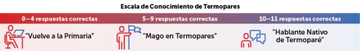
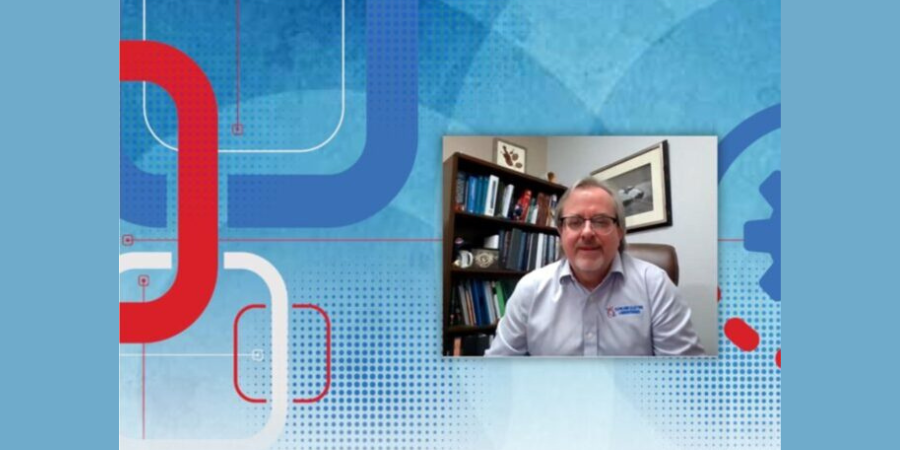
 What is a thermocouple?
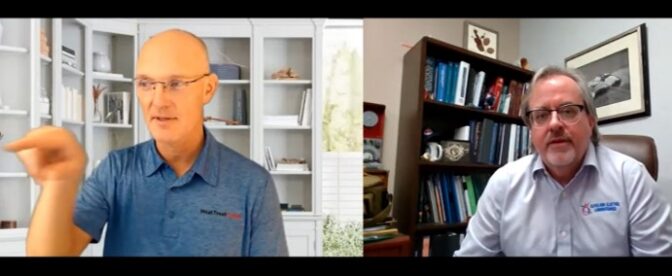 DG: Right. That’s interesting you say that, and it’s actually good that you say that, because some of our residential consumer thermometers (which a thermocouple is kind of like a thermometer in one sense) do have hazardous materials like mercury.