Safeguarding Refractory Installation: 12 Vital Steps to a Flawless Dry-Out

Installing new refractory materials is a necessary furnace maintenance practice which needs to be done periodically. But extended downtime and installation errors can be a major financial and operational headache. In this article, Dan Szynal, VP of Engineering & Technical Services, Plibrico, gives 12 factors which will ensure that the refractory installation is successful.
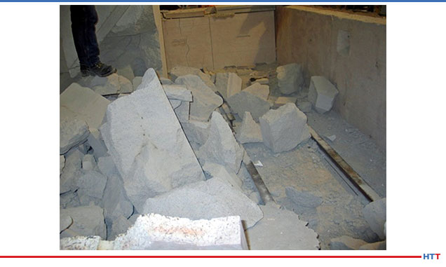
During an initial dry-out, the powerful effects of superheated steam can cause explosive, devastating consequences to freshly cured refractory material. To that end, removing moisture from castable and precast shapes is a serious pursuit. The production pressures to minimize downtime can lead to shortcuts and rushed dry-out procedures. Usually, these sidesteps have the opposite effect, quickly compounding delays and costs by causing thermal damage to the linings and potentially incurring personal injury.
Dry-outs fail due to imprecise management of water extraction from refractories. At the boiling point of water, the pressure of steam is less than 1 psi. However, at 700°F, saturated steam reaches 3,000 psi, and possesses enough energy to disintegrate the most resilient refractories. Too much heat, rapid ramp-ups, vapor lock, poor curing, and surplus water can contribute to potentially hazardous situations.
Here are the 12 preventive factors to manage for dry-out safety and success:
1. Hot spots and flame impingement. Ensure that your burner flame is centered accurately. The direction of flame in the vessel must promote equal heating of all the refractory surfaces. A flame that impinges on a single area of the surface will quickly create a hot spot, forcing an unequal expansion of water vapor in that area and resulting in thermal spalling.

2. Temperature spikes. Insulation is ill-advised. Attempting to cover green castable with an insulating blanket can lead to destructive temperature spiking when the blanket is removed, breaks, or falls off. At a wall surface temperature of only 550°F, the removal of insulation exposes the surface to an extreme temperature shift which will activate unequal steam expansion and pressure.
3. Thermocouple placement and monitoring. Pay attention to the locations and readings of your TCs. Watching only the coldest location will allow the hottest area of your vessel to heat too quickly in the dry-out schedule. Conversely, monitoring only the hottest area will allow the colder area to retain more water than specified. This will lead to failure later in the schedule or during hold periods. At 700°F, steam can exert 3,000 psi pressure.
4. Air temperature vs. surface temperature. Thermocouples should report surface temperature. Air temperatures are typically 50°F to 100°F hotter, thus misreporting schedule impact. The initial hold period is typically designed to melt burn-out fibers. That creates important permeability. If the actual load temperature is lower than specified, permeability is not created, leading to failure in the next ramp-up period.
5. Field vs. precast dry-out schedule. A field dry-out schedule is specified for single-sided heating. It precipitates a dual water migration, first (stage 1) towards the heat as the path of least resistance, but then reversing course (stage 2) and moving away from the heat, escaping towards the furnace shell. Field dry-outs are faster schedules than precast, where the pieces are heated from all sides simultaneously. The precast water migrates to the center of the piece, and that takes longer to escape. By misapplying the faster field dry-out to precast, there is a greater risk of water retention, which will ultimately lead to spalling, even at temperatures of 550°F or less.
6. Venting and air circulation. Proper venting is required to rid the furnace of water vapor during dry-out. Without vents and free air circulation, the steam is forced to exit via the furnace shell, which takes longer than the schedule would provide. Water will be retained closer to the shell side, increasing the likelihood for disintegration as temperature and steam pressure rise.
7. Surface coating. An impermeable coating on the refractory surface will prevent the stage 1 escape of water. Slowly, this water will be forced to move to its second exit, the furnace shell. This delay prepares the still-saturated refractory for failure at the next heat ramp-up.
8. Clear obstruction from weep holes. As stage 2 water migration occurs, it will escape to the furnace shell. There should be adequate weep hole capacity, cleared of obstructions which will allow the water to exit the furnace shell. These provide a release valve for buildup of steam pressure. Thermocouples need to be monitored at both hot and cold areas to measure temperature consistency. Pre-cast refractory requires longer bake-out schedules to release all water vapor.
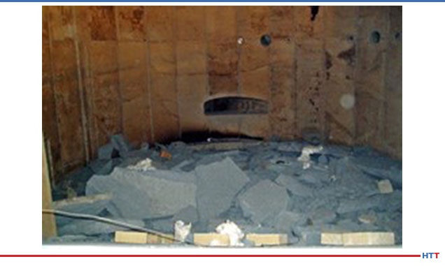
9. Cold weather curing. In the curing process, simple hydrates form needle-like morphology. These structures promote permeability, and water/steam can more easily migrate through the refractory to escape. Curing in below-freezing temperatures alters the hydrates to be less permeable, thus trapping the water, even during dry-out and creating an inherent risk. As well, cold weather curing slows the required strengthening process, leading to a weaker refractory and likely spall. We have had a thermal operator tell us about a below-freezing cure that went badly: The water in the castable actually froze in place. When the dry-out was initiated, the castable melted and fell to the floor, where it subsequently cured and dried.
10. Cutting short cure time. Recommended dry-out schedules always assume a 24-hour equivalent curing time at moderate temperatures. By cutting short the cure time, water is retained, and strength is reduced. For example, a conventional castable requires 24 hours cure time; high cement/low moisture castable needs at least 16 hours. Adherence to product cure time specifications ensures optimum strength and a successful dry-out.
11. Free water removal without consideration. The goal of curing and dry-out is to create permeability in the refractory at lower temperatures (300°F) to enable water to escape. By quickly ramping up dry-out temperatures for the sake of time, permeability is diminished. At higher temperatures, (+500°F) steam pressure rises aggressively. Again, refractory composition drives curing and dry-out schedules, and as a rule, the faster temperatures rise beyond specification, the higher the risk of failure.

12. Refractory strength as a function of water content. A simple 1% excess of water will reduce refractory strength by as much as 20%. Overwatering by 1.5% cuts strength 25% to 40%. The implications are profound: the refractory will not withstand the steam pressures in dry-out, and worse yet, there is more water that must be extracted. A successful dry-out can be jeopardized by the slightest variance in water composition.
Conclusion
Meticulous care in refractory installation is the foundation to successful furnace operation. While no one looks forward to non-productive downtime, close adherence to product specifications, cure times, and dry-out schedules will ensure a more profitable return to operations. Managing the water issues in refractory composition is job one.
Safeguarding Refractory Installation: 12 Vital Steps to a Flawless Dry-Out Read More »