CQI-9 Rev. 4 on Heat Treat Radio: What Will You Learn from the Experts?
![]() Heat Treat Today provides many different ways for you to keep current on heat treating technical content, news, trends, and specifications within the industry. Heat Treat Radio is one of those outlets. Publisher and Heat Treat Radio host, Doug Glenn, talked with James Hawthorne from Acument Global Technologies and Justin Rydzewski of Controls Service Inc., both of whom served on the committee, with Hawthorne being the chairman, of the latest revisions (Rev. 4) to CQI-9.
Heat Treat Today provides many different ways for you to keep current on heat treating technical content, news, trends, and specifications within the industry. Heat Treat Radio is one of those outlets. Publisher and Heat Treat Radio host, Doug Glenn, talked with James Hawthorne from Acument Global Technologies and Justin Rydzewski of Controls Service Inc., both of whom served on the committee, with Hawthorne being the chairman, of the latest revisions (Rev. 4) to CQI-9.
This column appeared in Heat Treat Today's August 2021 Automotive print edition.
Check out this article for a summary of the topics and insights discussed during this four-part series, and then listen to the individual episodes to learn all you need to know about understanding and complying with CQI-9 Rev. 4.
Heat Treat Radio:
Justin Rydzewski on CQI-9 Rev. 4
(Part 1 of 4) – Pyrometry
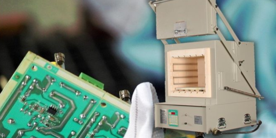
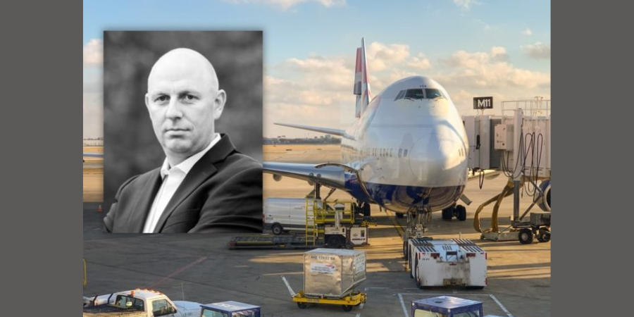
In this first episode, Doug Glenn and Justin Rydzewski provide an overview of CQI-9 and the “why” behind the new revision as well as talking down through the pyrometry section which covers things like sensors, thermocouples, calibration, SATs, and TUS. Rydzewski was an active participant in the writing of the new revision. His company, Controls Service Inc., is an ISO/IEC 17025 accredited provider of process control systems, calibration, maintenance, and services.
Here’s an excerpt taken from the transcript of the first podcast:
Doug Glenn (DG): Give us information about CQI-9. Give us a brief history. When did it start? Who owns it? Who maintains its updates? To whom does it apply? What is its scope?
Justin Rydzewski (JR): The best way I know to describe it (because, perhaps the most widely known pyrometry specification is AMS2750) is CQI-9 is the automotive equivalent of AMS2750. There are obviously some differences between the two documents, but, in a nutshell, that’s the comparison. It is a document supported by the AIAG, the Automotive Industry Action Group. They oversee the publication of it, the drafting of it, and supervise the whole thing through that process. CQI-9 is the number. Officially, it’s called the Special Process Heat Treat System Assessment and that kind of gets the nomenclature of CQI-9 that applies to automotive heat treaters, or any performing heat treat work within the automotive industry; and several processes fall into that category. It can be from commercial heat treat to in-house heat treat, to organizations like mine that support it. It applies to anyone participating in that effort of heat treat.
DG: Let’s talk about Rev. 4. You said as soon as “3” was out, you started on “4” and it took eight to nine years to get done with “4.” What was the main reason why you needed to abandon “3”?
JR: They schedule these things out to be rewritten on a routine basis. Like most specifications, they are reviewed on some established interval of time. The biggest difference between the second edition of CQI-9 and the third edition was that the third edition removed all references to AMS2750. When 2750 was in the document, it created a world of confusion, and the guidance and errata sheets that followed were just so numerous that they made it a somewhat difficult document to adhere to.
One of the ideas we brought to the table was that maybe we should just remove all reference to it [2750] and write our own specification. So, the third edition removed the 2750 references. In doing so, it ended up being a very well written document. It was effective. The OEMs—your GMs, Fords, FCAs—were happy with the results of the document.
 The prolonged active interval of that document allowed us to collect a lot of really good data about what was working, what wasn’t, what was confusing, and where additional clarity was needed. The more data we collected, the more confident we were that the fourth edition would truly make a stride toward being a more effective document.
DG: What are the major sections?
JR: It is structured very similar to the way of AMS2750 in that regard. You have four sections that divvy up a pyrometry section: thermocouples, instrumentation, system accuracy testing, and temperature uniformity survey. But, unlike AMS2750, CQI-9 is a system assessment, it is a process, it is a heat treat management system. It encompasses more than just pyrometry. Where AMS2750 is a pyrometry specification, CQI-9 is a process specification; it encompasses everything. It also includes your heat treat system assessment, which is three sections of questions regarding your heat treat operation, then you have your pyrometry which is those four sections I mentioned. Then you have your process tables. Your process tables drive all of your requirements for your particular operation, in terms of frequencies and tolerances.
To listen or read more about the CQI-9 pyrometry section, go to www.heattreattoday.com and search “Heat Treat Radio CQI-9”
Heat Treat Radio:
James Hawthorne and Justin Rydzewski on CQI-9 Rev. 4
(Part 2 of 4) – HTSAs & Job Audits
In this second installment, Doug Glenn, Justin Rydzewski, and James Hawthorne of Acument Global Technologies discuss heat treat system assessments and job audits in CQI-9 Rev. 4.
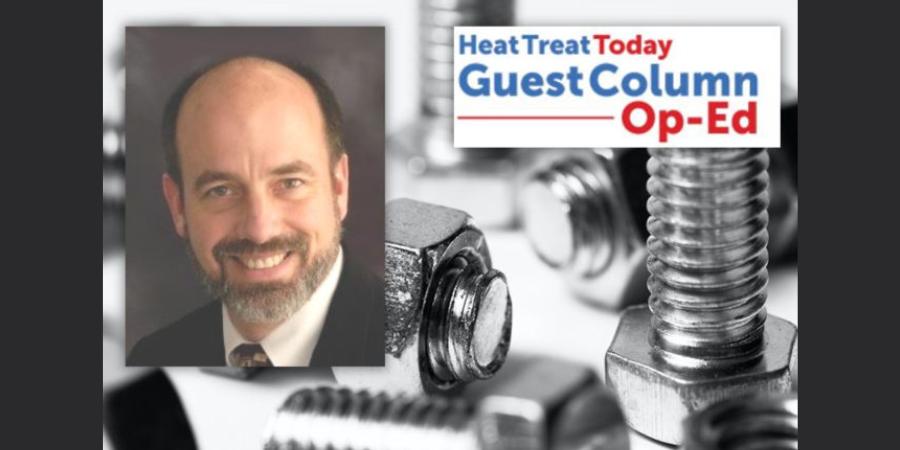
Hawthorne is a heat treat specialist in Acument’s North American facilities and handles the heat treat systems, the system’s compliance, and quality assurance for heat treat within his organization. (Acument makes fasteners—nuts, bolts, rivets, washers— for the auto industry.)
Here’s an excerpt taken from the transcript of the second podcast:
 DG: James, how would you explain CQI-9 to someone who has essentially zero understanding of what it is?
James Hawthorne (JH): CQI-9 is Continuous Quality Improvement. The purpose behind it is to put together a system that will help you manage and control your process, and at the end of it, the product that you’re delivering to the end user. The intent is to give you those guidelines to help avoid potential spills or escapes or whatever else may come with that.
DG: It’s mostly heat treat related, yes? Or is there more than just heat treat there?
JH: It is the entire system of heat treat. If you look at the heat treat system assessment, the first portion of it is quality based. The second portion (Section 2) is the floor responsibilities, things that are on task that are being completed. And third, you get into the maintenance and the pyrometry portion of it, very specific to the pyrometry and very specific to atmosphere control. At the end of it, there are some very specific induction questions, because when it comes to induction, there is no real furnace at that point, so you want to focus on those key elements of induction.
DG: James, we’d like to pick your brain a bit on this. Let’s jump into some questions on the HTSAs, as we’ll refer to them, heat treat system assessments, and job audits. Let’s go right to the basics: What is an HTSA and what is its purpose?
JH: HTSA, heat treat system assessment, is a tool that has been developed to help you evaluate how you manage your heat treat system for effectiveness: effectiveness in quality management and effectiveness in the floor responsibilities. Like I mentioned earlier, understanding that through aspects of training and training effectiveness and into the final section of atmospheric control and atmosphere management and reaction to those.
The purpose here is to have one system, one document that is the rules of engagement for doing heat treat in the automotive world. What this does is allows the automotive industry to give you one spec, one thing to follow. As opposed to having, say Ford, give you ten questions where none of them are exactly the same as FCA or nine of them are the same as Ford Motor Company, where one of them has a specific question. This encompasses all of those wants and needs from the auto industry to protect themselves, to protect the end user out there in the field that may be using that heat treated component.
To listen or read more about the CQI-9 pyrometry section, go to www.heattreattoday.com and search “Heat Treat Radio CQI-9”
Heat Treat Radio:
Justin Rydzewski and James Hawthorne on CQI-9 Rev. 4
(Part 3 of 4) – Process Tables & New Resources
In this third episode, the trio talks about process tables, their importance, and key information on how to read this revision of CQI-9.
Here’s an excerpt from part 3:
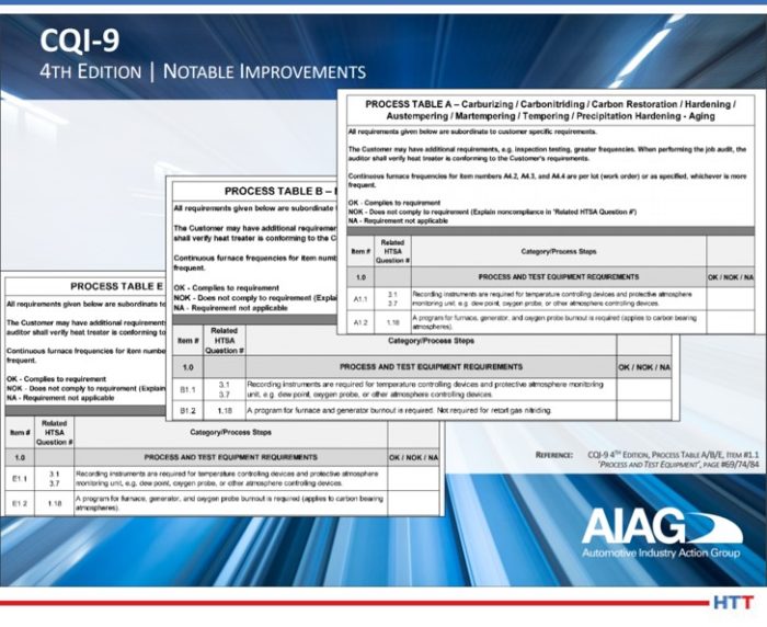
JH: The heat treat system assessment (HTSA) covers the heat treat system and its assessment. There are very unique processes that are covered by CQI-9 and are captured in the process table section of the CQI-9 document.
Process Table A covers carburizing, carbonitriding, carbon restoration, austempering, and precipitation hardening or aging. Section B covers nitriding and ferritic nitrocarburizing. Process Table C covers aluminum. Process Table D covers induction. Process Table E includes annealing and normalizing the stress relief. It goes up to process Table I.
There is a process table for each unique type of heat treat that is out there in the industry and this allows some very specific topics to be covered in those types of processes.
The first portion of it is Process and Test Equipment Requirements. What are the rules of engagement for those items? The same thing for pyrometry. There are specific call outs in the process tables. If this is part of your system, you have to play by these rules. Some of them will point you to specific sections of pyrometry. So, if you’re looking at the thermocouple and calibration of thermocouples, the process table is going to tell you that you shall conform to section P3.1 which covers all of those.
It also covers the process monitoring frequency. How often do you have to check your temperatures? What are the rules of engagement? If you have a batch style furnace that covers that process, it has certain rules for you to manage your batch process.
Then you get into things like inspection – Section 5 of the process table covers things like quenchant and solution test parameters, and the rules for checking that.
What’s really nice about the document is that it’s set up in a way where you can go to the HTSA right from the process table to see if you’re compliant to what’s listed there as the shell statement and the requirements or the frequency for checking those.
To listen or read more about the CQI-9 pyrometry section, go to www.heattreattoday.com and search “Heat Treat Radio CQI-9”
Heat Treat Radio:
Justin Rydzewski and James Hawthorne on CQI-9 Rev. 4
(Part 4 of 4) – Expert Advice
In this final installment, Doug Glenn, Justin Rydzewski, and James Hawthorne field opinion questions as well as practical implementation questions of the new CQI-9 Rev. 4.
Here’s an excerpt from the transcript:
DG: Has CQI-9 been effective in the automotive industry?
JH: I think, 100%, Doug. It’s like IATF—all of the automotive industry has to be compliant to that. Same thing with CQI-9. It provides that commonality for all heat treaters in all the different processes that are employed at their facilities, or the multiple facilities that they may have. For a company like ours, we have eight companies in North America. For the North American side of things that have heat treat furnaces in them, we have induction furnaces, we have carbonitriding furnaces, and we have stress relief furnaces. So that commonality even helps us internally with our management system and how we take steps to provide that common approach and compliance to CQI-9.
JR: I think that also bodes well up the ladder for the OEs. The more people, the more sources that you can go to in order to have work done and have it what you expect it to be, from a quality standpoint.
I think one of the things that CQI-9 has done really well is they’ve made a concerted eff ort to make that document easier to understand and to simplify things down to just its bare bone necessities, whereas some of the other specifications that exist in industry can be lacking.
The intent of CQI-9 was, to a large extent, to be something that you can do yourself and implement yourself. We’ll provide you with the guidance, put it in simple terms, and give you all the research you need to support this on your own.
To listen or read more about the CQI-9 pyrometry section, go to www.heattreattoday.com and search “Heat Treat Radio CQI-9”
CQI-9 Rev. 4 on Heat Treat Radio: What Will You Learn from the Experts? Read More »
 Source: