
 Safety shutoff valves are the last line of defense against a potentially catastrophic incident. When conditions require, they interrupt the flow of fuel to the burner(s) and oven. There are many options when selecting fuel safety shutoff valves for your application. The construction and application of these devices is highly regulated by interlocking standards created by many different organizations. The goal of this article is to clarify how to comply with the most common standard affecting the reader: NFPA 86.
This column appeared in Heat Treat Today’s 2021 Trade Show September print edition. John Clarke is the technical director at Helios Electric Corporation and is writing about combustion related topics throughout 2021 for Heat Treat Today.

Technical Director
Helios Electric Corporation
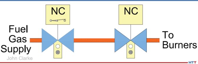
Source: Helios Electric Corporation
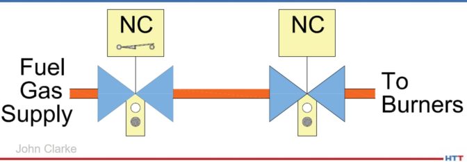
To start, we must define our terms. The 2019 edition of NFPA 86* defines a safety shutoff valve as a “normally closed valve installed in the piping that closes automatically to shut off the fuel, atmosphere gas, or oxygen in the event of abnormal conditions or during shutdown.”1 A valve is “normally closed” (NC) if it closes automatically when power is removed. A furnace or oven typically has as few as two or more safety shutoff valves. [Author’s note: If the system uses radiant tubes for heating, and all the criteria are met, it may be acceptable to use only one valve in series, but this exception is not recommended by the author and will not be covered in this article.] There are two common arrangements for safety shutoff valve arrays—the Simple Double Block (Illustration 1) and the Double Block and Vent (Illustration 2). While both arrangements are compliant with the current version of NFPA 86, the vent is NOT required. In other words, Illustration 1 and Illustration 2 below are both acceptable.
The simple double block arrangement consists of two automatic, normally closed (NC) valves piped in series. It provides redundancy—both valves must leak for fuel gas to pass to the burner system. A double block and vent has two automatic, NC valves piped in series with a third automatic normally open (NO) valve installed between the NC valves. The purpose of the NO valve is to provide a path for any fuel gas leaking past the first NC valve to move to a safe location. Whether one should deploy a double block and vent approach depends on several considerations: Is the NO valve supervised? Is the selected vent location safe? And how will the system be inspected?
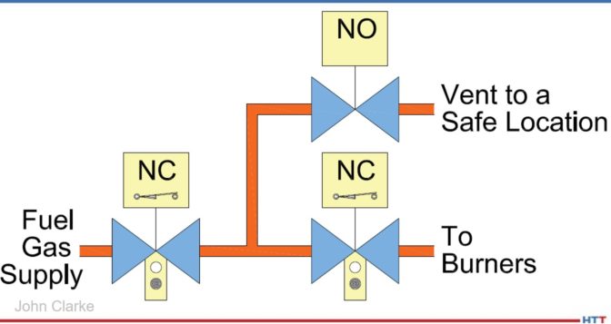
To start with, if the NO vent valve’s coil or wiring fails, it will remain open even when the system is operating—venting fuel gas. This is not only expensive, but high concentrations of vented fuel gas are an environmental and safety hazard. The solution to this concern is installing a monitored vent valve that only opens the NC valves after the vent valve is proven to be closed. This is typically accomplished with a proof-of-closure position switch that only closes after the vent valve is fully closed.
The next concern is the location and maintenance of the vent. The vent must terminate at a safe location that can accept the entire flow of fuel gas in the event of a failure. Therefore, hazards such as fresh air intakes and sources of ignition must be avoided at all costs. It is also important to periodically inspect the vent piping to ensure it remains unobstructed—insects and rodents may find the vent line a comfortable place to nest and bring up their young.
The last challenge is the periodic inspection of the vent valve and the vent piping—it is generally a challenge to test whether a vent line meets the design criteria, and leaking fuel gas can be vented without excessive backpressure.
A simple double block provides redundancy without the complexity of the vent. Good design practice, with proper valve selection, combined with proper fuel filtration greatly improves the reliability and longevity of both systems.
Valves used for safety shutoff valve applications must be listed by an approval agency for the service intended.2 Furthermore, depending on the flow rate, the valves must be equipped with either a local indicator showing the valve position and a means to prove the valve is closed.
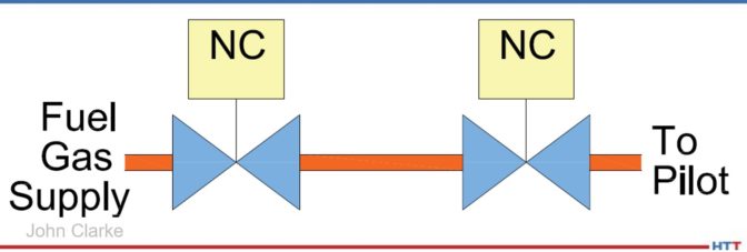
For fuel gas flows below or equal to 150,000 BTU/hour, two safety shutoff valves in series will suffice. See Illustration 3 below. This is very typical for pilot lines.
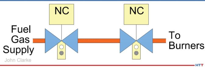
For fuel gas flows greater than 150,000 BTU/hour and less than or equal to 400,000 BTU/hour, two safety shutoff valves in series with local position indication are required. Local indication is generally a window where an operator can see the actual position of the valve—open or closed—without relying on any electrical circuit or pilot light. See Illustration 4 below.
For fuel gas flows greater than 400,000 BTU/hour, NFPA 86 requires two safety shutoff valves in series with local position indication. One valve must be equipped with a valve closed switch (VCS) that closes after the valve is fully closed, or a valve proving system (VPS) that runs a tightness check which must be utilized. The signal from either this VCS or VPS must be included in the burner management system’s (BMS) purge permissive string to ensure no fuel gas is flowing during the system preignition purge. The VCS must not actuate before the valve is fully closed. This is typically accomplished by using valve overtravel, where the valve closes first, then the mechanism continues to move until the VCS is actuated. This arrangement is depicted in Illustration 5 below.
For the arrangement depicted in Illustration 5, NFPA only requires one valve be supervised with a VCS—the additional costs of supervising both valves are very low and will enhance safety.
Whatever the method used to shut off the fuel to burners or pilots, the array of valves must be inspected and tested annually or per the manufacturer’s recommendations, whichever period is the shortest. All systems must be designed to be tested—with provision provided to cycle valves in test mode and the ability to measure any potential leakage. We will explore how a fuel train should be “designed to be tested” in an upcoming article.
The one thing to always remember—safety shutoff valves are always deployed to provide redundancy, so that any one component failure will not prevent a safe interruption of fuel gas; but, as with all systems, there may be unforeseen events that can lead to complete failure. Only qualified people should design, operate, and maintain combustion systems.
References
[1] National Fire Protection Association – NFPA 86 Standard for Ovens and Furnaces 2019 Edition (NFPA, Quincy, Massachusetts, May 24, 2018) 3.3.82.2 pp 86-14.
[2] National Fire Protection Association – NFPA 86 Standard for Ovens and Furnaces 2019 Edition (NFPA, Quincy, Massachusetts, May 24, 2018) 13.5.11.1 pp 86-49.
About the Author:
John Clarke, with over 30 years in the heat processing area, is currently the technical director of Helios Electric Corporation. John’s work includes system efficiency analysis, burner design as well as burner management systems. John was a former president of the Industrial Heating Equipment Association and vice president at Maxon Corporation.