What's the future of ferritic nitrocarburizing and how does it compare to other hardening processes? When it comes to metal hardening, there are many variations on central processes, including recent innovations in how to apply hardening processes.
This Technical Tuesday brings you a quick overview of how hardness technologies differ, specifically nitriding and FNC, and how certain heat treaters have developed these specific hardness technologies.
Understanding the Various Hardening Processes
If you want to know the future, the best you can do is understand the past and present. Let’s begin with looking at the most common hardening processing methods. Here are a few excerpts from “Elevate Your Knowledge: 5 Need-to-Know Case Hardening Processes” by Mike Harrison, engineering manager of Industrial Furnace Systems Division at Gasbarre Thermal Processing Systems:
Read more about these 5 processes in Mike Harrison's article. Click to read.
Carburizing: “Gas carburizing is a process where carbon is added to the material’s surface. The process is typically performed between 1550-1750°F, with carburizing times commonly between 2-8 hours [this spec is disputed, and times may run up to 24 hours]; of course, these values can vary depending on the material, process, and equipment. The most common atmosphere used for atmosphere gas carburizing is endothermic gas with additions of either natural gas or propane to increase the carbon potential of the furnace atmosphere.”
Nitriding: “Gas nitriding is a process where nitrogen is added to the material surface. The process is typically performed between 925-1050°F; cycle times can be quite long as the diffusion of the nitrogen is slow at these temperatures, with nitriding times typically ranging from 16 – 96 hours or more depending on the material and case depth required. Nitriding can be performed in either a single or two-stage process and has the potential to produce two types of case, the first being a nitrogen-rich compound layer (or “white layer”) at the surface that is extremely hard and wear-resistant but also very brittle.”
Carbonitriding: “Despite its name, carbonitriding is more closely related to carburizing than it is to nitriding. Carbonitriding is a process where both carbon and nitrogen are added to the material surface. This process is typically performed in a range of 1450-1600°F [this spec is disputed, and temperatures may go up to 1650°F] and generally produces a shallower case depth than carburizing.”
Ferritic Nitrocarburizing (FNC): “In the author’s opinion, just like with carbonitriding, ferritic nitrocarburizing (FNC) is named incorrectly as it is more closely related to nitriding than it is with carburizing. FNC is a process that is still mostly nitrogen-based but with a slight carbon addition as well. The added carbon helps promote compound layer formation, particularly in plain carbon and low alloy steels that do not contain significant nitride-forming alloys. This process is typically performed in a range of 1025-1125°F with cycle times much shorter than nitriding, typically 1-4 hours.”
Low Pressure Carburizing (LPC): “Low-pressure carburizing (LPC), or vacuum carburizing, is a variation of carburizing performed in a vacuum furnace. Instead of the atmospheres mentioned previously, a partial pressure of hydrocarbon gas (such as acetylene or propane) is used that directly dissociates at the part surface to provide carbon for diffusion. After LPC, the workload is transferred to a quench system that could use oil or high-pressure gas, typically nitrogen.”
Nitriding
Learn more about the basics of hardening at Heat Treat Radio. Click to listen,
Gas nitriding, a process over 100 years old, is a hardening process that involves diffusing nitrogen into the surface of steel to create a hard, wear-resistant case. Among many benefits, the part will have enhanced fatigue properties, anti-galling properties under load, and a resistance to softening at elevated temperature. This makes it an excellent choice for the aerospace industry.
There is some recent history regarding problems related to the “white layer”. In a typical microstructure, the “white layer” is a nitrogen-rich surface layer and the diffusion layer exists beneath it.1 It is essential that the surface layer be controlled to avoid an overly brittle part. Mark Hemsath the vice president of Sales – Americas for Nitrex Heat Treating Services, elaborated on this in a Heat TreatRadioepisode:
"Doug Glenn: I assume, with all the modern day technology and whatnot, we're able to control that white layer and/or depth of nitriding layer through your process controls and things of that sort."
"Mark Hemsath: Yes. Nitriding has been around a long time, but one of the problems that they had was controlling the white layer. Because they basically would just subject it to ammonia and you kind of got what you got. Then they learned that if you diluted it, you could control it. That's with gas nitriding. Then plasma nitriding came around and plasma nitriding is a low nitriding potential process. What that means is it does not tend to want to create white layer as much. It's much easier to control when the process itself is not prone to creating a lot of white layer, unlike gas. Now, in the last 10 – 15 years, people have gotten really good at controlling ammonia concentrations. They've really learned to understand that."
"ZeroFlow nitriding is ammonia-based gas nitriding," commented Dr.Maciej Korecki, PhD Eng., vice president of the Vacuum Furnace Segment at SECO/WARWICK Group. "It is distinguished by the fact that the nitrogen potential is controlled by introducing the right portion of ammonia at the right time and only ammonia, instead of a continuous flow of a mixture of ammonia and diluent gas."
"Consequently, the ZeroFlow method uses the minimum amount of ammonia needed to achieve the required nitrogen potential and replenish the nitrogen in the atmosphere, taking into account the situation where no ammonia is supplied to the furnace at all, no flow, hence the suggestive name of the solution," he continued. "Using ammonia alone in the nitriding process, we are dealing with a stoichiometric reaction (as opposed to some traditional methods), that is, one that is uniquely defined and predictable based on the monitoring of a single component of the atmosphere. Therefore, the ZeroFlow process controls very precisely through the analyzer only one gas, obtaining an improvement in the quality and repeatability of the results compared to various traditional methods."
According to Dr. Korecki, the process is about going back to the basics of nitriding: "The inventor of the method is Prof. Leszek Maldzinski of the Poznan University of Technology, who developed the theoretical basis and confirmed it with research. Then, more than 10 years ago, a partnership between SECO/WARWICK and the Poznan University of Technology initiated a project to develop and build the first industrial furnace designed to perform the ZeroFlow nitriding processes. The furnace was launched at SECO/WARWICK's research and development department (SECO/LAB®), where the method has been implemented and validated on dozens of industrial-scale processes."
Ferritic Nitrocarburizing
This nitrogen-based process can produce a deeper compound layer than nitriding, which is great for industrial machinery applications where this deep layer is needed for increased wear resistance and the critical strengthening of a deep case depth is not essential.
FNC has gone through a technical evolution with different heat treaters in the industry developing their own unique applications with method in mind. We'll look at two recent examples: AHT's Super Ultra Ox and Bodycote's Corr-I-Dur.
Edward Rolinski Senior Scientist Advanced Heat Treat, Corp. (Source: https://www.ahtcorp.com/)
According to experts at Advanced Heat Treat Corp. (AHT), Edward Rolinski (Dr. "Glow"), Jeff Machcinski, Vasko Popovski and Mikel Woods, "Thermochemical surface engineering of ferrous alloys has become a very important part of manufacturing. Specifically, nitriding and nitrocarburizing (FNC) processes are used since their low temperature allows for treatment of finished components. They are applied to enhance the tribological and corrosion properties of component surfaces.2 In many situations, nitriding replaces carburizing even if the nitrided layer is not as thick.3 A post-oxidizing step, applied at the end of FNC, leads to significant enhancement of corrosion properties by formation of a magnetite layer (Fe3O4).
"AHT’s newly developed process, UltraOx® Hyper, results in superior wear and corrosion resistance and allows for good control of the parts’ blackness. The latter is very important when the treatment is used for firearms. While the parts’ corrosion resistance improves with nitriding alone, the additional steps in UltraOx® Hyper significantly extend corrosion resistance. AHT is committed to achieving its customers’ desired metallurgical and cosmetic results through R&D and investing in state-of-the-art equipment. These innovations allow for flexibility in these areas."
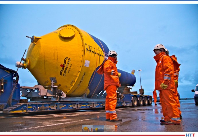
In recent news, wave energy pioneer CorPower Ocean will be using Bodycote's thermochemical treatment, Corr-I-Dur®, for CorPower’s high-efficiency WECs. Image Source: www.waterpowermagazine.com
From Bodycote, they say that their proprietary Bodycote thermochemical treatment “Corr-I-Dur® is a combination of various low temperature thermochemical process steps, mainly gaseous nitrocarburising and oxidising.”
They explain, "In the process, a boundary layer consisting of three zones is produced. The diffusion layer forms the transition to the substrate and consists of interstitially dissolved nitrogen and nitride precipitations which increase the hardness and the fatigue strength of the component. Towards the surface it is followed by the compound layer, a carbonitride mainly of the hexagonal epsilon phase. The Fe3O4 iron oxide (magnetite) in the outer zone takes the effect of a passive layer comparable to the chromium-oxides on corrosion resistant steels.
"Due to the less metallic character of oxide and compound layer and the high hardness abrasion, adhesion and seizing wear can be distinctly reduced. Corr-I-Dur® has very little effect on distortion and dimensional changes of components compared to higher temperature case hardening processes."
How to Implement?
We’ve seen a lot of development in way of nitriding and ferritic nitrocarburizing (FNC), but for many heat treaters, you inherit specific processes and traditions of accomplishing heat treatment and do not have the chance to understand how to implement each process. Read the full 21 point comparative resource at FNC vs. Nitriding
Conclusion
The more informed you are, the better decisions you can make. For example, knowing these recent developments in metal treating and hardening is sure to help you decide whether to shift directions in how you company process parts for electric vehicles, or if you are ready to expand your offerings for your aerospace clients. It is clear that each of these processes have a future all-their-own. It’s up to you to decide whether that future should be yours, too.
For more information on the basics of hardness, listen to the what, why, and how of hardening with Mark Hemsath, an expert on metal hardness and vice president of Sales – Americas for Nitrex Heat Treating Services, on this Heat TreatRadio episode with Doug Glenn, publisher of Heat TreatToday. You can also review the resources below that were referenced in today’s article.
2 “Thermochemical Surface Engineering of Steels”, Woodhead Publishing Series in Metals and Surface Engineering: Number 62, Ed. Eric J. Mittemeijer and Marcel A. J. Somers, Elsevier, 2015, pp.1-769.
3 J. Senatorski, et. al, Tribology of Nitrided and Nitrocarburized Steels”, ASM Handbook Vol 18, Friction, Lubrication and Wear Technology, ed. G. Totten ASM International, 2017, pp. 638-652.
Senatorski, J. Tacikowski, E. Rolinski and S. Lampman, “Tribology of Nitrided and Nitrocarburized Steels”, ASM Handbook Vol 18, Friction, Lubrication and Wear Technology, ed. G. Totten ASM International, 2017.
“Thermochemical Surface Engineering of Steels”, Woodhead Publishing Series in Metals and Surface Engineering: Number 62, Ed. Eric J. Mittemeijer and Marcel A. J. Somers, Elsevier, 2015, pp.1-769.
Heat treat specifications can be tiresome to stay up-to-date on. So it’s great when we find digestible content on AMS2750F to share with you.
In today’s best of the web article, you’ll be able to review the 4 new requirements for process instrumentation and what 18 pieces of information must always be reported in the calibration certificate.
An excerpt:
“The recording tools used on heat treatment plants should not be used to record TUS or SAT sensor temperatures unless it can be demonstrated that the recording channels of the TUS and/or SAT sensors of an integrated system are separated from the recording system of the heat treatment furnace and also meet the requirements of the field test instrument.”
Welcome toHeat Treat Today'sThis Week in Heat TreatSocial Media. As you know, there is so much content available on the web that it’s next to impossible to sift through all of the articles and posts that flood our inboxes and notifications on a daily basis. So, Heat Treat Todayis here to bring you the latest in compelling, inspiring, and entertaining heat treat news from the different social media venues that you’ve just got to see and read!
This week, we check out what's going on in the heat treat community (in person and afar), watch a robot video (it may look familiar, but this time the robot might be at your plant), and read a not-so-heat-treat-but-certainly-funny T-shirt.
Spot, the dancing robot from the previous TWIHTSM, can perform manufacturing site inspections. Using Fluke imaging technology, the robot can monitor site problem areas. What do you think? Does this change the game of manufacturing? Is it a good solution to safety concerns on the shop floor?
2. Water Cooler Talk
What have you been talking about while we were away? Online chatter "around the cooler" yields some interesting insights. Let us know about some interesting fact or episode in your world by tagging @HeatTreatToday on your next post!
Chattin' About Furnaces
.
Influences on Furnace Pumping Time?
Too Basic?
3. Heat Treat Community
In person or online, we can't get enough of the comradery. Let's show you what we're talking about. . .
@Women in Manufacturing!
To China and Beyond!
Nope, this is not a throwback picture. This week, the China Heat Treating Association hosted a live edition of the 2020 Shanghai Heat Treatment Exhibition. Booth visitor turnout was strong with many mfrs planning to invest in their production capacity.https://t.co/5Tifckc7Jh. pic.twitter.com/kYgrFy5C6Z
Heat TreatToday publisher Doug Glenn wraps up this three-part series with Pelican Wire experts by talking with John Niggle from Pelican Wire about thermocouple insulation types and considerations.
The first two episodes cover the history, types, vocabulary, standards, and other basics of understanding how thermocouples work. Listen to the previous episodes of the series here.
Below, you can either listen to the podcast by clicking on the audio play button, or you can read an edited transcript.
The following transcript has been edited for your reading enjoyment.
Doug Glenn (DG): Welcome to Heat TreatRadio!
John Niggle (JN): Yes, it's good to see you again, Doug. I know we've run into each other a couple of times out there in the field. I'm looking forward to having the opportunity to do all of this stuff in person again.
DG: It will be nice. Before we hit the record button, we were talking about shows this fall and hoping that they happen because you, like I, are ready to get out and go.
You are the business development manager for Pelican Wire. If you don't mind, give us just a little bit of background about you and about your experience in the whole thermocouple world.
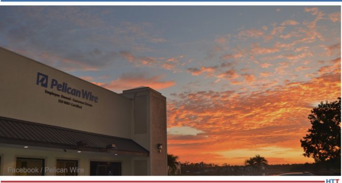
Pelican Wire headquarters
JN: Sure, absolutely. As you said, I am the business development manager at Pelican Wire. I've been at Pelican since 2013 so we're working out my eighth year here. I'm a career industrial sales representative. I do have previous experience also, actually, in the process instrumentation industry. Way back when, before I even knew how to spell thermocouples, I was selling that stuff when I first got out of college. My career has, sort of, gone full circle, let's say.
DG: Very nice. Well, you've got plenty of years of experience, which is great. We've had two previous episodes with your colleague, Ed Valykeo, and we covered a good bit of stuff. We covered a lot of basics in the first episode. We covered standardization, and things of that sort, in the second episode. I want to encourage any listeners who haven't listened to those episodes, feel free to go back, Google “Heat TreatRadio” and search for “Pelican Wire” and listen to episodes 1 and 2.
John, you and I want to move forward. I'm always kind of curious about this question: From your perspective, with your experience, why do we use thermocouples? Let's talk about what they are and why we use them.
JN: First of all, we have to assume that somebody is trying to measure the temperature of some sort of a process- a process or an event of some kind. That's basically what they're trying to do. Compared to other devices like RTDs, bimetal thermometers, liquid expansion state change devices and so forth, thermocouples are robust, they're inexpensive; they're repeatability, they're ease of use and size -- all of those factors lead them to be more widely used than another sort of thermal measurement device of any kind. It is the preferred method.
On top of that, I mentioned the expense part. Because they're relatively inexpensive, there are certain industries, the heat treat industry and smelting industry, for example, consider these as, actually, consumable or disposable. So, the cost factors in significantly in the industry that we're talking about here.
DG: I live in western Pennsylvania and the town where my wife grew up, there was an old Leeds and Northrup manufacturing plant. I believe they made the consumable thermocouples for melt shops. You would, basically, throw the thermocouple in and it would melt quickly but it would give you a response during that time.
CLICK to Listen!
JN: Right. And, as I mentioned earlier, the response factor is important, or that's one of the factors considered, when people are looking at thermocouple wire. And, you're correct, Ed Valykeo, as you mentioned, has 40 years of experience in the industry and has seen exactly the same sort of thing that you're talking about where people will just tack weld it onto something that gets thrown into a furnace or it gets thrown into a melting pot or something like that, and they're looking for that instantaneous temperature.
If you don't mind, I'll tell you that we've done some work, actually, in the aerospace industry and we had a customer that we sold significant, literally miles, of thermocouple wire to (when I say aerospace, it was specifically for space exploration) and this was because of whatever we had done with the insulation. I can't tell you, because it was before my time, but this is what was relayed to me- they were able to get another 3 - 4 seconds of temperature measurement out of that wire. That critical, extra data for them made all the difference in the world.
DG: We're going to get to the insulation part which should be interesting. You won't have to tell us any trade secrets, but we are headed in that direction anyhow.
So, different types of thermocouples. Again, just a review question for us. Why use them? Why the different types and why are we using different types?
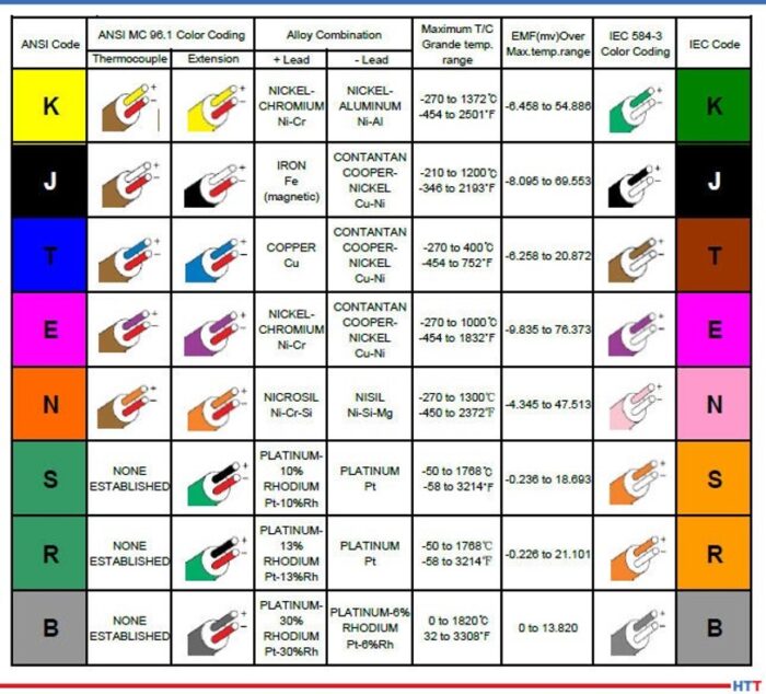
JN: Forgive me, Doug, and the rest of the audience, for that matter, if I end of repeating some of the things that came out in the previous episode. Basically, when you're talking about thermocouples, there are the two chemistries; for lack of a better term, you have “base” and “noble” metals. The base metals are really the metals that we focus on at Pelican. The noble metals are the more expensive ones- rare earth metals, tungsten, titanium, platinum and all those sorts of things that people spend exorbitant amounts of money on. There are purposes for those, but, typically, what you're going to see in the heat treat industry, in particular, you're going to see a lot of the base metals.
I like to say that, truly, the 20 gauge K, in particular, is the 800 pound gorilla in the room. It's almost considered, and I think it would be by people in the industry, a commodity. There are untold miles of that wire that are used in the heat treating and smelting industry. K is used, really, because of the temperature range. It fits in well with what people do in the heat treating industry. It is good for temperatures from zero up to around 1260 C. It's inexpensive, it covers the ranges that those people are looking for, and, again, it's the 800 pound gorilla in the room when it comes to temperature measurement in the heat treating industry.
Click to read the Heat Treat Today Original Content article on thermocouples.
The other types such as J comes up periodically, particularly if you're looking at lower temperature ranges. You won't see it quite as often in the heat treating industry. You will see it somewhat, but not to the degree that you would K. The J thermocouple wire has an iron leg so it does oxidize and you need to be careful about that sort of thing. Type T thermocouple wire has a narrower range. It has very good response times in cryogenic and cold temperature applications. The higher, upper end of type T thermocouple wire, typically, wouldn't be of terrible interest to the audience that we're involved with here, for the most part, because the upper ends around 370 to 400 C degrees, in lab environments; that's where it's going to be the most popular.
There is also type E. It's a higher temperature, as well. Response time. Broader range is a little bit better than K at lower temperature ranges. An interesting one is type N that you will see fairly often in the heat treating industry. For those people not familiar with type N, it is different alloys than type K. It covers virtually the same temperature range that type K does and will, actually, have less drift than type K. It is more expensive because of the alloys that it is made of, but, again, if you're interested in less drift, then type N is worth looking at. It hasn't quite caught on in the US the way it has in, say, Europe, in particular, and that really has to do with the infrastructure of the instrumentation. People have instrumentation that is either calibrated for K or J or something like that. Now, there is instrumentation out there, now, that would use K and N both, so we may see more, particularly, in the aerospace industry I would think it would become more and more popular.
DG: That's helpful. It's always good to hear those things over again.
How about the parameters and/or the factors that need to be considered when you're constructing the wire to start with? What do we need to be worried about in that area?
JN: I don't know if I like the word “worried” exactly, Doug. It's more, what do we need to think about? What do we need to be concerned about? Besides the metallurgy that we just talked about, we need to think in terms of what the sensor is actually going to look like. Is it just the wire? Thermocouple wire, by itself, can be a thermocouple; that's it, without any protection or anything like that.
As I mentioned earlier, you can tack weld it to an ingot, or something like that, and there you go. You don't have any probe, there is no thermal well to protect it or anything like that. But, what we do need to think about, then, is the process that it's going to be involved in. Where is it going to be used? Is it going to see an environment where there is a flow. Is it going to see an environment where somehow the thermocouple wire can become damaged? In that case, then, we're headed in the direction of talking about what our customers are interested in. And for a customer for Pelican Wire, we're mainly talking about people who actually assemble thermocouples – they make the connections, they have the molds and all that sort of thing.
To be clear, Pelican Wire just makes wire. And, again, the thermocouple wire can be used as a thermocouple, but a tremendous amount of wire is actually connected to some sort of a sensor or a probe, as I said, and is protected in a thermal well or something along those lines.
"But, what we do need to think about, then, is the process that it's going to be involved in. Where is it going to be used? Is it going to see an environment where there is a flow. Is it going to see an environment where somehow the thermocouple wire can become damaged? In that case, then, we're headed in the direction of talking about what our customers are interested in."
John Niggle
DG: Do we also have to be concerned with oxidizing, carburizing atmospheres, corrosive atmospheres? Is that, also, something that we need to be aware of?
JN: Absolutely. And that is one of the reasons you will see a probe thermocouple is because the wire is protected from that atmosphere. Nearly all of the wires that we talked about would be affected, particularly, in say, like a sulfurous environment; it would be subject to corrosion, oxidation and something along those lines.
Other factors, of course, are the accuracy and how much space we have. Believe it or not, if it's going to go into a small orifice, then we need to think about what the age size is going to look like. And then the environment: Is it going to be abrasive? Is there movement? Is there some sort of braiding motion that could wear a hole in the wire in the insulation and so forth? There are a lot of things to think about.
DG: And, it would probably be a good idea, especially if our heat treat people are running anything outside of the norm, regardless of what it is, whether it be atmosphere, configuration, fixturing, if there is anything outside the norm, they would probably be wise to mention it to the thermocouple wire and/or thermocouple probe manufacturer and make sure that they know so that you guys can get help get the right thing on there in their furnace.
JN: Yes, absolutely. At the end of the day, we work with this every day. We have design engineers on staff who can assist with technical questions and so forth and, of course, our customers, and the actual thermal wire assembly people, this is what they do every day of the week.
“I'll tell you that we've done some work, actually, in the aerospace industry and we had a customer that we sold significant, literally miles, of thermocouple wire to (when I say aerospace, it was specifically for space exploration) and this was because of whatever we had done with the insulation.”
DG: Let's talk about something a little bit new, I guess, to our conversation here in this 3-part series, and that is the insulation that's going to go around these wires. Can you tell us what are the different types of insulations and what are the advantages and/or disadvantages of each, and why would we be using them?
JN: I'll break it down into, what I would call, the four basic categories. That would be an extruded insulation, insulations that are tapes, fiberglass insulations that are routinely worked with and then, of course, high temp textiles. High temp textiles, in particular, would be of interest to the audience here in the heat treat metallurgy world.
Extruded insulations can be a variety of thermoplastics. A term that, I think, Ed has probably mentioned before and we've talked about before is extension grade wire. That typically has a PVC insulation on it and the reason PVC works for that is that it's cheap and extension grade wire, typically, does not see the sorts of high temp environments that you're going to see in processes. It's really a signal wire that takes the signal from the probe or from the sensor to the process control device.
DG: So what kind of temperature tolerances can the extruded wire handle? Are we talking 300, 400 degrees? I guess you talk C, I talk F.
Teflon frying pan
JN: We talk whatever language our customer likes to talk, but we do talk C quite a bit. So, PVC is quite low, it's in the 200s F. But, when you're looking at fluoropolymer insulations (and Pelican is really a high temp house, so we focus on the higher temp insulations) you have FEP and PFA, those are in the 200s. PFA actually goes up to 260. So, you can see, it's probably not suitable for heat treating applications, smelting and that sort of thing. The advantages to those compounds would be that you're going to have abrasion resistance. Think about your Teflon frying pan: it's slick, it's smooth. So, if you're in an environment where there is some movement, it will be good for that. And, of course, it will have excellent moisture resistance and chemical resistance. Those would be the advantages to the extruded wire. The other advantage would be, because you'll have a thinner wall than you will with the other insulations, you'll have some more flexibility. So, if you have a type N radius, you can go around a corner easily.
The next step up, in terms of temperature resistance, would be the tapes. Basically, in that area, you're looking at PTFE tape, mica take and capped-on tape or polyamide tape. Those will give you slightly higher heat resistances. The mica, in particular, would give you more. (Mica, as a matter of fact, is used as a supplement to the PTFE to give it even higher heat resistance.) Mica will go up to 500 C, PTFE and the polyamides match, in terms of heat resistance, the extruder products around 260. What they do give you, again if you use the tapes, is the heat resistance you're looking for, some abrasion resistance and the moisture resistance. You'll have less flexibility because those products are stiffer, but they're also going to be a little bit lighter weight unless you incorporate the mica into it. Then, when you do that, you're going to end up with an even stiffer wire and it will be a little bit heavier, and all those will be larger in diameter than an extruded wire. If you look at an environment where you need to poke the wire through a hole and that hole is an eighth of an inch, you need to think really hard if what you're doing is going to work.
DG: So you've got extruded and you've got tapes.
JN: The next step after that would be fiberglass. In the case of fiberglass, you have E glass and S glass. Of the two, E glass would have the lower temperature resistance and you're looking at 482 C on the high end. For S glass, you're up to 704 C. Now you're starting to talk about insulations that you will see in the heat treat environment; it's quite common, especially on the S glass side where you're looking at the 704, you'll see a lot of people that need 500 C for whatever reason. The advantage, obviously, to the glass, as I mentioned, is the higher heat resistance.
There are disadvantages. Think about fiberglass for a minute. We actually have to saturate the wire to keep it from fraying without it ever really experiencing any abuse. If we don't saturate it, then the wire can fray, and you can get fiberglass in your fingers even, which is unpleasant. So, fiberglass has some disadvantages like that. If you put it in an environment where there is some movement, abrasion, vibration or something like that, it can be problematic. Also, it's going to be stiffer because it's saturated, typically. Sometimes you'll even see those saturants even cause problems in a heat treat environment where, if it gets too hot, the saturant can leave an ash behind. You're going to lose flexibility, as I said. You're not going to have the abrasion resistance, the chemical resistance or the moisture resistance that you're going to get from an extruded product.
The other one that we see, again, literally miles and miles and miles of, in the heat treat world would be what's called Refrosil and Nextel, (those are both, actually, trade names). We're talking about vitreous silica and ceramic. Again, those are, what we call, high temp textiles. Now, you're looking at products that are in the 1200 C range. Ceramic goes up to 1204, vitreous silica is in the 870's. Again, there are some of the same disadvantages with those that you're going to have with glass. It's going to be somewhat fragile. We don't saturate those because the saturants are not going to hold up in the environments that they're going to be placed into, so you would have that ash residue left.
Again, it will be stiff, it will be even larger in diameter than the fiberglass, which is larger than tape which is larger than the extruder products. Of course, you're not going to have the abrasion resistance, the moisture resistance or the chemical resistance. But it does protect the wire in those elevated temperature environments that are critical for the heat treating industry.
DG: Let's back up a bit. I want to understand something you said. You said, in the fiberglass, it is saturated and in the textiles it's not. I want to know what you mean by saturated.
JN: It's either a solvent-based or a water-based saturant that is applied to the wire to protect it. Think in terms of a varnish. It would be like a protective coating. Again, it just keeps the exterior of the wire, the bare wire, from being exposed. It's a coating, but we call it a saturant.
DG: High temperature textiles tend to be the stuff we're using, in the heat treat industry, probably most.
JN: Yes. Again, when I mentioned the 800 pound gorilla in the room, the 20-gauge K with the vitreous silica or the Refrosil would be an extremely popular product in the heat treating industry, absolutely.
DG: Let me ask you a very, very fundamental question. I'm curious of your answer to this. Why do we insulate wires at all? Is it done to protect from temperature or is it done simply to protect them from crossing with each other and grounding or shorting out? Why do we insulate?
"I'll go back to something that I know Ed talked about: the Seebeck effect. You have this loop; if you don't have that loop, then you don't have anything. You don't have the EMF, the electromotive force, that you're looking for."
John Niggle
JN: It is the second part. When you look at any wire construction, the two singles have to be insulated from each other. I'll go back to something that I know Ed talked about: the Seebeck effect. You have this loop; if you don't have that loop, then you don't have anything. You don't have the EMF, the electromotive force, that you're looking for. We do make a wire that is not duplex, but, typically, what you're going to see is a wire that has two singles and then it's duplexed with an insulation over the top. We do make a wire that the two singles are jacketed in parallel and then no jacket is placed over the top but that is for an application that wouldn't be suitable for the heat treat industry.
DG: I asked that question, because for those who are unbaptized in this conversation, it's kind of interesting. So, we're talking about insulation and we're doing a lot of conversation about temperature ranges and, for someone who wouldn't think so, they would say, "Well, that means you're insulating because of temperature." But, really, the reason you're insulating wire is for electrical. It's to keep them apart. It's just how high of temperatures those insulations can handle, not that you're insulating the wire to keep them cool. Right?
JN: Absolutely not.
DG: That may sound very basic, but there may be people that think that, so I want to get that on the table.
JN: Most of the people in the audience are probably familiar with this already. Typically, what happens is the wire is stripped so we have exposed ends. And then those ends, as we mentioned earlier, can be tack welded onto something or they can just be out there. The thermocouple world, by the way, is an incestuous world where we have customers, we kind of compete with those customers, some of our customers compete with others of our customers but then they buy supplies from each other. You probably already know that from talking with other people in this industry. At any rate, the wire is stripped and then it's either tack welded or it's connected to some sort of sensor or probe of some kind.
DG: It's a tangled web, the whole thermocouple world. You've got customers, yet you sell to certain suppliers who also sell to those customers. It can be complicated! But that's OK, we'll let you guys worry about that; we just want to make sure the thermocouples are good and we'll be in good shape.
Another question for you: We talked about the process and a lot of different environments about what type of thermocouple you should use, but does the process being monitored influence the type of insulation that should be used? Obviously, temperature is going to have an impact, but is there anything else?
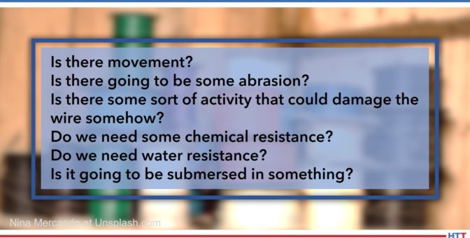
JN: Yes. Let's circle back to what we talked about earlier just a little bit. When you look at the process, you need to think of what is going to happen to that wire? Is it going to see, first of all as you mentioned, the temperatures? That is certainly important so that comes into play with the insulation. But, we need to think about, Is there movement? Is there going to be some abrasion? Is there some sort of activity that could damage the wire somehow? Then, we need to look at the chemicals, like we talked about. Do we need some chemical resistance? Do we need water resistance? Is it going to be submersed in something? Those things all need to be considered.
Again, as I mentioned earlier, the actual placement of the wire. Does it need to be inserted in a hole? At Pelican, we produce wire down to 40 and actually 44 gauge which, I think, will probably be stunning to most of the people in your audience because, again, 20-gauge K is what these people think about. In the heat treating industry, what you see is they need a robust wire, something that's going to be able to handle those temperatures and a large conductor like that.
Another thing to think about, actually, is a bend radius. Are you going to put the wire somewhere where it needs to go around a corner, around a bend? Then, are you better off using a stranded wire? A stranded wire is going to have more flexibility. You can buy a 20-gauge stranded wire, you can buy 24-gauge, 28-gauge, 36-gauge.
DG: Now, what do you mean by stranded?
JN: Stranded wire would be instead of just one solid 20-gauge conductor, you have multiple strands that make up that 20-gauge. But, if you think about it, multiple strands of wire will actually be more flexible. You'll still get the same results, but it will be more flexible if you need to go around a corner or if you need to insert it into something.
DG: It's almost like a braided wire as opposed to a solid.
JN: Yes. Now braiding is a little bit of a different process. When we're talking about stranded wire, it's, basically, just spiral. Braided is more crossed into each other, which, coincidentally, is the way that the fiberglass and the high temp textile insulations are made – those are actually braided. And, by the way, I'll just toss this out, it's made on equipment that really hasn't changed since the ‘20s. I'm not talking about the 2020s, I'm talking about the 1920s! Rumor has it, some of that braiding equipment was, actually, designed by Thomas Edison. I'm not sure if that's really true. But that is the process used to apply the fiberglass and high temp textiles.
DG: So, anything else as far as any other considerations we need to take into consideration when we're talking about choosing insulation? If not, that's fine.
JN: I think I covered them, Doug.
DG: At Pelican Wire, your company, I know you guys deal with a broad number of markets, I'm sure, one of them being heat treat. What do you see as any special demands or special concerns that are, maybe, unique or, at least, inherent in the heat treat market?
". . . what you see is insulations that are higher in temperature resistance, as well. In some cases, as I mentioned earlier, in ovens where there is a saturant involved, we could see ash. Some people ask that saturant not be applied to the fiberglass and that's certainly something that can be done."
John Niggle
JN: For the heat treat market, again, I'll go back to what I said earlier, we see a lot of 20-gauge K used. It's because of the higher heat requirements, the higher heat that is involved with the processes of heat treating. Secondly, what you see is insulations that are higher in temperature resistance, as well. In some cases, as I mentioned earlier, in ovens where there is a saturant involved, we could see ash. Some people ask that saturant not be applied to the fiberglass and that's certainly something that can be done.
Sometimes we're even asked to not put tracers. We go back to what we talked about earlier with the metallurgy- you have two legs, a positive and a negative leg. Well, how do those end users tell those legs apart if they look similar, if they're an alloy of some kind? So, we put a tracer wire in there so you have a red leg and a yellow leg, in the case of type K, or sometimes you just have a red leg depending on what they ask for. Those tracers can, actually, cause problems, too, if the ovens are hot enough and they are in there for long enough times. We even have customers who ask us not to put tracers in their wire, for that matter.
Accuracy, of course, is extremely important. I know that Ed, in a previous episode, talked about standard limits, special limits and all that sort of thing. Typically, you're going to see special limits used in the heat treat industry and, in some cases, we're asked even for special calibration points. In previous podcasts, I've heard you talk with other people about AMS2750 and how that comes into play. It is extremely critical for the folks in the heat treating industry and something that clearly a thermocouple wire producer has to understand.
Episode 1 of 3 of AMS2750 series
DG: Let's say you've got a customer that calls you and wants to talk about their thermocouple needs, let's say there is some sort of special need. What would you suggest they have, in hand, when they call you? What do you need to know from them to help you do a better job with their thermocouple needs?
JN: Honestly, the first question we do ask is: What temperature are you going to be running this at? How hot are we going to be? We, absolutely, need to know that. That helps us narrow down the alloy that we might be looking at, whether it's type K, type J, type E, or whatever. And then, of course, it's a natural thing to dial in the insulation after that. Quite honestly, one of the things that frustrates me is when people say, "I need Teflon." Well, OK. Do you need FEP or do you need PFA? Those are both fluoropolymers like Teflon is. We need to talk about temperature resistance, so don't tell me you just need Teflon. We do need some specifics when it comes to that sort of thing. Again, we talked earlier about stranding and stranded wire. Do you need some flexibility? What gauge size do you think you need? How robust does this wire need to be? Those are some of the key factors we need to know about.
DG: Let's say, for example, somebody does want to get a hold of you or Ed, your colleague who was on the first two episodes, how is best to do that? How can we get a hold of Pelican Wire?
JN: Our web address is www.pelicanwire.com, about a simple as it possibly gets. Our email addresses are, actually, quite simple, as well. If anybody wants to email me, it's jniggle@pelicanwire.com. You can contact me directly, if you want to, or we have a sales inbox and that is simply sales@pelicanwire.com. We do have a phone number, but it seems a lot of people don't care about phone numbers as much these days. But the number is 239-597-8555.
DG: I have one, unrelated, question for you that I know the world is wanting to know: How is it having a company in Naples, Florida, that's what I want to know?
JN: I'll tell you what, Doug, the answer today will be different than the answer in October or December. It's actually quite nice. We moved down here 8 years ago in 2013. I moved from the Midwest and didn't really feature myself owning palm trees, but I own palm trees, which is pretty darn cool. We are, as the crow flies, about 3 miles from the water, where I live anyhow, 20 minutes by car. Our office and manufacturing facility are, actually, on the very edge of the everglades. You can see the picture in the background behind me. That's our building. That's actually facing east. That is a sunrise over the everglades. We're on the very edge of the everglades. There is a lake right next to our building and then, after that, it's everglades all the way over to Miami. And, real quick, our weather pattern comes from the east. It doesn't come from the Gulf. This time of year, in the summer at about 3:00 in the afternoon, about the time that we're doing this call right now, a thunderstorm blows up and it comes from the east over the everglades and it moves to the west. The trees blow that direction, you can see it coming. It's interesting. During the wintertime, I have to tell everyone, you'd probably be jealous, but it is truly paradise.
DG: Yes! I've been to Naples, ate at a nice restaurant down there, years ago, but it was very nice.
You guys are also employee-owned, right?
JN: That's correct, yes. The company is over 50 years old. The founder of the company passed away in 2008 and, before he passed away, he converted the company to an employee-owned operation. So, we've been employee-owned since 2008. We've purchased a couple other companies since then that folded into, what we call, the Wire Experts Group. Pelican Wire is part of that. We have a sister company out in Colorado. We bought another facility in Chicago and folded that into our company in Colorado. So, yes, we're employee-owned and it works out really well for the employee owners, I'll tell you that much.
DG: That's great. John, it's been a pleasure talking with you. Thanks for taking the time. I appreciate your expertise. Hopefully, we will see you out on the pavement somewhere in the real world.
JN: I'll, actually, be seeing you at the heat treat show in about 3 weeks.
DG: That's about right, yes.
JN: Hopefully, some of the people that are listening we will see, as well.
Doug Glenn
Publisher Heat TreatToday
To find other Heat Treat Radio episodes, go to www.heattreattoday.com/radio and look in the list of Heat Treat Radio episodes listed.
The Intensive Quench (IQ) process is an alternative way of quenching steel. It involves a very rapid and uniform cooling of steel products in water with cooling rates several times greater than that of conventional quenching in agitated oil or polymer. Through this interesting article, explore the unique method and its use in the automotive industry.
This article first appeared in Heat Treat Today’sAugust 2021 Automotiveprint editionEdward Rylicki, vice president of Technology, and Chris Pedder, technical manager of Heat Treat Products and Services, at Ajax TOCCO Magnethermic Corp., as well as Michael Aronov, CEO of IQ Technologies, Inc.
Introduction
The Intensive Quench (IQ) process is an alternative way of quenching steel parts that originated with Dr. Nikolai Kobasko of Ukraine in 1964.1 It involves a very rapid and uniform cooling of steel products in water with cooling rates several times greater than that of conventional quenching in agitated oil or polymer. The IQ process is interrupted at an optimal time when the surface compressive stresses reach their maximum value, and the part-hardened layer reaches its optimal depth. A proprietary computer program is used for determining an optimal dwell time for steel parts of different shapes and dimensions.
Ajax TOCCO Magnethermic Corporation has recently acquired assets of IQ Technologies, Inc. of Cleveland, Ohio. Over the last 20 years, IQ Technologies has been commercializing an intensive quenching (IQ) process for steel parts in the U.S. and overseas.
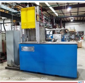
Figure 1. IQ system for processing gun barrels and long shafts
The IQ process is conducted in IQ water tanks (a batch IQ technique) and in single-part processing high-velocity water flow IQ units when parts are quenched one at a time. Steel parts are austenitized prior to intensive quenching in heat treating furnaces or using an induction through heating (ITH) method.2 As an example, Figures 1 and 2 present two production IQ systems. Each includes a single-part processing high-velocity water flow unit built by IQ Technologies. The IQ unit in Figure 1 is equipped with a single-shot low frequency ITH station built by Ajax TOCCO Magnethermic. It is designed for processing gun barrels and shafts of up to 36” long and up to 2” in diameter. The IQ unit in Figure 2 is equipped with a box atmosphere furnace and is designed for processing gear products of up to 8” in diameter and shafts of up to 15” long.
Figure 2. IQ system for processing gear products and shafts installed at Euclid Heat Treating Co.
Coupling of the single-part processing IQ technique with the ITH method (ITH + IQ) is the most effective way of IQ process implementation. It allows conducting of heat treating operations within a manufacturing cell in line with a steel parts production process. This paper focuses on two applications of the ITH + IQ process:
Elimination of a costly, energy and time-consuming carburization process
Substitution of a one-step ITH + IQ process for a two-step heat treatment consisting of batch quenching parts in oil or polymer for part core hardening followed by induction hardening
Elimination of Carburizing Process
The carburizing process is the most expensive and time-consuming heat treatment process. Elimination of the carburizing process by implementing the IQ method requires the use of limited hardenability (LH) steels. LH steels are medium to high carbon steels having exceptionally low content of alloy elements. When quenched intensively, LH steels provide a hard, martensitic case, tough, ductile core, and high residual surface compressive stress mimicking a carburized condition without carburization.
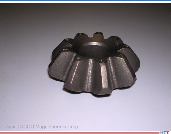
Figure 3. Side pinion
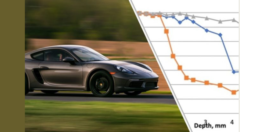
Two IQ case studies were conducted with two major U.S. automotive parts suppliers for evaluating the IQ process when applied to side pinions and drive pinions made of LH steel. Results obtained were compared to the same parts made of alloy steel, carburized and quenched in oil.
Side Pinions
Figure 3 presents a picture of the evaluated side pinion having the outside diameter (OD) of 80mm and inside diameter (ID) of 27mm. Standard pinions were made of alloy 8620 steel, carburized, quenched in oil, and shot peened. Pinions made of LH steel (acquired from Russia) were quenched intensively in the high-velocity water flow single-part processing IQ unit. The LH steel pinions were not shot peened after heat treatment. A chemical composition of the LH steel used is presented in Table 1.
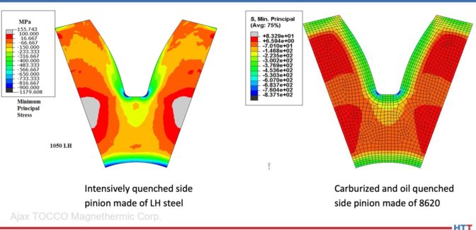
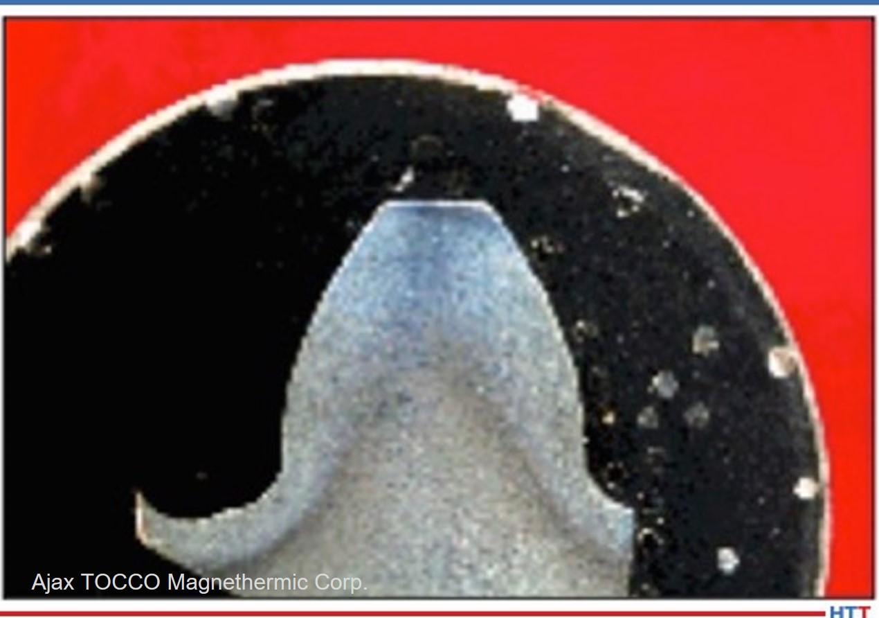
To evaluate the side pinion structural and stress conditions during heat treatment, DANTE computer simulations were conducted by DANTE Solutions, Inc. of Cleveland, Ohio, for standard carburized side pinions and for intensively quenched pinions made of LH steel.3 It was shown that the microstructure of the carburized and quenched-in-oil side pinion consists of martensite formed within the part carburized case and bainite in the remaining part cross section (Figure 4).
Figure 4. Microstructure distribution
Figure 5. Minimum principal stress
A microstructure distribution in the intensively quenched side pinion made of LH steel consists of a martensitic structure in the part surface layer, a bainitic structure beneath the martensitic case, and a perlitic structure in the part core. The martensitic case is generally deeper in the intensively quenched LH steel pinion compared to that of the standard pinion.
Figure 5 presents calculated values of the minimum principal stress that represent residual surface compressive stresses. As seen from the figure, the intensively quenched LH steel side pinion has residual surface compressive stresses greater than that of the carburized side pinion quenched in oil.
Figure 6. Experimental microhardness data for LH steel side pinion (PL – pitch line, RR – tooth root, TOT – tooth tip)
Figures 6–8 present experimental data obtained by the customer for the intensively quenched side pinions made of LH steel. Figure 6 shows hardness profiles at the pinion pitch line, tooth root, and tooth tip. Figure 7 presents an etched pinion tooth sample showing a martensitic case. As seen from the above figures, the IQ process provided the hard case and the ductile core that mimics a hardness distribution after carburizing.
Figure 7. Hardened case in intensively quenched side pinion made of LH steel
Figure 8 shows a residual surface compressive stress distribution for the LH steel side pinion root area. Residual surface compressive stresses for the intensively quenched side pinion made of LH steel were greater than that of the standard carburized and shot peened pinion. Fatigue testing has proven that intensively quenched side pinions made of LH steel have a longer service life compared to the standard pinions.
Figure 8. Residual stress distribution in intensively quenched side pinion made of LH steel
Drive Pinions
An IQ case study was conducted for drive pinions with one of the major U.S. automotive parts suppliers. Drive pinions were made of LH steel produced by a U.S. steel mill (the LH steel chemistry is proprietary information). Figure 9 presents a picture of the evaluated drive pinion. The drive pinions were quenched in the high-velocity water flow single-part processing IQ unit. Per customer evaluation, the hardness profile in the intensively quenched drive pinions made of LH steel mimics the hardness distribution in the standard carburized and oil quenched drive pinions, while the values of the residual surface compressive stresses are greater for the intensively quenched LH steel pinions compared to that of the standard drive pinions. (This information is also not presented in the paper due to its proprietary nature.)
Figure 9. Drive pinion
The intensively quenched drive pinions met all the customer’s metallurgical specifications and passed both the ultimate strength test and the fatigue test. It was shown that the part fatigue resistance improved by about 150% compared to that of standard carburized and quenched in oil drive pinions. In addition, distortion of the intensively quenched drive pinions is so low that no part straightening operations are required.
Application of the ITH + IQ process and LH steels for side pinions and drive gears will result in the following major benefits:
Less energy usage due to elimination of the long carburization process
Lower overall part costs
Cleaner parts and work environment due to use of water instead of quench oil or polymers
Lower work-in-process inventories and shortened lead times, due to possibility of running heat treat operations in part manufacturing cell
Substitution of One-Step Heat Treating Process for Two-Step Heat Treatment
A two-step heat-treating process consisting of batch quenching of parts in oil or polymer for core hardening, followed by induction hardening, is used in the industry for many steel products. This heat-treating process provides parts with a hard case and tough, ductile core that is similar to the carburizing process. A substitution of the ITH + IQ method for the two-step heat-treating process is another attractive possibility for steel part makers in reducing the part cost.
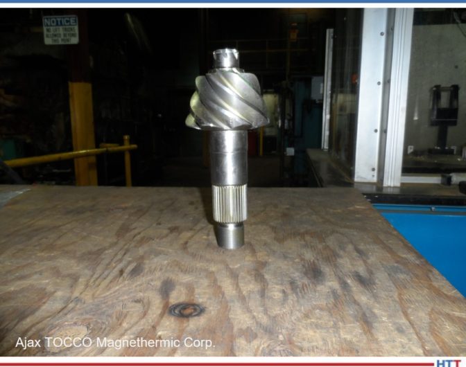
Figure 10. Typical input shaft
One of the major U.S. automotive parts suppliers applied this approach to the manufacturing of input shafts (Figure 10). The input shafts are currently made of high-alloy medium-carbon steel that requires annealing after forging. The intensively quenched input shafts were made of plain medium carbon steel that did not require annealing after forging. The shafts were quenched at the Ajax TOCCO Magnethermic Detroit Development & Support Center.
Per customer evaluation, the hardness profile in the intensively quenched input shafts was similar to that of standard shafts. Residual surface compressive stresses in the intensively quenched shafts are greater compared to that of the standard input shafts resulting in longer part fatigue life of up to 300%. (Per the customer’s request, the actual data on the part hardness profile, microstructure distribution, and values of residual surface compressive stresses are not presented in the paper.)
Figures 11 and 12 present current and improved input shaft production flow charts accordingly. As seen, an introduction of the ITH + IQ process allows elimination of the following input shaft manufacturing steps: annealing after forging, batch oil quenching, and shaft straightening. In addition, part shipping and material handling operations will be significantly reduced. In summary, the application of the ITH + IQ process provides the following major benefits in this case:
Less energy usage due to the elimination of two heat treating processes: annealing after forging and batch quenching in oil
Less material cost due to substitution of plain carbon steel for high alloy steel
Lower overall part costs due to the use of less expensive steel, reduction of heat treatment cost, elimination of all expenses associated with the use of quench oil, reduced cost of shipping and material handling, and elimination of part straightening operations
Cleaner parts and work environment due to use of water instead of quench oil or polymer
Lower work-in-process inventories and shortened lead times, due to possibility of running heat treat operations in part manufacturing cell
Figure 11. Drive pinion current production flow chart
Figure 12. Drive pinion improved production flow chart
Conclusion
Implementation of the ITH + IQ process and the use of LH steels will make possible the conducting of heat treat operations in a steel part manufacturing cell, reducing work-in-process inventories and shortening lead time. At the same time, tremendous energy savings, significant reduction of a carbon footprint, and overall part cost can be achieved due to eliminating the carburizing process and the use of quench oil, and due to the substitution of plain carbon steel for high alloy material. Improved work environment is also a bonus.
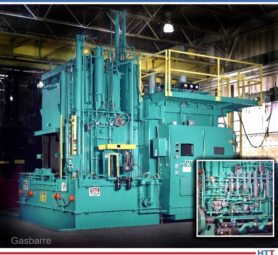
Figure 13a. IQ system for processing gear products and shafts Installed at Ajax TOCCO MagnethermicDetroit Development & Support Center
Figure 13b. IQ system for processing gear products and shafts Installed at Ajax TOCCO MagnethermicDetroit Development & Support Center
IQ Facility at Ajax TOCCO Magnethermic Detroit Development & Support Center
Ajax TOCCO Magnethermic has set up an IQ facility at its Detroit Development & Support Center (Figure 13). The facility includes a single-part processing IQ unit and an induction heating station. The IQ unit is capable of processing gear products, shafts, etc. of up to 8” in diameter and 15” long. The IQ unit controls monitor the following parameters: water temperature, water flow velocity, pump pressure, and dwell time. The induction heating fixture consists of a pneumatic horizontal indexing heat station used for power supply load matching and inductor positioning. The load matching station can be fed by numerous power supplies capable of various operating frequencies and power levels up to 600 kW.
The Detroit Development & Support Center also houses a large area for the manufacture and repair of induction tooling, along with engineers needed for the design of prototype and production tooling. There is also a metallurgical lab with the equipment and staff necessary to support the ITH + IQ process development. The metallurgical lab contains macro and micro hardness testers, cut-off wheels, polishing equipment and a metallograph for analyzing microstructures.
References
[1] N.I. Kobasko and N.I. Prokhorenko, “Quenching Cooling Rate Effect on Crack Formation of 45 Steel,” Metalloved. Term. Obrab., Met., No. 2, 1964, p. 53-54 (in Russian).
[2] M.A. Aronov, N.I. Kobasko, J.A. Powell, “Intensive Quenching of Steel Parts,” ASM Handbook, Volume 4A. Steel Heat Treating Fundamentals and Processes, 2013, p. 198-211.
[3] B.L. Ferguson, Zhichao Li, N.I. Kobasko, M.A. Aronov and J.A. Powell, “Limited Hardenability Steels and Intensive Quenching,” Proceedings of ASM Heat Treating Conference, Indianapolis, 2009.
About the Authors:Edward Rylicki is the vice president of Technology and Chris Pedder is the technical manager of Heat Treat Products and Services, at Ajax TOCCO Magnethermic Corp. For more information, contact info@ajaxtocco.com or 800.547.1527
Michael Aronov is the CEO at IQ Technologies, Inc. For more information, contact Michael at m.a.aronov@sbcglobal.com.
Your parts need heat treated to herculean surface hardness but with a soft, ductile core. That is to say, you are looking at case hardening processes, most likely one of these: gas carburizing, low-pressure carburizing, carbonitriding, gas nitriding, and ferritic nitrocarburizing.
Mike Harrison at Gasbarre Thermal Processing Systems brings us a Technical Tuesday article about what case hardening is and how five of the most common processes vary by (1) comparing the specific guidelines for each temp and time, (2) identifying equipment used to perform each process, and (3) providing a chart (at the end!) to understand different process considerations.
Mike Harrison Engineering Manager of Industrial Furnace Systems Division Gasbarre Thermal Processing Systems
Case hardening falls into a class of heat treatment processes that typically involve the addition of carbon and/or nitrogen to the material through solid-gas reactions at the surface followed by diffusion. These processes are performed for any number of reasons that generally include increasing strength and wear resistance, but in all cases the end result is a harder, higher-strength surface with a softer, more ductile core.
Case hardening processes can be divided into two subsets: those that include quenching to harden, such as gas carburizing, low-pressure carburizing (LPC), and carbonitriding; and those that do not include quenching, such as gas nitriding and ferritic nitrocarburizing (FNC). This article will provide a brief look into each process, the types of equipment used, and considerations for implementation.
Diffusion + Quenching Processes
These processes involve heating the workload to austenitizing temperature, which is above the upper critical temperature for the material in question, then supplying and allowing the desired element(s) to diffuse into the part surface, followed by rapid cooling (quenching) to create a phase change to martensite that strengthens the material. Tempering is then performed to create a material that has the desired final strength and ductility properties. The result is a high concentration of added elements on the surface that continually decreases through diffusion until eventually matching the same concentration as the base material; this gradient similarly produces a hardness that is higher at the surface, gradually diminishing until reaching the core. Higher alloyed steels may also see a microstructural change in the core from quenching that produces a core with higher hardness than the previously untreated material, but lower than the surface hardness produced.
Atmosphere Gas Carburizing
Gas carburizing is a process where carbon is added to the material’s surface. The process is typically performed between 1550-1750°F, with carburizing times commonly between 2-8 hours; of course, these values can vary depending on the material, process, and equipment. The most common atmosphere used for atmosphere gas carburizing is endothermic gas with additions of either natural gas or propane to increase the carbon potential of the furnace atmosphere. Common case depths achieved are around 0.005-0.040”, with deeper cases possible through a combination of longer treatment times and/or higher temperatures.
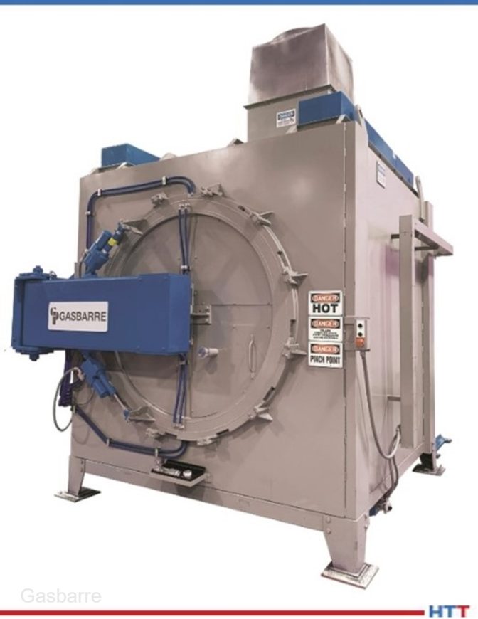
Fig. 1 – Integral quench furnace: "The atmosphere gas carburizing process can be performed both in batch and continuous equipment."
The atmosphere gas carburizing process can be performed both in batch and continuous equipment. On the batch side, traditionally an integral quench (IQ) furnace is used (Fig. 1); it consists of a heating chamber where the workload is heated and exposed to the carburizing atmosphere, then the workload is transferred to an attached quench tank for cooling. The entire furnace system is sealed and under protective atmosphere to preserve the part surface and maintain safe control of any combustible gases. For batches of large product, a pit furnace can be used for carburizing with the workload being transferred via an overhead crane into and out of the furnace to a quench tank.
For continuous processing, a belt furnace can be used. The product is placed on a belt and then progresses through the furnace at the desired temperature and atmosphere composition; the carburizing time can be varied by adjusting the belt speed through the furnace. At the end of the furnace, the parts drop off the belt into the quench tank. Then, a conveyor pulls the parts out of the tank and drops them on another belt to be washed and tempered. For continuous processing of heavier loads pusher furnaces, rotary retort, rotary hearth, and roller hearth furnaces can be used.
Fig. 2 – Endothermic gas generator: "To achieve a carburizing atmosphere endothermic gas is typically used, which is produced by an endothermic gas generator that heats a combination of natural gas and air to create a mixture that is approximately 40% hydrogen, 40% nitrogen, and 20% carbon monoxide."
To achieve a carburizing atmosphere endothermic gas is typically used, which is produced by an endothermic gas generator (Fig. 2) that heats a combination of natural gas and air to create a mixture that is approximately 40% hydrogen, 40% nitrogen, and 20% carbon monoxide. This mixture is generally considered carbon-neutral, meaning it will neither add nor deplete carbon from the surface. To increase the carbon concentration the endothermic gas needs to be enriched with a gas (typically natural gas or propane) that will help produce additional carbon monoxide, which will “boost” the carbon potential and drive carbon diffusion into the material.
A less common carburizing atmosphere comes from a nitrogen-methanol system, where nitrogen gas and liquid methanol are combined and injected into the furnace. Upon exposure to the high furnace temperature the methanol will decompose to hydrogen and carbon monoxide. Natural gas or propane additions are still required in order to provide carbon for absorption into the surface of the steel.
Low-Pressure Carburizing
Low-pressure carburizing (LPC), or vacuum carburizing, is a variation of carburizing performed in a vacuum furnace. Instead of the atmospheres mentioned previously, a partial pressure of hydrocarbon gas (such as propane or acetylene) is used that directly dissociates at the part surface to provide carbon for diffusion. After LPC, the workload is transferred to a quench system that could use oil or high-pressure gas, typically nitrogen. LPC with gas quenching can be an attractive option for distortion prone complex geometries as the cooling rates are slower than oil quenching; however, given the slower cooling rate, it becomes very important to choose a higher alloyed steel that will achieve the desired hardness.
Fig. 3 – Vacuum furnace with oil quench
LPC typically provides faster carburizing times when compared to traditional gas carburizing. This can be attributed to a more efficient reaction of the hydrocarbon gas used and to the option of using higher carburizing temperatures, typically up to 1900°F. This is made possible by the type of internal furnace construction of vacuum furnace design, although care must be taken at higher temperatures to avoid undesirable grain growth in the material. LPC also has the benefit of eliminating the potential for intergranular oxidation, since it is running in a vacuum system.
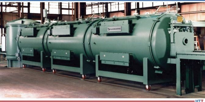
LPC is typically performed in a single-chamber vacuum furnace, with oil quenching or high-pressure gas quenching done in a separate chamber (Fig. 3). Continuous vacuum furnaces can also be used in applications that require increased throughput (Fig. 4).
Fig. 4 – Continuous vacuum furnace
Carbonitriding
Despite its name, carbonitriding is more closely related to carburizing than it is to nitriding. Carbonitriding is a process where both carbon and nitrogen are added to the material surface. This process is typically performed in a range of 1450-1600°F and generally produces a shallower case depth than carburizing. Carbonitriding is used instead of carburizing for plain carbon steels that do not contain enough alloying content to respond well to quenching, as the added nitrogen can provide a higher hardenability in the case to allow for proper hardness development.
Atmosphere carbonitriding can be performed in the same equipment as is used for carburizing. The furnace atmosphere is still typically endothermic gas-based and includes the addition of ammonia to provide the nitrogen. Vacuum carbonitriding with both hydrocarbon and ammonia additions can also be performed in the same equipment as used for vacuum hardening and low pressure carburizing.
Diffusion Only Processes
These processes involve heating the workload to a temperature below the austenitizing temperature, allowing the desired element(s) to diffuse into the part surface, then slow cooling. The increase in hardness at the material surface comes only from the addition of the diffused element(s), and not from a phase change due to quenching. As these processes are performed below the lower critical temperature (i.e., below the austenitizing range), the desired core hardness and microstructure need to be developed through a separate heat treatment prior to case hardening. Generally, the process temperature selected should be at least 50°F below any prior treatment temperatures to avoid impact to the core properties.
Gas Nitriding
Gas nitriding is a process where nitrogen is added to the material surface. The process is typically performed between 925-1050°F; cycle times can be quite long as the diffusion of the nitrogen is slow at these temperatures, with nitriding times typically ranging from 16 - 96 hours or more depending on the material and case depth required. Nitriding can be performed in either a single or two-stage process and has the potential to produce two types of case, the first being a nitrogen-rich compound layer (or “white layer”) at the surface that is extremely hard and wear-resistant but also very brittle. This compound layer depth is dependent on processing time. In the more traditional two-stage process, the case depth produces a gradient of hardness from surface to core that commonly ranges from 0.010-0.025”, with minimal white layer, typically between 0-0.0005”. Nitriding is typically performed on higher alloyed steels or steels specifically designed for the nitriding process (e.g., Nitralloy®) as it relies on the formation of nitrides to create the increased hardness, which is achieved through the use of nitride-forming alloys such as aluminum, molybdenum and chromium. Pre and post oxidation treatments can be incorporated into the cycle to achieve certain benefits. Since the process does not require quenching to harden, it has the potential of producing a product that is more dimensionally stable and may not require any post-process finishing.
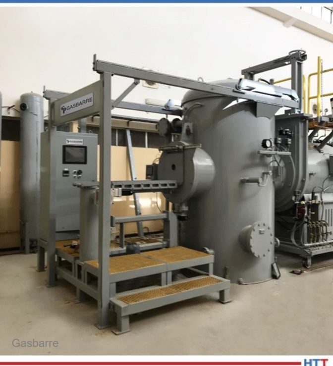
Fig. 5 – Horizontal retort nitriding furnace: "Traditionally, pit furnaces have been used for nitriding as they can accommodate larger load sizes and can be easier to seal as gravity helps keep the lid sealed; however, horizontal designs have gained in popularity in recent years."
This process is most commonly performed in batch equipment; while it is possible to use a continuous furnace, keeping the ends of furnace sealed to contain the atmosphere can be challenging. Traditionally, pit furnaces have been used for nitriding as they can accommodate larger load sizes and can be easier to seal as gravity helps keep the lid sealed; however, horizontal designs have gained in popularity in recent years (Fig. 5). In either case, the furnaces are usually a single-chamber design with the load sealed inside an Inconel or stainless steel retort.
To achieve a nitriding atmosphere, ammonia (not nitrogen) is used to supply the atomic nitrogen necessary for diffusion. At the process temperatures used, ammonia does not readily dissociate on its own; rather, it dissociates when exposed to a heated steel surface (iron acting as a catalyst) into atomic nitrogen and hydrogen. To control the amount of nitrogen available for nitriding, the dissociation rate of the ammonia can be measured with high dissociation rates (high hydrogen content) providing a lower nitriding potential and low dissociation rates (low hydrogen content) leading to more nitriding potential. The depth of the compound layer can be varied through control of the nitriding potential, with higher nitriding potentials producing a thicker compound layer.
For more precise atmosphere control, an ammonia dissociator can be used to provide gas to the furnace that has already been split to dilute the atmosphere with hydrogen to more quickly achieve a high dissociation rate in the furnace. The ammonia dissociator is a heated box with a small retort inside; the ammonia is passed through this retort that contains a catalyst to promote the dissociation of the ammonia, and the resulting gas mixture is cooled and then injected into the furnace.
Ferritic Nitrocarburizing
In the author’s opinion, just like with carbonitriding, ferritic nitrocarburizing (FNC) is named incorrectly as it is more closely related to nitriding than it is with carburizing. FNC is a process that is still mostly nitrogen-based but with a slight carbon addition as well. The added carbon helps promote compound layer formation, particularly in plain carbon and low alloy steels that do not contain significant nitride-forming alloys. This process is typically performed in a range of 1025-1125°F with cycle times much shorter than nitriding, typically 1-4 hours. The compound layer produced is usually much deeper than nitriding at 0.0005-0.0012”, with case depths reaching up to 0.025”, although in many applications a case depth may be difficult to measure. FNC is usually performed instead of nitriding in applications where the deeper compound layer is needed to increase wear resistance, but the added strength of a deep case depth is not as critical.
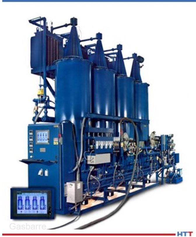
FNC can be performed in the same equipment used for nitriding, as long as a hydrocarbon gas is available to the furnace such as carbon dioxide or endothermic gas. FNC can also be performed in an IQ furnace using a mixture of ammonia and endothermic gas; for cooling, the parts can be oil quenched or slow cooled in a top cool chamber (if equipped).
Considerations
Case hardening processes are some of the most common heat treatments performed, but each process has its own unique needs. The table below provides a summary of the considerations that need to be made when selecting the optimum process. This list is by no means exhaustive; it is encouraged to work with a furnace manufacturer familiar with each process to help select the correct process and equipment needed.
About the Author: Mike Harrison is the engineering manager of the Industrial Furnace Systems division at Gasbarre. Mike has a materials science and engineering degree from the University of Michigan and received his M.B.A. from Walsh College. Prior to joining Gasbarre, Mike had roles in metallurgy, quality, and management at both captive and commercial heat treat facilities, gaining nearly 20 years of experience in the thermal processing industry. Gasbarre provides thermal processing equipment solutions for both atmosphere and vacuum furnace applications, as well as associated auxiliary equipment and aftermarket parts & service.
For more information: Contact Mike at mharrison@gasbarre.com
Brazilian commercial heat treater Tecnovacum recently received a vacuum furnace, produced in cooperation between a Polish-based furnace suppler and a Brazilian-based furnace manufacturer.
For the first time in the history of the SECO/WARWICK Group, parent company to North American SECO/VACUUM Technologies, the order was executed in a 50/50 cooperation system – Tecnovacum’s financing plan with an industry development bank stipulated that at least 50% of the equipment production would be in Brazil with Combustol Fornos Ind Com. Ltda, who was the partner for this project.
Maciej Korecki Vice President of the Vacuum Furnace Segment SECO/WARWICK (source: SECO/WARWICK)
The Vector vacuum furnace is the first product that the supplier has provided to Tecnovacum. To implement the government subsidy program, the equipment must have 50% of the production in the territory of Brazil. The furnace was developed in close cooperation with the Brazilian partner – Combustol Fornos Ind Com. Ltda. Cooperation between the two companies has been ongoing for six years in terms of sales, supplies and start-ups of furnaces in Brazil.
"This is an exceptional situation, the first one, but certainly not the last," commented Maciej Korecki, vice-president of the Vacuum Segment of the SECO/WARWICK Group. "Under our supervision and in close cooperation, the Brazilian partner made the casing and the control cabinet in Brazil, and the company was also responsible for the equipment assembly and start-up [. . .] We are glad that we have a partner who is not only able to carry out the assembly, start-up and service of our equipment on site, but also build the entire vacuum furnace in cooperation with us."
A Michigan-based captive heat treater in the precision automotive and specialty fastener industry will receive a 6000 lb/hr continuous mesh belt furnace to complete its new line.
Can-Eng Furnaces International, the provider of the furnace, utilized their Level 2 Automation to enable the heat treater to track product status, diagnose equipment, and provide process data. The system will lower the heat treater’s energy requirements for the hardening furnace and reduce required atmosphere by one-third. The system is equipped with an automated bin-dumping loader, pre-washer, atmosphere-controlled mesh belt hardening system, oil quench, post wash system, temper furnace, in-line soluble oil system, and bi-directional conveyor discharge.
For Ovako, a centuries old manufacturer of engineering steel, innovative approaches to producing their product has taken the form of electrifying their roller hearth furnaces over the course of the past decade.
The process of converting to electric heating began in 2014, each furnace installed with up to 86 Tubothal® metallic heating elements from Kanthal. Now, 14 roller hearth furnaces are electrified. The estimated CO2 savings is around 1,400 to 2,000 tons per year per furnace.
“[In] our heat treatment shop in Hofors,” shares Anders Lugnet, a furnace technology specialist at Ovako (pictured above), “we originally had around 450 gas burners, and there was always a problem somewhere in one of them. Since replacing them with 300-odd Tubothal® elements, the daily maintenance is simply not there. Occasionally, an element needs to be replaced, but it is nothing compared to the way it was.”
He continues that, previously, NOx and CO2 emissions were problematic. But with green electricity, emissions are zero, and with no flue-gas losses, total efficiency has improved significantly.
Today's shared content is provided by the global information partnership between leading European heat treat news provider heatprocessing and the team at Heat TreatToday.
It may be starting in Europe, but through "free and fair-trade", increasing aluminum use may find its way around the world. On September 28th and 29th, engineers and business advocates gathered at the ALUMINUM Business Summit to discuss mobility, digitization, sustainability, and the market development of steel. This article, written by Dr. Gerd Götz, Director General at European Aluminium, is a preview to the discussions that took place.
An excerpt:
"Aluminium is a sustainable material essential to Europe’s green transition. It is used in solar panels, wind turbines, electric vehicles, transmission cables for renewable electricity, etc. The endless recyclability of aluminium further contributes to decarbonization and the circular economy."


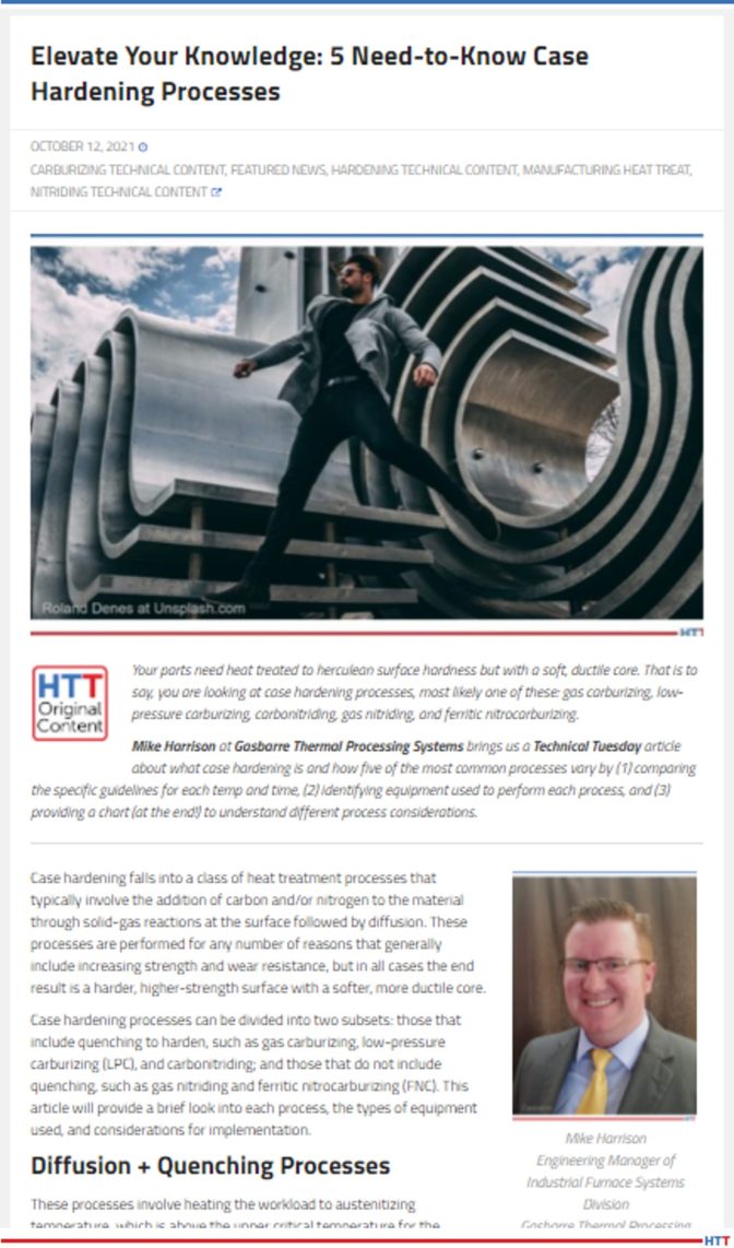
 Recently, SECO/WARWICK shared their nitriding technological developments in their product, ZeroFlow.