When the new additive research facility at the Oregon Manufacturing Innovation Center Research & Development (OMIC R&D) opens in Scappoose, Oregon, the facility will acquire a hot isostatic press. Operating at a temperature of 2550°F (1400°C) and a pressure of up to 30,000 psi (2070 bar), the new press will give OMIC researchers the ability to study densification of metals as well as how HPHT can modify the grain structure to enhance the mechanical properties of additively manufactured parts.
Overseen by Oregon Institute of Technology (Oregon Tech), a public polytechnic university, OMIC R&D is a collaborative effort that brings together industry and higher education with government support to conduct applied research and advanced technical training. Its mission is to increase industrial competitiveness by developing new tools and techniques to address today’s manufacturing challenges, particularly in the aerospace and defense, transportation, and metals sectors.
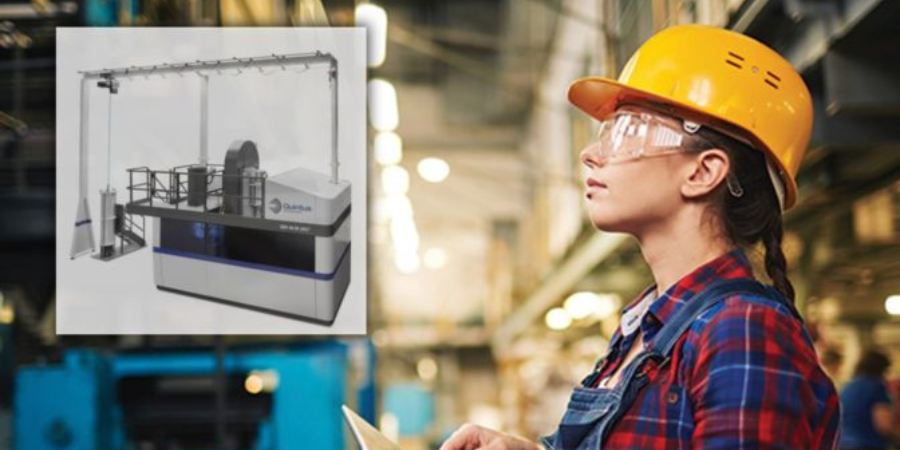
The Quintus TechnologiesHIP, a QIH 48 M URC® press, will allow new research into 3D printing technology and optimized material properties. The press model is equipped with Uniform Rapid Cooling, URC®, the proprietary Quintus feature that combines HIP and heat treatment in a single process. Accelerated cooling under pressure minimizes thermal distortion and improves material properties. The QIH 48 also has a hot zone of 14.8 inches (375 mm) in diameter and 47.2 inches (1200 mm) in height.
“For OMIC R&D to fulfill our mission, we must have world-class cutting-edge capabilities to support our applied research & development projects. We accomplish this by partnering with some of the best companies in the world in their respective fields and identifying and utilizing their unique technologies and expertise. Our solutions can be implemented by regional, national, and international partners to increase their competitiveness,” says Craig Campbell, executive director at OMIC. “We chose Quintus as a partner because the company is continually innovating, and developing new processes such as High Pressure Heat Treatment, or HPHT.”
The press will be housed in OMIC’s new 30,000-square-foot additive manufacturing innovation center in Scappoose, approximately 20 miles north of Portland. Scheduled for ground-breaking in late 2021 and occupancy in 2022, the facility will be adjacent to the Portland Community College/OMIC Training Center, which serves students in machining, fabrication, and mechatronics.
“Today’s globally competitive manufacturing industry demands rapid innovations in advanced manufacturing technologies to produce complex, high-performance products at low cost,” observes Dr. Mostafa Saber, associate professor of Manufacturing & Mechanical Engineering Technology at Oregon Tech. “To conduct world-class, competitive research on new high-performance metal alloys, long-lasting tools, and rapid production of complex metal structures, especially in additive manufacturing, materials densification plays a pivotal role. And that is where the advanced generation of hot isostatic pressing offers the solution. We are very excited to leverage the advantageous features offered by Quintus Technologies soon at OMIC R&D.”
Burloak Technologies recently received and commissioned two furnace systems for use in both R&D as well as full-scale additive manufacturing production of aluminum products. Burloak reported that parts initially being processed in the two furnace systems included items for the Canadian Space Agency and revolutionary communications satellites.
The two furnace systems, from DELTA H, include a single-chamber (SCAHT®), fully-automated, horizontal quench, solution heat treating furnace capable of operating from ambient to 1200°F followed by rapid quenching in less than seven (7) seconds – a requirement for processing critical-application aluminum parts. This SCAHT® furnace is also capable of slow quenching geometrically complex AM parts. The systems provide precise duplication of heat treat cycles. Included is a comprehensive data acquisition system in full compliance with AMS2750F - Instrumentation Types A, B, or C and can produce irrefutable, scientifically defensible batch records.
Peter Adams Founder and Chief Innovation Officer Burloak
"DELTA H builds straightforward, easy to use heat treatment ovens that are exceeding our internal and customer quality requirements. Training personnel from operations, maintenance and quality is an easy and painless process. The transparency of the systems will be pleasing to customer, AS9100 and Nadcap auditors," said Peter Adams, Burloak Technologies chief innovation officer and co-founder.
Ellen Conway Merrill Vice President DELTA H TECHNOLOGIES, LLC
Ellen Conway Merrill
"The systems provided to Burloak represent a new chapter in our dedication to the aviation and aerospace industries as well as additive manufacturing in general, explains DELTA H's vice president Ellen Conway Merrill. "It is very humbling to be among the technology providers to such an innovative and pioneering company as Burloak Technologies."
Burloak also commissioned a dual chamber (DCAHT®) aluminum aging oven system.
Michael Lister Director of Sales - North America Consarc Corporation
The Doncasters Group recently ordered a vacuum furnace for their Doncasters Southern Tool facility in Oxford, Alabama. The order includes startup and installation with delivery scheduled before the end of 2021.
The new 300-pound Consarc vacuum precision investment casting (VPIC) furnace is equipped with high vacuum capabilities, controls, and increased automation with Teach Pour and other features that will give this furnace exceptionally high productivity for Doncasters Group.
The company is an international manufacturer of high-precision engineering components, designed to operate in the most demanding conditions. They serve the world’s leading OEMs in the aerospace, industrial gas turbine, and specialist automotive markets.
This order represents the 16th VPIC ordered from Consarc for delivery in North America in the last 24 months. Globally, the supplier has received 30 orders for this type of equipment in the same time frame.
"The recent strength in obtaining new orders for this product line is a testament to a customer centric philosophy we have at Consarc," said Michael Lister, director of Sales – North America at Consarc Corporation. "Our clients are sophisticated process owners who are well versed in the equipment and have demanding specifications placed on them by their own customers. Our collaborative approach in design, both before and after the order, is why customers trust [us] with these high value projects. We are able to understand their current problems and engineer long term solutions to mitigate those issues."
"A compressive surface stress can benefit bend fatigue performance by reducing the mean stress experienced during service, effectively offsetting the tensile stress generated by the cyclic loading conditions." In this Technical Tuesday by Justin Sims of DANTE Solutions, learn how a simulation program, funded by the U.S. Army, modeled the method of Intensive Quenching®.
This article covers Phase 2 of the project, a follow up to an article that was previously featured on Heat TreatToday. Check out more original content articles in this digital edition or other editions here.
Justin Sims Lead Engineer DANTE Solutions
Helicopter powertrain gearing can be subjected to tremendous loads during service. The high tensile loads experienced in the root of the gear tooth, combined with the cyclic loading conditions inherent in gear operation, can lead to cyclic bend fatigue failures. To improve cyclic bend fatigue performance, low alloy steels are often carburized and quenched. The combination of a high carbon case and low carbon core leads to increased strength and hardness in the carburized case, while maintaining a tough core. In this manner, the case resists wear and can carry a high load without fracture, while the core is able to absorb the energy imparted to it during operation. Besides the increased strength and hardness, the addition of carbon creates a chemical gradient from the surface of the component towards the core. The carbon gradient creates delayed martensite transformations, relative to the low carbon in the core, and is responsible for imparting residual compressive surface stress. A compressive surface stress can benefit bend fatigue performance by reducing the mean stress experienced during service, effectively offsetting the tensile stress generated by the cyclic loading condition
Since the timing of the transformation to martensite is the main driver in the generation of compressive residual surface stresses, it is possible, to some extent, to control the magnitude of the surface stress by changing the quenching process. Historically, transmission gears have been carburized and quenched in oil. However, as more and more attention is paid to improving part performance through processing techniques, other forms of quenching have become available that show promise in increasing surface compressive stresses, and thereby improving bend fatigue performance. Of particular interest, is a quenching method which utilizes high pressure, high velocity water to quench parts.
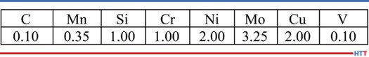
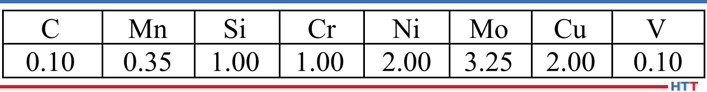
Table 1. Pyrowear 53 nominal chemistry.
Known as Intensive Quenching®, the method was developed by Dr. Nikolai Kobasko as an alternative means of quenching components to achieve deep residual surface compression and improve bend fatigue performance.1–3
The technology works by inducing a large temperature gradient from the surface to the core of the component. In non-carburized components, the process has been shown to provide an extremely rapid and uniform transformation to martensite in the surface layers, while the core remains austenitic. This creates a hard shell, under extreme compression. As the part continues to cool, the surface is pulled into an even deeper state of compression. As the core transforms, some compression is lost due to the expanding core, but the compression that remains is generally greater than that achieved by oil quenching.4–7
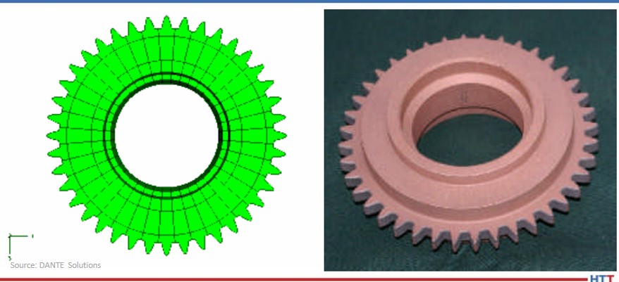
Figure 1. Gear CAD model (left) and actual test gear (right).
To evaluate the possibility of improving bend fatigue of helicopter transmission gears, a program was conceived to compare the bend fatigue performance of carburized gears quenched in oil versus carburized gears quenched using the Intensive Quenching process. Funded by the US Army, the project was comprised of two phases. Phase 1, described in a previous Heat Treat Today article, was a proof-of-concept phase, designed to prove that intensively quenched components could outperform oil quenched components in high cycle bend fatigue testing. Phase 2 then moved to actual transmission gear testing. DANTE heat treatment simulation was used extensively throughout the project to guide processing decisions and understand the mechanisms responsible for improved bend fatigue performance though the creation of residual surface compression. This article will examine Phase 2 of the project.
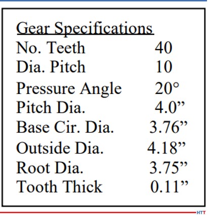
Table 2. Test gear specifications.
Pyrowear 53 was the material of choice for the project, as it is used extensively in helicopter power transmission gearing. Table 1 lists the nominal alloy chemistry for Pyrowear 53, which is a low-carbon, carburizing grade of steel. Figure 1 shows a CAD model of the test gear (left) and a picture of an actual test gear (right); the actual test gear is copper plated to selectively carburize only the gear teeth. The gears were carburized as one batch, and then hardened and tempered to a tooth surface hardness of 59 HRC and a core hardness of 42 HRC. An oil quenching process was used to harden half of the gears and an Intensive Quenching process was used to harden the other half of the gears. Table 2 lists the dimensional specifications of the gear.
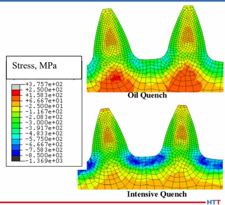
One benefit of using the Intensive Quenching process over a conventional oil quenching process is the development of high residual surface compression. Compressive surface stresses benefit fatigue performance by offsetting any tensile stress generated during loading, effectively reducing, or eliminating, the tensile load experienced by the material. Figure 2 compares the residual stress predicted by DANTE for the test gear subjected to an oil quenching process (top) and an Intensive Quenching process (bottom). It is clear that the Intensive Quenching process induces a greater magnitude of compression in the area of the tooth root, which is the location of most gear bending fatigue failures. The residual stresses present in the tooth flank appear equivalent between the two quenching processes, but the oil quenched component has higher tensile stresses under the carbon case. This could lead to problems should any inclusions or material defects be present in that location.
Figure 2. Residual stress prediction for test gear, comparing oil quench and Intensive Quench.
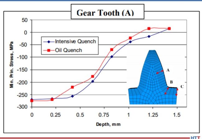
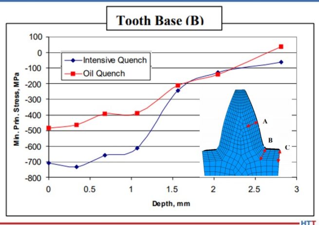
Figures 3 – 5 compare the residual stress profiles of the two gears at three gear tooth locations: flank, root-fillet, and root, respectively. The residual stress profiles for the two processes at the tooth flank, shown in Figure 3, are equivalent, as inferred from the contour plots shown in Figure 2. Both quenching processes generate a surface compressive stress of 275 MPa on the tooth flank. However, the residual stress profiles in the root area of the gear vary greatly between the two processes. Figure 4 shows the residual stress profile at the root-fillet, which is the location of the highest tensile stress during gear service. At this location, the rapid surface cooling afforded by the Intensive Quenching processes creates a large temperature gradient from the surface to the core, allowing more thermal shrinkage to occur after the surface transforms to martensite. The additional thermal shrinkage, combined with the concave geometry of the gear root area, creates additional compressive stresses in this area.
Figure 3. Residual stress versus depth prediction for test gear at point A, comparing oil quench and Intensive Quench.
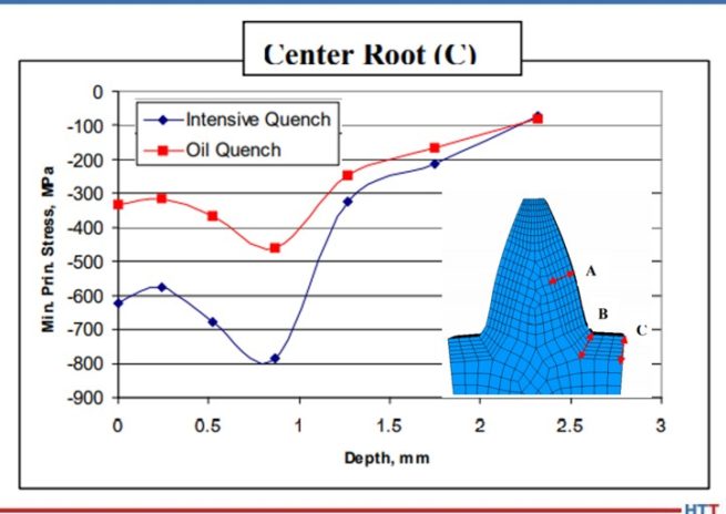
Figure 4 shows that the Intensive Quenching process generated a compressive stress of 700 MPa on the surface of the root-fillet, while the oil quenched gear produced a 500 MPa compressive surface stress in this location. The intensively quenched gear also has a deeper layer of high compression, not rising above 600 MPa compression until after 1 mm below the surface. Figure 5 shows a similar trend for the root, but with an even larger difference between the two quenching processes, since the geometry is even more concave at this location. Again, the gear subjected to the Intensive Quenching process has high compression up to 1 mm under the surface and a compressive surface stress magnitude 300 MPa higher than the oil quenched gear at the root location. The modeling results indicate that the intensively quenched gears should outperform the oil quenched gears in bend fatigue given the increased surface compressive stress present.
Figure 4. Residual stress versus depth prediction for test gear at point B, comparing oil quench and Intensive Quench.
Figure 5. Residual stress versus depth prediction for test gear at point C, comparing oil quench and Intensive Quench.
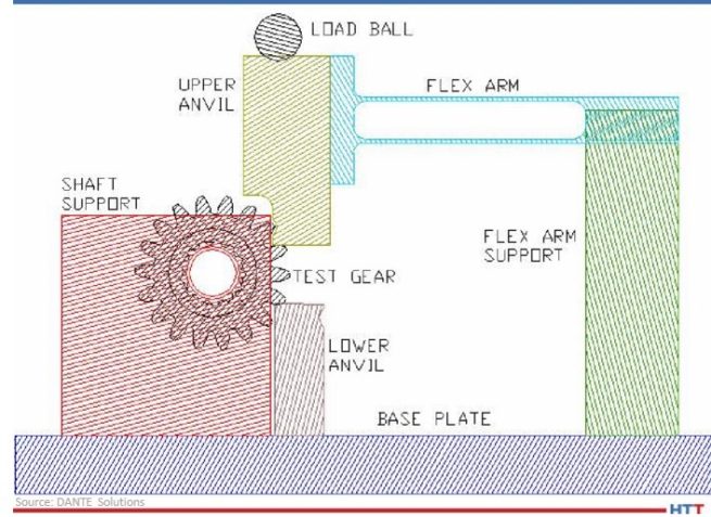
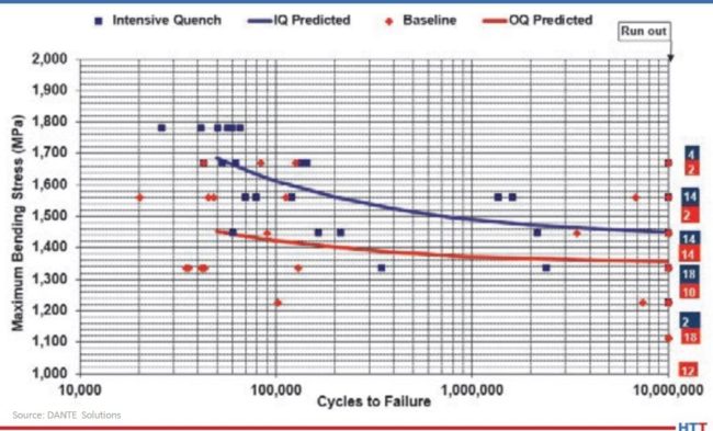
All of the hardened gears were tested at the Gear Research Institute, located at Pennsylvania State University in State College, PA, using a servo-hydraulic testing machine with a specially designed fixture to apply a cyclic bending load to two teeth. A schematic of the fixture is shown in Figure 6. A load ratio of 0.1 was used for all fatigue tests to ensure the gear did not slip during testing by having a constant tensile load applied. The fatigue test was considered successful, defined as a runout, if the gear completed 107 cycles given a certain maximum load. The maximum bending stress, calculated for a stress-free initial condition, was used to compare the two processes.
Figure 6. Schematic of fatigue testing apparatus.
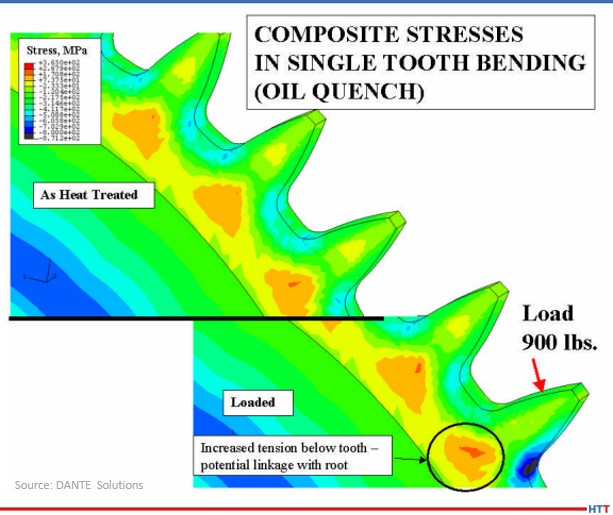
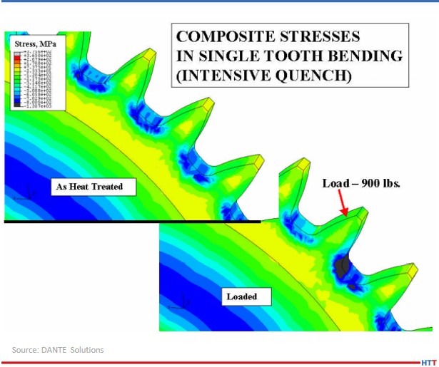
As previously mentioned, the effect of residual compressive stresses during tensile bend fatigue is to offset the tensile stress generated by the load. Figure 7 shows a DANTE model of the test gear subjected to oil quenching showing the residual stress from heat treatment (top) and the stress redistribution during the application of a 900 lb. load (bottom). Figure 8 shows the same conditions for the test gear subjected to the Intensive Quenching process. As can be seen from the two figures, in which the legend ranges are the same, there is substantially more compressive stress remaining in the root-fillet area of the gear subjected to the Intensive Quenching process when the load is applied. This means the effective stress experienced by the intensively quenched gear is less than that of the oil quenched gear, given an identical load.
Figure 7. Stress predictions for the oil quenched gear, showing the residual stress from heat treatment (top) and the stress change when a 900 lb. load is applied (bottom).
Figure 8. Stress predictions for the Intensive Quenched gear, showing the residual stress from heat treatment (top) and the stress change when a 900 lb. load is applied (bottom).
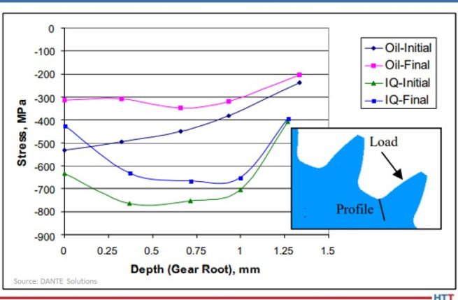
Figure 9 shows the residual stress profile from the surface at the root-fillet for both processes, in the unloaded and loaded conditions. From the plot, a load of 900 lb. generates a tensile stress of approximately 200 MPa, which is offset by the compressive residual stresses. With a 900 lb. load, neither gear sees any tensile stresses during loading, and thus, should runout during fatigue testing.
Figure 9. Comparison of predicted stresses versus depth for the oil quench and Intensive Quench gears in the unloaded (Initial) and loaded (Final) state.
Figure 10 shows the results of the fatigue testing. As expected, the gears subjected to the Intensive Quenching process have an increase in fatigue performance. The endurance limit of the intensively quenched gears is approximately equal to the difference in surface compression, though additional tests should be conducted to confirm this. Regardless, increasing the magnitude of surface compression through a process change can significantly improve fatigue performance of power transmission gearing.
Figure 10. S-N curves for the oil quench and Intensive Quench gears tested.
In conclusion, achieving higher residual surface compressive stresses during hardening of a carburized power transmission gear by way of a process change was shown to improve bend fatigue performance. This was confirmed by the company's simulations, which showed a significant increase in compressive surface and near-surface stresses when the gear was quenched using the Intensive Quenching process, as opposed to an oil quench. The cause of the increased compression was determined from simulations to be due to the combination of martensite formation in the surface layers of the gear and the accompanying thermal shrinkage of the austenitic core, which draws concave geometric features, such as a gear tooth root, into a higher state of compression. The large temperature gradient induced during the Intensive Quenching process is necessary to produce these conditions. Physical fatigue testing confirmed the simulation results, showing a significant improvement in fatigue performance for the gears quenched using the Intensive Quenching process. Accurate process simulation pointed to a heat treatment process change that could be used to achieve increased power density through a transmission as opposed to more expensive and time-consuming design changes.
N. I. Kobasko and V. S. Morganyuk, “Numerical Study of Phase Changes, Current and Residual Stresses in Quenching Parts of Complex Configuration,” Proceedings of the 4th International Congress on Heat Treatment of Materials, Berlin, Germany, 1 (1985), 465-486.
N. I. Kobasko, “Intensive Steel Quenching Methods. Theory and Technology of Quenching”, SpringerVerlag, New York, N.Y., 1992, 367-389.
N. I. Kobasko, “Method of Overcoming Self Deformation and Cracking During Quenching of Metal Parts,” Metallovedenie and Termicheskay Obrabotka Metallov (in Russian), 4 (1975), 12-16.
M. Hernandez et al., Residual Stress Measurements in Forced Convective Quenched Steel Bars by Means of Neutron Diffraction”, Proceedings of the 2nd International Conference on Quenching and the Control of Distortion, ASM, (1996), 203-214.
M. A. Aronov, N. I. Kobasko, J. A. Powell, J. F. Wallace, and D. Schwam, “Practical Application of the Intensive Quenching Technology for Steel Parts,” Industrial Heating Magazine, April 1999, 59-63.
A. M. Freborg, B. L. Ferguson, M. A. Aronov, N. I. Kobasko, and J. A. Powell, Intensive Quenching Theory and Application for Imparting High Residual Surface Compressive Stresses in Pressure Vessel Components,” Journal of Pressure Vessel Technology, 125 (2003), 188-194.
B. L. Ferguson, A. M. Freborg, and G. J. Petrus, “Comparison of Quenching Processes for Hardening a Coil Spring,” Advances in Surface Engineering, Metallurgy, Finishing and Wear, SAE (01) 1373, (2002).
About the Author: Justin Sims has been with DANTE Solutions for eight years and is an excellent analyst and expert modeler of steel heat treat processes using the company's software. His project work includes development, execution, and analysis of carburization, nitriding, and quench hardening simulations. For more information, contact Justin at justin.sims@dante-solutions.com.
Fives, an international industrial engineering group for silicon steel processing lines, will receive high efficiency burners with low emissions. This will help the company as they fulfill recent orders involving the supply of annealing and pickling lines as well as annealing and coating lines to Chinese steelmakers.
The burners were designed and supplied by WS Wärmeprozesstechnik, and with their FLOX® process, Fives will be able to manufacture using the strictest emission values without SCR (selective catalytic reduction) treatment for their furnaces for silicon steel. This was necessary as China’s steelmakers have been demanding combustion technology with lowest NOx emissions in order to meet climate-related goals.
Dr.-Ing. Joachim G. Wünning President WS Wärmeprozesstechnik GmbH
The silicon strip line with FLOX® burners from WS (pictured above) will assist Fives in their current orders as well as their continued design and supply of machines, process equipment, and production lines in various sectors. These sectors include steel, aerospace and special machining, aluminum, automotive and manufacturing industries, cement, energy, logistics and glass.
"It is our ambition at WS," states Dr.-Ing Joaching G. Wünning, president of WS Wärmeprozesstechnik GmbH, "to provide solutions for all continuously operated strip lines which can reliably attain NOx emissions well below 100 mg/Nm³, with simultaneously high combustion efficiency over 80% and which are, already today, suited for a future with green combustion gases."
A Canadian leader in the coating industry will expand their heat treat capabilities with a floor-standing box furnace used for ceramic coating applications for parts in the aerospace industry.
The L&L Special Furnace Company Inc. model XLE214 is used for curing and bonding ceramic coatings to various steel bodies. This process provides extra strength to aerospace parts that are subject to various heats and stresses under normal operating conditions.
The furnace has an effective work zone of 22" wide by 16" high by 20" deep. A horizontal door with ceramic hearth and support bricks is included to incorporate the customer’s loading system. Nickle chrome elements are used in the furnace that are resistant to any potential contamination the process may cause. Heat shields provide a safe-to-touch case temperature under operating conditions.
Model XLE MDS from L&L Special Furnace Company, Inc.
The model XLE214 is controlled by a Eurotherm program control with overtemperature protection, chart recorder with jack panel, solid-state relays, and zone controls for balance of temperature gradients. Thermocouples, fusing and electrical interconnections are included. The furnace control circuit is completely tested to ensure proper operation prior to shipping.
The furnace case is sealed for use with inert atmosphere to help reduce oxygen impregnation with the parts. The furnace has a manual inert flow panel to control the inert gas flow into the oven.
The model XLE214 also includes a high-convection fan for uniformity of ±10°F/5.5°C above 500°F/260°C to 1,875°F/1,023°C. There is a 4" diameter venturi with a variable frequency drive to evacuate outgassing that occurs during the curing of the ceramics to the steel part. The system is completely automated through the program control logic.
Spanish regional airline Air Nostrum L.A.M. S.A. has selected StandardAero to provide support services for the Pratt & Whitney PW127M engines powering its fleet of ATR 72-600 regional turboprops. Under the five-year agreement, StandardAero will provide PW127M hot section inspections (HSIs) and additional services from its OEM-authorized PW100 Designated Overhaul Facilities (DOFs) in Gonesse, France and Summerside, PE, Canada.
Air Nostrum has also renewed its selection of StandardAero as the exclusive support provider for the Honeywell GTCP36-150RJ and RE220[RJ] auxiliary power units (APUs) equipping the airline’s fleet of CRJ200 and CRJ900/1000 regional jets. Under these contract renewals, StandardAero will continue providing Air Nostrum with a range of services for the GTCP36-150RJ and RE220[RJ] from its Maryville, TN location, which is a Honeywell-approved Authorized Service Center for the APUs.
Lewis Prebble President of Airlines and Fleets StandardAero
"Against the backdrop of the current COVID-19 situation, which has significantly affected the aviation sector," said Fermín Tirado, managing director of ANEM, the new engineering and maintenance subsidiary of Air Nostrum, "it is very important to have a reliable and consistent partner delivering a competitive cost and maintaining our engines to run at peak efficiency, which contributes to reduced CO2 emissions."
"We are proud to have been entrusted by Air Nostrum for the support of their PW127M, RE220 (RJ) and GTCP36-150RJ fleets," commented Lewis Prebble, president of Airlines and Fleets for StandardAero. "We are dedicated to supporting Air Nostrum and its passengers, and look forward to continuing our close relationship for many years to come."
StandardAero is a Designated Overhaul Facility (DOF) for the P&W PW100 family, with overhaul facility locations in Summerside, PE, Canada and Gonesse, France, supported by five service center locations across the Americas, Europe, Africa and Asia.
Indian manufacturer in the defense and aviation sector TATA Advanced System Ltd. (TASL) will receive a solution heat treatment line. It is dedicated for the aviation industry and will meet the requirements of the latest aviation (AMS2750F) and material (AMS2770) standards.
This order, the third of its type from North American manufacturing parent company SECO/WARWICK to TASL, will be the largest production line for aircraft skins in the history of both companies. The equipment will be used for the production of aircraft skins, empennage and center-wings boxes. The line includes a rapid quench VertiQuench® electric furnace (drop-bottom type), mobile quenching tank, rinsing tank and additional equipment including a chiller and loading baskets.
Piotr Skarbiński Vice President of the Aluminum Process and CAB Business Segments SECO/WARWICK Group Source: SECO/WARWICK
The working zone of the furnace is L7500 x W3000 x H3000mm, with the capacity to process huge sheets of aluminum. Such a large working zone reduces the number of joints in the skin. The line, as designed, will meet the client's requirements, ensuring a guaranteed +/- 5°C load temperature uniformity, load cooling in either a polymer or a water quench, and will remove the polymer sediment remaining after quench. Additionally, the system can be used for artificial aging in the furnace.
Abhishek Paul, manager and head of supply chain management of TASL said, "The new line, apart from its size, will meet a number of guidelines that will allow us to produce the highest quality airplane components that will meet the expectations of our final customers - a vast portfolio of OEMs and Tier-1s in the aerospace and defense industry. We are also confident that [the company] will be able to meet the project timelines and handover the line well within our project timelines."
"For us," explains Piotr Skarbiński, vice president of the aluminum process and CAB business segments at the SECO/WARWICK Group, "this continued cooperation directly means that the client is satisfied with the quality and efficiency of [our] equipment, services and our partnership. We hope that this partnership will continue into the future."
What do helicopter gears and heat treat modeling have to do with improving the bend fatigue performance of low-alloy gear steels? Find the answer in this interesting case study which analyzes the effects on compressive surface stress caused by changing the heat treating process.
This Technical Tuesday is provided by Justin Sims of DANTE Solutions and was featured in the Heat TreatToday's 2021 March Aerospace print edition. Check out more original content articles in this digital edition or other editions here.
Introduction
Justin Sims Lead Engineer DANTE Solutions
Helicopter powertrain gearing can be subjected to tremendous loads during service. The high tensile loads experienced in the root of the gear tooth, combined with the cyclic loading conditions inherent in gear operation, can lead to cyclic bend fatigue failures. To improve cyclic bend fatigue performance, low-alloy steels are often carburized and quenched. The combination of a high carbon case and low carbon core leads to increased strength and hardness in the carburized case, while maintaining a tough core. In this manner, the case resists wear and can carry a high load without fracture, while the core is able to absorb the energy imparted to it during operation.
Besides the increased strength and hardness, the addition of carbon creates a chemical gradient from the surface of the component towards the core. The carbon gradient creates delayed martensite transformations relative to the low carbon in the core and is responsible for imparting residual compressive surface stress. A compressive surface stress can benefit bend fatigue performance by reducing the mean stress experienced during service, effectively offsetting the tensile stress generated by the cyclic loading conditions.
Most gear steels contain enough alloying elements to guarantee a transformation to martensite upon quenching to room temperature from the austenite phase field. It is well known that the martensite starting temperature is significantly influenced by the amount of carbon in austenite at the time of transformation, with higher amounts of carbon generally lowering the martensite start temperature. This means the chemical gradient present after carburizing creates a nonuniform phase transformation, with the transformation starting at the base carbon just below the carburized case and progressing inward toward the core.
As the martensite is formed, the atomic rearrangement results in a volume expansion, causing a tensile stress to form on the surface as the core material pushes out on the surface. As the component continues to cool, the martensite start temperature is reached in the carbon rich case, usually well after the core has transformed to martensite or bainite, depending on the cooling rate. The transformation in the case progresses outward, with the surface being the last to transform. This core-to-surface transformation results in a compressive surface stress since the volumetric expansion created by the martensite transformation at the surface is constrained by the core material.
Because the timing of the transformation to martensite is the main driver in the generation of compressive residual surface stresses, it is possible, to some extent, to control the magnitude of the surface stress by changing the quenching process. Historically, transmission gears have been carburized and quenched in oil. However, as more attention is paid to improving part performance through processing techniques, other forms of quenching have become available that show promise in increasing surface compressive stresses, and thereby improving bend fatigue performance. Of particular interest is a quenching method which utilizes high pressure, high velocity water to quench parts.
Figure 1. DANTE residual stress predictions comparing a gear subjected to oil quenching and intensive quenching
Known as Intensive Quenching®, the method was developed by Dr. Nikolai Kobasko as an alternative means of quenching components to achieve deep residual surface compression and improve bend fatigue performance.1-3 The technology works by inducing a large temperature gradient from the surface to the core of the component. In non-carburized components, the process has been shown to provide an extremely rapid and uniform transformation to martensite in the surface layers, while the core remains austenitic. This creates a hard shell under extreme compression. As the part continues to cool, the surface is pulled into an even deeper state of compression. As the core transforms, some compression is lost due to the expanding core, but the compression that remains is generally greater than that achieved by oil quenching. 4 – 7
To evaluate the possibility of improving bend fatigue of helicopter transmission gears, a program was conceived to compare the bend fatigue performance of carburized gears quenched in oil versus carburized gears quenched using the Intensive Quenching process. Funded by the U.S. Army, the project was comprised of two phases. Phase One was a proof-of-concept phase, designed to prove that intensively quenched components could outperform oil quenched components in high cycle bend fatigue testing. Phase Two then moved to actual transmission gear testing. DANTE Solutions Inc. heat treatment modeling was used extensively throughout the project to guide processing decisions and understand the mechanisms responsible for improved bend fatigue performance through the creation of residual surface compression. This article will explore Phase one, with Phase two covered in a follow up article.
Phase One
Before any testing was initiated, the company heat treatment simulation was executed to compare the residual stress induced in a gear tooth root from oil quenching and Intensive Quenching. As can be seen in Figure 1, using Intensive Quenching significantly increased the near surface residual compression. This increase in compression should result in an increase in bend fatigue performance. Satisfied with these preliminary results, a testing regiment was initiated.
Table 1. Pyrowear 53 base chemistry
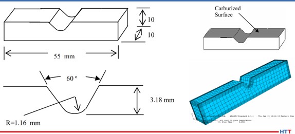
Figure 2. Coupon dimensions, selectively carburized surface, and finite element model
The steel alloy Pyrowear® 53 was chosen as the candidate material for this project. Table 1 shows the base chemistry of Pyrowear 53. The alloy is used extensively in the aerospace industry as a transmission gear material due to its ability to resist softening at high temperature in the hard carburized case, while maintaining high core impact strength and fracture toughness. A specially designed “V” notch 3-point bend fatigue sample was created by the company in conjunction with input from experts at the Army Gear Research Lab at NASA-Glenn and Bell Helicopter. The design was chosen to mimic behavior of a gear tooth root during loading. Figure 2 shows the dimensions of the coupon, the selectively carburized surface, and the finite element model used to explore the effects of process parameter changes on residual stress.
Figure 3. Schematic of intensive quenching orientation for Phase 1 study
A total of 40 coupons were manufactured and selectively carburized. The coupons were then split into two groups. Both groups were subjected to the same 1674°F (912°C) austenitizing, - 110°F (-79°C) cryogenic treatment, and double temper at 450°F (232°C). However, the two groups differ in the method of quenching, with one group quenched using the standard oil quenching practice for Pyrowear 53 and the second group quenched using the Intensive Quenching method. The two groups were processed separately. The Intensive Quenching unit utilized in this project uses a high velocity water stream to quench one component at a time. Figure 3 shows the coupon orientation within the intensive quenching unit. The blue arrow indicates the direction of water flow over the coupon.
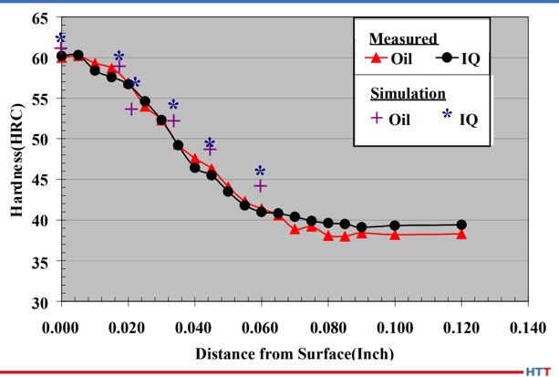
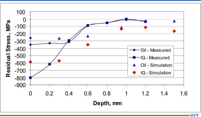
After processing all of the coupons and modeling the two processes using the same heat treatment simulation software, a comparison was made between the two processes and the simulation. Figure 4 shows the hardness profile comparison at the center of the notch. As seen, the hardness profiles are equivalent between the two processes. This is expected as the carbon and other alloy content in the material is identical between the two processes. The simulation also matches the experimental data well. While the hardness profiles are identical between the two processes, the residual stress profiles at the center of the notch are not the same, as shown in Figure 5. The intensively quenched coupon has a surface compressive stress of 800 MPa, more than double the compression induced by oil quenching. However, at 0.4 mm, the profiles converge. This is significant as the surface can now carry a higher load, yet no detrimental effects are seen subsurface. Again, the simulation matches the experimental results well.
Satisfied with the increased surface compressive stress gained through the use of Intensive Quenching, 3-point bend fatigue testing was initiated at Case Western Reserve University. Load control was applied, with a minimum to maximum load ratio of 0.1 used to maintain a state of cyclic tension. This type of loading ensures the sample remains stationary throughout the duration of the test.
Figure 4. Phase 1 hardness profile comparison between oil quench, Intensive Quench, and DANTE simulations of the two processes
Figure 5. Phase 1 residual stress profile at the notch center comparison between oil quench, intensive quench, and DANTE simulations of the two processes
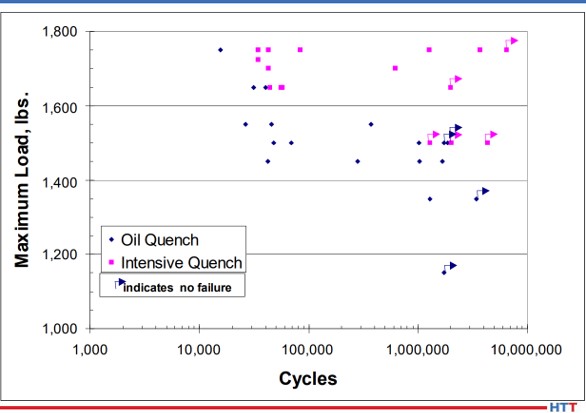
Figure 6 shows the results of the bend fatigue testing. It appears from Figure 6 that the increased residual surface compression of the intensively quenched coupons contributed to an increase in bend fatigue performance when compared to the oil quenched samples. However, some scatter does exist. Several parameters could have influenced these results.
First, during coupon manufacturing, the notch was created in the coupon using a milling operation and then heat treated. After heat treatment, no finishing operation was performed on the notch. Therefore, the possibility of surface defects existed. Any surface defect can create a stress riser, creating a stress condition which exceeds the expected stress given the loading conditions and geometry. However, surface defects would not be consistent coupon to coupon, and therefore have the potential to skew fatigue results.
Figure 6. Phase 1 bending fatigue comparison between oil quench and intensive quench
The second parameter that could have influenced the scatter in the fatigue results is related to the intensive quenching process itself. The process is dependent on a steep temperature gradient to generate the greatest level of compressive stress. This requires high velocity water to impact the component quickly, as any delay or low velocity water impingement can create shallow temperature gradients. Using the DANTE software, it was determined that in order to generate the greatest amount of surface compression, full flow must be achieved in a maximum of one second. This was a significant discovery that may have gone unnoticed if simulation was not used to explore process parameter sensitivities. It was unclear if the equipment operation met this maximum time restraint during processing of all coupons. However, due diligence was given to system operation in future experiments with improved consistency.
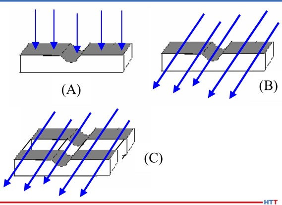
Figure 7. Schematic of intensive quenching orientations for Phase 1A study
Another processing parameter that has the potential to influence residual stress generated during an intensive quenching operation is the orientation of certain geometric features relative to the high velocity water flow. Again, the DANTE software was utilized, in lieu of expensive physical testing, to determine the optimum orientation of the fatigue sample in the intensive quenching unit. Figure 7 shows the three orientations evaluated. The orientation in Figure 7(A) has the water impinging on the notch surface and Figure 7(B) has the water impinging on the side of the coupon, with water flowing parallel to the notch. Recall that the original coupon orientation, shown in Figure 3, has the water impinging on the top of the coupon and flowing perpendicular to the notch. The final configuration, shown in Figure 7(C), places two coupons in the chamber side-by-side. This configuration has the potential to create an even steeper thermal gradient within the coupon due to the two coupons sharing thermal energy from being in contact with one another, and thus having a slower cooling rate in the core than a single coupon.
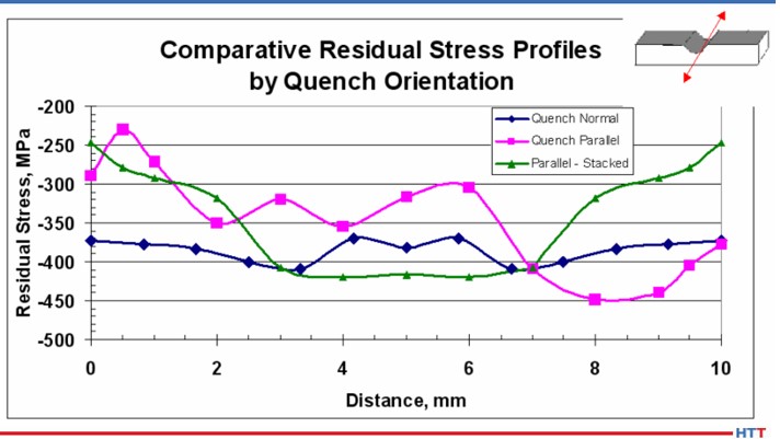
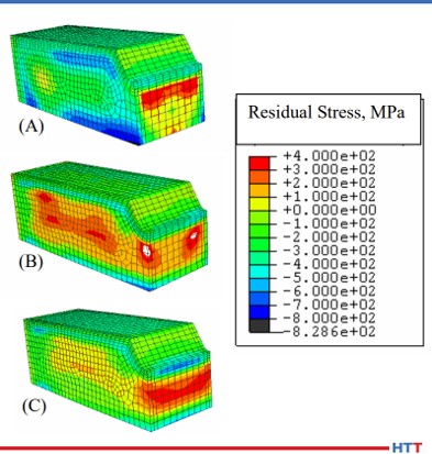
Figure 8 shows the surface residual stress across the width of the notch center, as shown by the red arrow in the Figure 8 inset, for the three orientations predicted by the simulation. Of the three orientations evaluated, orientation (A) resulted in the greatest magnitude of compression, as well as remaining the most consistent across the width of the notch. The residual stress contour plots of the three orientations, shown in Figure 9, confirm the uniformity of the residual stress profile across the width of the notch for orientation (A). The other two orientations show markedly reduced compressive surface stress near the edges of the notch. This type of profile would most likely fail in fatigue at those locations with reduced surface compression. To achieve the most consistent performance results, the most uniform surface condition should be sought.
Figure 8. DANTE residual stress profile predictions across the width of the notch center, as shown schematically in the figure inset, for the Phase 1A study
Figure 9. DANTE residual stress predictions for the Phase 1A study
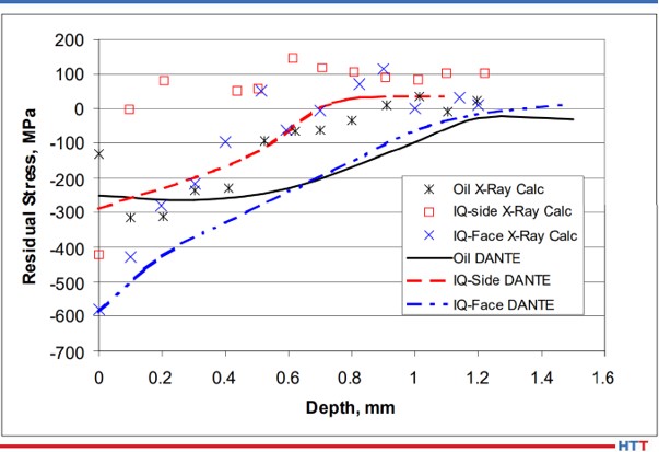
The residual stress profiles at the center of the notch are shown in Figure 10 for oil quenched coupons, intensively quenched coupons with orientations (A) (“IQ-face”) and orientation (B) (“IQ-side”), and the company simulation results for the three processes. As predicted by simulation, and confirmed by X-ray diffraction measurements, the intensively quenched coupon in orientation (A) results in the highest magnitude of residual surface compressive stress, as well as having the deepest compression. The measurements also revealed that intensively quenching the coupon geometry in orientation (B) results in a slight increase in surface compression, when compared to oil quenching, but the compression is reduced much quicker in the orientation (B) coupon. Based on the simulation results, it was surmised that orientation (A) would outperform orientation (B) in bend fatigue, and oil quench would outperform orientation (B). Due to the poor residual stress distribution predicted for orientation (C), no coupons were processed in this orientation.
Figure 10. Residual stress profile measurements and predictions at the notch center for orientations A and B of the Phase 1A study
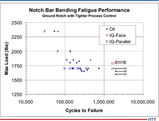
Figure 11 shows the bend fatigue results for the oil quenched coupons and the intensively quenched coupons in orientation (A) (“IQ-Face”) and orientation (B) (“IQ-Parallel”). As predicted from information gleaned from the DANTE simulation, orientation (A) outperformed the oil quenched coupons. The orientation (A) coupon recorded an endurance limit of approximately 1800 MPa, while the oil quenched coupons recorded an endurance limit of approximately 1600 MPa. This difference is approximately equal to the difference in near surface compressive stress induced by the two processes. The orientation (B) coupons failed to successfully complete a test at the loads chosen. Convinced that increasing the magnitude of surface compression through a process change could improve fatigue performance in transmission gears, Phase Two was initiated to evaluate the process change on an actual gear component.
Figure 11. Phase 1A bending fatigue comparison between oil quench and Intensive Quench
Conclusion
In conclusion, a project was launched to use heat treatment modeling, in conjunction with physical testing, to determine the effects of a process change designed to induce a greater magnitude of compressive surface stress to improve bend fatigue performance of a low-alloy gear steel. Pyrowear 53 was chosen as the gear steel and Intensive Quenching was chosen as the process change to induce a greater magnitude of residual surface compressive stress. Before any testing was initiated, DANTE modeling was used to show that intensive quenching could indeed produce a greater magnitude of surface compression, possibly improving bend fatigue performance by introducing a compressive mean stress and lowering the actual stress witnessed by the component. This modeling was also used to determine the maximum amount of time which may be used by the intensive quenching equipment to reach a full flow condition and still produce an increase in residual surface compression, as well as evaluate the residual stress profile of several different intensive quenching orientations.
Using this modeling to direct physical testing, hardness, residual stress, and bend fatigue performance were evaluated in coupons quenched in oil and coupons intensively quenched in three different orientations. The fourth orientation was not tested as modeling showed the residual stress profile to be unfavorable. Physical testing confirmed the modeling results: hardness profiles are equivalent between the processes, and residual stress profiles coincide with modeling results. Bend fatigue performance was indeed increased by increasing the magnitude of surface compressive stress. Phase One of the project showed that bend fatigue performance was improved by increasing the magnitude of the part’s surface compressive stress and demonstrated that modeling can be an invaluable tool when evaluating process parameter changes on material performance.
References
1. N. I. Kobasko and V. S. Morganyuk, “Numerical Study of Phase Changes, Current and Residual Stresses in Quenching Parts of Complex Configuration,” Proceedings of the 4th International Congress on Heat Treatment of Materials, Berlin, Germany, 1 (1985), 465-486.
2. N. I. Kobasko, “Intensive Steel Quenching Methods. Theory and Technology of Quenching”, SpringerVerlag, New York, N.Y., 1992, 367-389.
3. N. I. Kobasko, “Method of Overcoming Self Deformation and Cracking During Quenching of Metal Parts,” Metallovedenie and Termicheskay Obrabotka Metallov (in Russian), 4 (1975), 12-16.
4. M. Hernandez et al., Residual Stress Measurements in Forced Convective Quenched Steel Bars by Means of Neutron Diffraction”, Proceedings of the 2nd International Conference on Quenching and the Control of Distortion, ASM, (1996), 203-214.
5. M. A. Aronov, N. I. Kobasko, J. A. Powell, J. F. Wallace, and D. Schwam, “Practical Application of the Intensive Quenching Technology for Steel Parts,” Industrial Heating Magazine, April 1999, 59-63.
6. A. M. Freborg, B. L. Ferguson, M. A. Aronov, N. I. Kobasko, and J. A. Powell, Intensive Quenching Theory and Application for Imparting High Residual Surface Compressive Stresses in Pressure Vessel Components,” Journal of Pressure Vessel Technology, 125 (2003), 188-194.
7. B. L. Ferguson, A. M. Freborg, and G. J. Petrus, “Comparison of Quenching Processes for Hardening a Coil Spring,” Advances in Surface Engineering, Metallurgy, Finishing and Wear, SAE (01) 1373, (2002).
About the Author: Justin Sims has been with DANTE Solutions for eight years and is an excellent analyst and expert modeler of steel heat treat processes using the DANTE software. His project work includes development, execution, and analysis of carburization, nitriding, and quench hardening simulations. He has developed the DANTE HELP packages and is the primary trainer and software support person for the DANTE software.
AMS2750F? What are the new changes? How do you implement them? This informative article from Heat TreatToday's Aerospace 2021 issue will help you navigate through the uncertainty of these changes to ensure successful compliance.
This Technical Tuesday is an original content contribution from Jason Schulze, the director of technical services at Conrad Kacsik Instrument Systems, Inc. Check out other technical articles here.
Jason Schulze Director of Technical Services Conrad Kacsik Instrument Systems, Inc.
Introduction
AMS2750F has been released for approximately 7 months now. This specification applies to manufacturers and suppliers who heat treat aerospace material. AMS2750F is typically communicated via industry standards such as SAE/AMS specifications as well as customer purchase orders and part prints. This specification gets even more complex when you apply Nadcap heat treat accreditation to the equation as Nadcap has a checklist dedicated to AMS2750, which, as of January 2021, has yet to be released.
In this article we will examine some of the changes within AMS2750F as well as discuss the implementation process for suppliers.
AMS2750F Changes
General Changes
AMS2750F now has 25 tables, where there were previously 11. These tables are no longer at the end of the specification (like most SAE/AMS specifications); they are now placed throughout the specification adjacent to paragraphs to which the rewrite team thought they applied. The challenge with this is that all aspects of AMS2750 are interconnected. For example, one change in the qualified operating range of a furnace will directly affect other areas, such as instrument calibration and the temperature at which an SAT is performed.
Previously, temperature values were expressed in whole numbers. They are now expressed to the tenth of a degree (X.X°F). With this change, I would recommend suppliers follow suit in their own pyrometry procedures and associated documents: think of it as comparing apples to apples.
Scope and Definitions
The definitions section is important, especially to those who are new to AMS2750F who may be working to interpret some of the verbiage within the specification. The specification has increased the number of definitions from 79 to 87. A good example of these definition changes is the comparison of expendable thermocouples versus nonexpendable thermocouples.
EXPENDABLE SENSOR: Sensors where any portion of the thermal elements are exposed to the thermal process equipment environment.
NONEXPENDABLE SENSOR: Sensors having no portion of the thermal elements exposed to the thermal process equipment environment.
This example is especially important because it is such a major change from the previous revision of AMS2750. The definitions section within AMS2750F should be utilized often by suppliers to ensure comprehension and conformance.
Thermocouples
As simple as thermocouple technology is, there are many requirements within AMS2750F governing thermocouple usage, error, replacement, etc. Previously, AMS2750 did not address resistance temperature devices (RTDs). It now requires RTDs be nonexpendable, noble metal, and ASTM E1137 or IEC60751 (Grade A).
I do not see this next change as anything major, because what I’m witnessing in my consulting all around the US and Mexico are that suppliers already conform. Thermocouple hot junctions (the tips of the thermocouple measuring temperature) are made by either twisting, welding, or a combination of both.
In my experience, it is rare to see a thermocouple supplier/manufacturer issue a thermocouple certification that is nonconforming. Whenever there are issues with thermocouples, it is typically because the supplier did not communicate the correct information. With that, thermocouple error should be considered and communicated correctly.
Thermocouple permitted error has changed to the following:
Type R & S: ±1.0°F or ±0.1%
Type B: ±1.0°F or ±0.25%
Base metal: ±2.0°F or ±0.4%
AMS2750E permitted ±4.0°F or 0.75% for TUS, load and furnace thermocouples.
Exceptions:
Note 11: For temperatures <32°F or <0°C for Types E and T only, calibration accuracy shall meet the following:
Type E: -328 to 32°F, ±3.0°F or ±1.0 % for either, whichever is greater
Type T: -328 to 32°F, ±1.8°F or ±1.5 % for either, whichever is greater
Note 13: When correction factors are used, type B load sensors shall meet calibration accuracy of ±2.7°F or ±0.5% and types R and S load sensors shall meet calibration accuracy of ±2.7°F or ±0.25%
AMS2750 has always required that the results of an SAT and TUS must reflect corrected temperatures. This would mean when expressing the final ± readings of a TUS, those readings must be identified as corrected values. The challenge may come when you need a correction factor from a thermocouple certification where there is not a temperature value for the test. AMS2750F now addresses this situation:
PARA 3.1.4.8 - Interpolation of correction factors between two known calibration points is permitted using the linear method.
PARA 3.1.4.9 - Alternatively, the correction factor of the nearest calibration point shall be used.
PARA 3.1.4.10 - Whichever method is used shall be defined and applied consistently.
Each supplier must decide what method they will utilize and document this. Know your customer requirements; some customers may not permit certain methods.
Sensor usage has changed dramatically, especially for expendable test sensors. These thermocouples are now limited to a single use above 1200°F regardless of the type. Between 500°F and 1200°F, Type K may be used five times or three months, whichever occurs first and for Type N, 10 times or three months, whichever comes first. Below 500°F, Type K may be used for three months with no limit to the number of uses, and Type N may be used for six months, with no limit to the number of uses. I can understand how this may seem like a lot to understand and filter through, but I can assure you, we will get used to it as we did with AMS2750E.
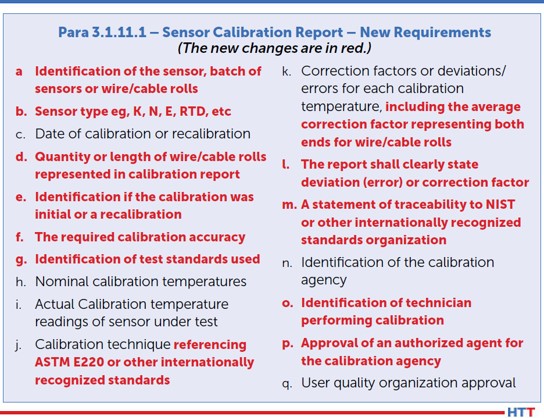
Thermocouple certification requirements have also changed. I do not foresee any issue with this as what is listed is, for the most part, already on existing thermocouple certifications. I would advise suppliers to check the requirement in bullet point “E.” (Figure 1)
Figure 1
Instrumentation
There were several major changes within the instrumentation section. The first one is readability of furnace recording and field test instruments. Previously, readability for all furnace and field test instruments was 1.0°F; it is now 0.1°F, or to the tenth of a degree. Suppliers may find this challenging to meet as not all field test instruments on the market are capable of this. An easy way to test yours is to either source or read the value on your field test instrument at 999°F. Then, increase the temperature to 1000°F.
On some units, when a temperature is reading/sourced below 1000°F, it will show to the tenth of a degree, but when increased above a tenth of a degree, the value in the tenths place will be removed and only whole numbers will be shown. If this is the case, you will need to purchase a new field test instrument which displays values to the tenth of a degree regardless of whether values go above 1000°F.
The second major change is timers or digital clocks on recording devices. This change makes sense, as most thermal cycles used to achieve metallurgical transformation are time-dependent and have specific tolerances that apply. AMS2750F now requires that these timing devices must be accurate to within ±1 minute per hour. There is a caveat which states that as an alternative, suppliers may have a synchronized system linked to NIST via internet system which is verified monthly and will support the ±1 minute per hour requirement. With that, a new paragraph, regarding stopwatch calibration and accuracy requirements, has been inserted adjacent to the recording device timing calibration requirements.
The third change, simple and straight forward, is that the instrument number or furnace number must be stated on the calibration sticker.
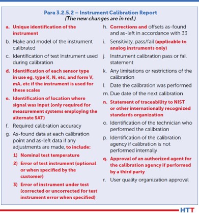
Additionally, changes have been made to what is required on an instrument calibration report. (Figure 2)
Figure 2
System Accuracy Testing (SAT)
There are several changes within the SAT section that should get attention. One which may continue to be overlooked is whenever an SAT cannot be performed (not that one fails), but if no product was run and the furnace was locked out, the SAT could be performed with the first production run (AMS2750E, para 3.4.2.4). This is no longer an option. AMS2750F now states that, in this situation, the SAT must be performed prior to putting the furnace back into service (or prior to production).
Furnaces that have multiple qualified operating ranges (i.e., CL2 from 1000°F to 1600°F and CL5 from 1601°F to 2000°F) must have the SAT performed in each range, at least annually. This means that if you typically run production at 1550°F and SATs are run at the same time, at least annually, an SAT must be processed above 1600°F to catch the CL5 range.
The alternate SAT process was the source of much confusion when revision E was released. Previously, single use thermocouples (i.e., load thermocouples) did not require an SAT per AMS2750D, para 3.4.1.2. When AMS2750E introduced the alternate SAT, the wording was so poor it caused suppliers to misunderstand the requirement, and subsequent audits yielded quite a few related findings. I have written previous articles explaining the alternate SAT process in detail, so I will not be going into this topic too deeply. For information, please visit www.heattreattoday.com and search Jason Schulze.
The changes within the alternate SAT section primarily amount to clarification and incorporation of what was previously in Nadcap’s pyrometry reference guide. That being said, there really isn’t much to speak of in this section for existing Nadcap suppliers, but one item to point out is how the wording has changed. Previously, it applied to single use sensors or sensors which were replaced more frequently than the SAT frequency requirement. This has been changed to state that the alternate SAT applies to load sensors used only once. Nadcap heat treat auditor advisory HT-20-010 has clarified this further. If load sensors are used more than once, the alternate SAT does not apply, and the comparison SAT must be used.
There were some minor changes to what is required on the comparison SAT report. (Figure 3)
Figure 3
Documentation related to the alternate SAT as well as the SAT waiver have been introduced. These should be examined closely by those suppliers to whom it may apply.
Temperature Uniformity Surveys (TUS)
Among many of the changes in this section, there is one that is not stated outright but is based on verbiage changes within Tables 18 and 19 of revision F regarding frequency. In AMS2750E, Tables 8 and 9, the statement reads “Initial TUS Interval” and “Extended Periodic TUS Interval.” Due to the wording, it was assumed that if four passing consecutive TUSs were needed before going to a reduced frequency, the initial TUS would count as part of the four needed. The modified wording in Tables 18 and 19 of AMS2750F now reads “Normal Periodic Test Interval” and “Extended Periodic Test Interval.” With this change in verbiage, the initial TUS does not count toward the needed consecutive tests to reduce TUS frequencies.
If a supplier uses vacuum furnaces for thermal processes and both partial pressure and low vacuum is used, a TUS must be performed annually in the partial pressure range using the gas applied during production. This is a rather simple change, although it is important to recognize that partial pressure gases, depending on certain variables, can affect the uniformity in the area in which the gas enters the furnace.
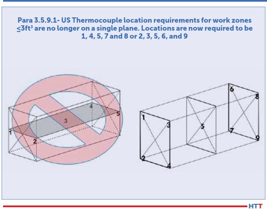
Thermocouple location for work zone volumes less than three cubic feet has changed. AMS2750E/Nadcap previously required that the five TUS thermocouples be placed on a single plane. AMS2750F has revised this to require each test thermocouple be placed diagonally opposite of each other. Using Figure 4, this could mean suppliers may choose locations 1, 4, 5, 7, and 8 or 2, 3, 5, 6, and 9.
Suppliers familiar with GE’s P10TF3 specification will recognize this next change as it was a GE requirement long before SAE/AMS introduced it into AMS2750F. Previously, data collection during TUSs needed to start prior to the first furnace or test thermocouple reaches the lower end of the tolerance (AMS2750E, para 3.5.13.3.1). This has changed and now requires data collection to begin when the furnace and TUS thermocouples are no fewer than 100°F below the survey temperature.
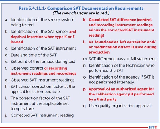
The documentation or TUS certification requirements have also changed. Considering that there are so many changes within this section, I will merely point out the letter annotations that apply to changes within Para 3.5.16.1: B, D, F, G, H, J, L, O, R, S, and Y. Some of these items contain simple verbiage changes, although most of them are solid changes and should be incorporated into suppliers’ procedures and forms.
Figure 4
Rounding Requirements
Previously, AMS2750E permitted rounding in accordance with ASTM E29. To the delight of many users, I am sure, this has changed. AMS2750F now permits rounding in accordance with the following options:
All rounding must be applied in accordance with a documented procedure and used in a consistent manner.
Rounding to the number of significant digits imposed by the requirement is permitted in accordance with ASTM E29 using the absolute method or other equivalent international standards. (Previously, the only method permitted was the rounding method.)
The rounding method built into commercial spreadsheet programs is also acceptable.
All specified limits in this specification are absolute and out of tolerance test data cannot be rounded into tolerance.
Rounding must only be applied to the final calibration or test result.
Quality Provisions
The only change in this section is in regard to pyrometry service providers. The requirement now states, “Beginning 2 years after the release of this specification, third-party pyrometry service provider companies shall have a quality system accredited to ISO/IEC 17025 from an ILAC (International Laboratory Accreditation Cooperation) recognized regional cooperation body. The scope of accreditation shall include the laboratory standards and/or field service as applicable.” It is important to keep in mind that, when verifying conformance to this, the supplier’s scope of accreditation should include reference to AMS2750 with regards to instrument calibration, SAT, or TUS or all three if that is what is performed at your facility by an outside service provider.
Implementation of AMS2750F
he implementation of AMS2750F with suppliers’ systems should be two-fold: not only what is implemented but when it is implemented. Right now, AC7102/8 Rev A, as it applies to AMS2750F, is in the review stage. Its projected release date is April 2021. Regardless, once the new revision of AC7102/8 is released, suppliers will have 90 days to implement AMS2750F.
Implementing AMS2750F must be done in its entirety, not partially. This means internal procedures, forms, purchase orders, etc. should be revised in the background in conjunction with training. Once your team is familiar with the new changes, then all the revised documents should be released at one time. This ensures the whole of AMS2750F is implemented at once and not in stages.
Nadcap heat treat auditor advisory HT-20-007 requires that all thermocouples issued on or after Jan. 1, 2021 must be certified in accordance with AMS2750F. By this time, suppliers should have already revised purchase orders to require this and may have thermocouple certifications reflecting AMS2750F.
About the Author: Jason Schulze is the director of technical services at Conrad Kacsik Instrument Systems, Inc. As a metallurgical engineer with over 20 years in aerospace, he assists potential and existing Nadcap suppliers in conformance as well as metallurgical consulting. He is contracted by eQualearn to teach multiple PRI courses, including pyrometry, RCCA, and Checklists Review for heat treat.


 When the new additive research facility at the Oregon Manufacturing Innovation Center Research & Development (OMIC R&D) opens in Scappoose, Oregon, the facility will acquire a hot isostatic press. Operating at a temperature of 2550°F (1400°C) and a pressure of up to 30,000 psi (2070 bar), the new press will give OMIC researchers the ability to study densification of metals as well as how HPHT can modify the grain structure to enhance the mechanical properties of additively manufactured parts.
 “For OMIC R&D to fulfill our mission, we must have world-class cutting-edge capabilities to support our applied research & development projects. We accomplish this by partnering with some of the best companies in the world in their respective fields and identifying and utilizing their unique technologies and expertise. Our solutions can be implemented by regional, national, and international partners to increase their competitiveness,” says Craig Campbell, executive director at OMIC. “We chose Quintus as a partner because the company is continually innovating, and developing new processes such as High Pressure Heat Treatment, or HPHT.”