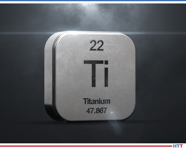
Titanium: A Fascinating History & Future
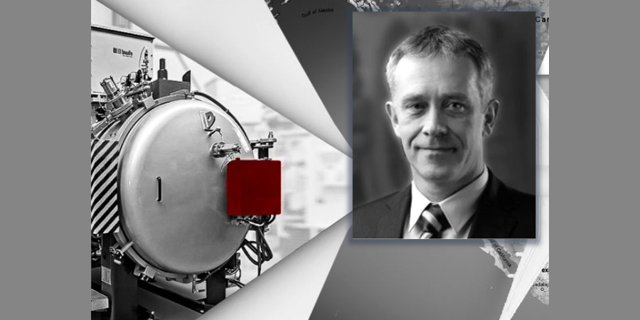
![]() Journey through this article by Robert Hill, FASM, president of Solar Atmospheres of Western PA, to explore the history, problems, solutions, and impacts this metal has had on multiple varied industries.
Journey through this article by Robert Hill, FASM, president of Solar Atmospheres of Western PA, to explore the history, problems, solutions, and impacts this metal has had on multiple varied industries.
This original content piece was first released in Heat Treat Today’s Aerospace 2021 Issue. Click here to access the digital edition and all previous print/digital editions.

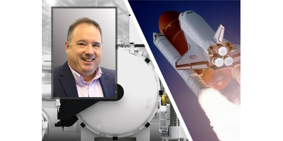
President
Solar Atmospheres of Western PA
In 1987, Michael Suisman, president of Suisman & Blumenthal, sounded a stern warning that a “titanium disease” was spreading throughout the land. His clinical description was as follows:
Symptoms: The patient is completely overcome by the metal titanium. He or she tends to eat and sleep titanium, pushing all other metals out of his or her system. The patient will talk for hours about the virtues of titanium, extolling its remarkable qualities. Any blemish on titanium’s image, any negative characteristic will tend to be dismissed. Titanium’s feast-or-famine existence seems to only intrigue the patient.
Earliest known causes: In the 1950s, a number of patients were overcome with titanium, describing it as the “wonder metal.” The side effects of the “wonder metal” syndrome took many years to disappear.
Similar disease: See infatuation.
Length of disease: Lifetime.
Cure: None known.
After working with titanium for more than two decades, I have fallen victim to the “titanium disease.” What makes this metal so unique? With a quick look at the history and distinctive properties, one can easily recognize the attraction.
History
Titanium was discovered by an English pastor named William Gregor in the 1700s. In the 1800s, small quantities of the metal were produced. Before World War II, titanium as a useful metal was only a tantalizing laboratory curiosity. At that time, titanium was only valuable as an additive to white paint in its oxide form. It took the long and expensive arms race between the United States and the Soviet Union in the 1940s to create the need to solve many of titanium’s complex problems.
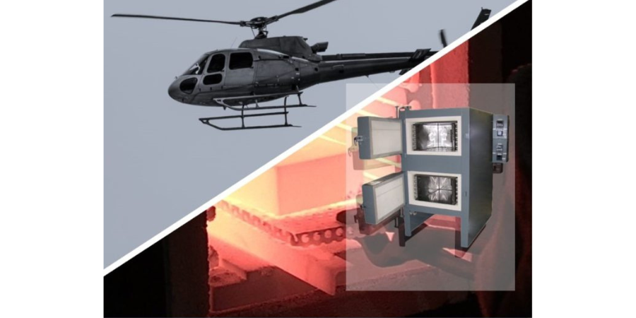
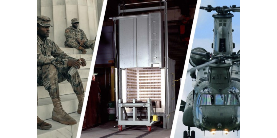
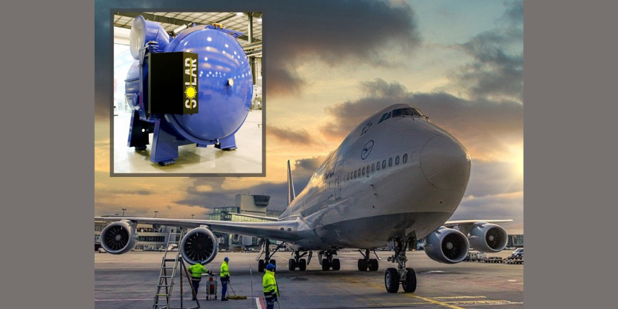
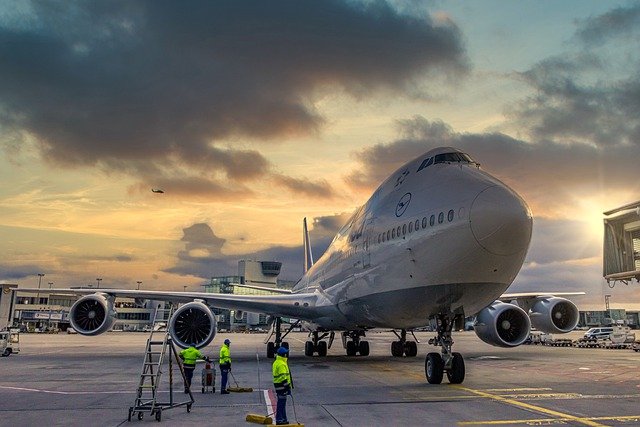
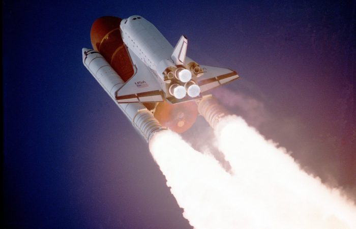
 Since the end of the Cold War, titanium has matured primarily as an aerospace material. However, this “wonder metal” has expanded to commercial markets such as artificial body implants, golf clubs, tennis rackets, bicycles, jewelry, heat exchangers, and battery technologies.
Titanium’s unusual metal attributes include a strength comparable to steel – but 45% lighter. It is twice as strong as aluminum–but only 60% heavier. It is both biologically and environmentally inert. It will not corrode. The metal is nonmagnetic and can hold strength at high temperatures because it has a relatively high melting point. Finally, titanium has a very low modulus of elasticity and excellent thermal conductivity properties. For thermal processors, these “spring like” properties allow titanium to be readily formed or flattened with heat and pressure.
Problems
For all of its outstanding attributes, titanium is still the problem child of the metallurgical family. It is exceedingly difficult to obtain from its ore, which commonly occurs as black sand. If you scoop up a handful of ordinary beach sand and look closely, you will likely see that some of the grains are black–this is titanium ore. In certain places in the world, especially Africa and Australia, there are vast black sand deposits. Although titanium is the ninth most abundant element on the earth, turning that handful of sand into a critical jet engine blade or body implant is a significant undertaking. The refining process is about 10,000 times less efficient than making iron, which explains why titanium is costly.

Source: Solar
Titanium never occurs alone in nature, and it is a highly reactive metal. Known as a transition metal, it can form bonds using electrons from more than one of its shells or energy levels. Therefore, titanium is known as the streetwalker metal. Metallurgists are aware that titanium is renowned to pick up other elements quite readily during many downstream thermal and chemical processes. These reactions are often harmful to the advantageous properties of titanium and should be avoided at all times.
Solution
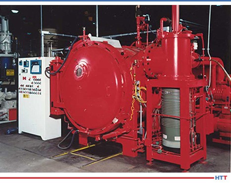
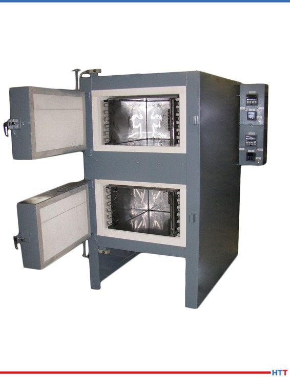
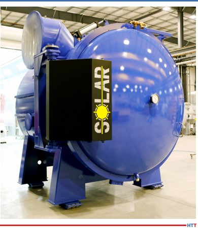
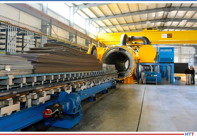
Since titanium has a tremendous affinity to pick up other elements at elevated temperatures, primarily oxygen and hydrogen, the only way to heat treat titanium successfully is to utilize high vacuum atmospheres. High vacuum levels of x10-5 Torr minimum and low leak rates of five microns per hour maximum are the parameters needed to retain this metal’s desired properties. An oxygen-rich atmosphere results in a hard “alpha case” surface condition. A hydrogen atmosphere results in a hydride condition, which makes titanium very brittle to the core. Both conditions can be extremely detrimental to any critical titanium component.
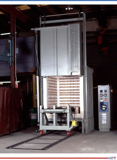
With high pumping capability and tight pyrometric controls, vacuum furnaces successfully provide various treatments on the “wonder metal” while avoiding the “streetwalker” syndrome. The treatments include inert stress relieving, solution treating, aging, and degassing treatments. After proper processing, bright and clean parts with low hydrogen content and zero alpha case are the norm.
The recycling of titanium is of a different magnitude than other metals due to its value. It took a shortage of titanium in the 1980s–and some innovative metallurgy–to transform valuable titanium scrap back into a qualified ingot. To do this, metallurgists used the reactivity of the metal to their advantage. Because titanium is very ductile and extremely hard to grind into powder, metallurgists learned how to use hydrogen to their advantage. Adding hydrogen to turnings and scrap makes the titanium brittle and enables the material to be pulverized into fine powders. The final product must then be thoroughly degassed or dehydrided to enter back into the revert stream, because every pound of titanium is precious.
Source: Solar
The reactivity of titanium also assists the metallurgist to apply various surface treatments. Nitride and carbide surfaces, when used, add further protection to titanium while making the exterior harder.
Alloys
Titanium alloys are divided into four distinct types: commercially pure, alpha, beta, and alpha beta. Commercially pure grades have no alloy addition, and therefore they have very little strength. This grade of titanium is used when corrosion resistance is of greater importance. Alpha alloys are created with alpha stabilizers such as aluminum. They are easy to weld and provide a reliable strength at elevated temperatures. Beta alloys use stabilizers such as molybdenum or silicon which makes these alloys heat treatable to higher tensile strengths. Finally, the most used titanium alloy are the alpha-beta alloys. These heat treatable alloys are made with both alpha and beta stabilizers creating an excellent balance between strength, weight, and corrosion resistance.
Summary
Despite all the advances, titanium and its many alloys have not reached their apex in popularity in the world. Is there any other element that calls to mind the notion of strength quite like titanium? For what reason has this metal, named after the Titans of Greek mythology, not yet reached its full potential? If it were not for the expense, we would undoubtedly have titanium cars, houses, jets, bridges, and ships. Unfortunately, the cost of titanium keeps the “titanium disease” at bay.
About the Author: Robert Hill, FASM, president of Solar Atmospheres of Western PA, began his career with Solar Atmospheres in 1995 at the headquarters plant located in Souderton, Pennsylvania. In 2000, Mr. Hill was assigned the responsibility of starting Solar Atmospheres’ second plant, Solar Atmospheres of Western PA, in Hermitage, Pennsylvania, where he has specialized in the development of large furnace technology and titanium processing capabilities. Additionally, he was awarded the prestigious Titanium Achievement Award in 2009 by the International Titanium Association.
Titanium: A Fascinating History & Future Read More »