Heat Treat Today publishes eight print magazines a year and included in each is a letter from the publisher, Doug Glenn. This letter first appeared in Heat Treat Today's November 2022 Vacuum Heat Treat Systems print edition.
Doug Glenn Publisher and Founder Heat TreatToday
Immediate credit for the content of this column goes to Mark Mills, author of The Cloud Revolution: How the Convergence of New Technologies Will Unleash the Next Economic Boom and a Roaring 2020s, and podcast host of The Last Optimist, the source for most of the below content — see episode #20, “Congress & the ‘Groundbreaking’ Energy Spending Act: Top 10 Truths to Keep in Mind.”
Contact us with your Reader Feedback!
Heat TreatToday interviewed Mr. Mills not long ago. If you’d like to listen to, watch, or read that interview, go to our website and search for “Mark Mills” or Bing/Google search for “Heat TreatRadio #73 Mark Mills.”
Here are some interesting thoughts from The Last Optimist podcast, episode #20.
Energy transformations are slow. In the last 20 years, the Western world has spent over $5 trillion to avoid using hydrocarbons, but reduced the percentage share by only 2%, from 86% to 84%. Remarkably, the burning of wood, today, provides 500% more energy to the world than all the world’s solar panels combined. Burning wood will most likely not change in the near future; in fact, more wood is burned today than 20 years ago.
Economic growth always produces more demand for energy. Wealthy economies use 500–5,000% more energy per capita than poor economies. Ironically, wealthy economies use energy more efficiently than poor economies but consume vastly more. Implication: the wealthier we become the MORE energy we will consume.
The shale revolution (mostly happening in America) is the world’s biggest energy revolution. From 2005-2020, the amount of energy provided from shale was TWICE the amount of energy produced from wind and solar arrays combined. This is the largest increase in energy supply in the history of the world, anytime, anywhere. The next closest “revolution” was the Saudi oil fields, but the shale fields have produced nearly DOUBLE the amount of energy.
Green energy is NOT carbon free. According to a study done by Volkswagen, the first 60,000 to 70,000 miles of driving a diesel-powered Volkswagen emits less CO2 than driving an electric vehicle. Its only AFTER that many miles that the vehicle is a net saver of CO2.
Energy tech cannot emulate the digital tech performance curve. The exceptionally high reductions in cost of computers and other digital technologies have been unprecedented in world history. Unfortunately, those who claim that green energy developments will see the same drastic reduction in costs are misled and ignore, at their own peril, the physics of energy conversion and transmission. That’s not to say there won’t be significant improvements in energy technology – in fact, there have already been and will continue to be vast improvements, but not to the scale of information/digital technology.
The energy transition hardware radically increases the demand for physical minerals and thus mining. The need for green energy minerals, the materials needed to build green energy materials like solar panels, electric vehicles, and wind farms, is 1,000% higher than building similar hydrocarbon-based hardware. In other words, the push for green energy will require a drastic increase in the need for minerals, requiring mining, which is currently a carbon intensive .
Energy transition policies — as currently presented — will cause prices to rise. This point ties in directly to point #6. If you increase the demand for materials, such as copper, cobalt, nickel, silicon, aluminum, and lithium, the price of these materials will increase precipitously and will therefore impact the price of all goods that use those materials. The energy sector is a minor user of these materials now, but if demand increase hundredfold, the energy sector will become a major user and will invariably push prices northward.
Scan QR code to listen to The Last Optimist podcast.
Green energy isn’t cheap. Every country who has thus far embraced, even in part, some sort of green energy has experienced a 200%–500% increase in consumer energy costs.
China is the OPEC of green energy minerals. It’s not so much that the mining of these minerals and rare-earth materials is done in China (some is but not all), but a huge majority of these minerals are refined in China. They are truly dominant. China’s share of mineral refining is more than double OPEC’s share of the world’s petroleum market.
Markets and consumer want reliable AND cheap energy. The most radical transition in society over the past century has been the percentage of time that mankind has had to invest in acquiring food and fuel. For most of human history, roughly 60-80% of all human exertion was spent acquiring food and fuel for existence. Today, thanks primarily to the discovery and utilization of hydrocarbons, that number is more in the range of 15%. One measure of an economy’s prosperity is the amount of time designated to getting food and fuel. The lower that percentage, the more prosperous a society. It has never been lower than today.
The 30-minute podcast from which this information comes is well worth a listen.
Find heat treating products and services when you search on Heat Treat Buyers Guide.com
Readers are checking out recent AMS2750 Rev. G changes and want some more information from Heat Treat Today about a specific clarification. Read the correspondence about the implications of AMS2750 Rev. G paragraph 3.1.1.5 about how to measure junction construction.
Douglas Shuler, lead auditor at Pyro Consulting, has written numerous articles with Heat Treat Today about AMS2750 standards. Check them out by searching "Doug Shuler" at www.heattreattoday.com.
READER QUESTION: After combing the new AMS2750 Rev. G, I found that paragraph 3.1.1.5 no longer allows thermocouples to be tack welded directly to parts, OR to representative dummy parts. This has been standard practice for decades. So I dug into it further with the folks from PRI and it turns out to be true. They’re now expecting load thermocouples to be either placed inside of a part (ends twisted and inserted), or inside the hole of a dummy block.
I’d done some searching online and there isn’t a single source talking about this major change. This could lead to a lot of failed upcoming Nadcap audits.
Doug Shuler Lead Auditor Pyro Consulting
Douglas (Doug) Shuler (Pyro Consulting) for Heat Treat Today: Historically (i.e. prior to Rev. F), AMS2750 was silent on measuring junction construction. In Rev. F, the construction of the measuring junction was as follows:
Measuring junctions shall be made by any combination of twisting and/or welding the thermal elements provided there is no addition of filler metal.
This raised concerns about both the use of quick tips and spot welding to make the measuring junction. The AMEC AMS2750 revision team engaged with Cleveland Electric Laboratories to perform testing on these measuring junctions as compared to the twisting/welding combinations.
The conclusion of the tests were that both quick tips and spot welding to a part/heat sink became unstable at temperatures above 2000°F. The quick tip crimping point and the spot welds showed rapid oxidation and increased errors in a short period of time. Based on the results of these tests the AMEC AMS2750 revision team put forth the following update in Rev. G:
Measuring junctions shall be made by either of the following methods:
Any combination of twisting and/or welding the thermoelements provided there is no addition of filler metal (including ungrounded and grounded MIMS).
Spot welding the thermoelements directly to a part, simulated part, or heat sink is permitted for temperatures ≤2000°F or 1100°C.
This allows spot welding measuring junctions for process temperatures at or lower than 2000°F. The team and AMEC members decided that quick tips were to unstable to permit their use going forward.
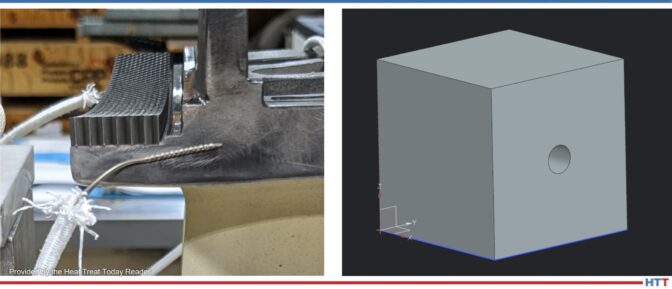
READER FOLLOW-UP: Our current method that we’re using is to twist the thermocouple using a set of Twister Pliers, then tack-weld that twist onto the part (first photo below). We’ve been doing this for parts up through brazing temperatures (~2150°F) without issue. We recently ran a furnace run around 2100°F with parts tack-welded as I’ve described AND had T/Cs that were just twisted with no tack weld. We noticed there was no significant difference in the temperature the TCs were reading. This was also our technique that we used at my previous company.
The way I read AMS2750 Rev. G was: You may twist and weld thermocouples to a part, but only for temperatures less than or equal to 2000°F.
To comply with Rev. G, we have gone ahead and made heatsink blocks to make sure we’re in compliance. Our new method of temperature measurement is twisting the wires and sticking the twisted end down inside of a block of solid metal (like the one I’ve shown below).
Source: Heat TreatToday Reader
We welcome your inquiries to and feedback on Heat Treat Today articles. Submit your questions/comments to editor@heattreattoday.com.
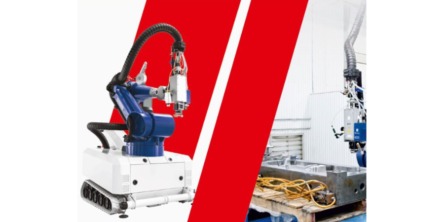
A commercial heat treater in Grand Rapids, MI is expanding its capabilities with robotic laser heat treating systems. This announcement was given with an open house invitation for the manufacturing community to witness this technology in action.
Laser Hard, Inc.'s technology is gaining momentum in automotive, mining, power generation, medical, aerospace and firearms industries, among others. Due to its low heat input and accuracy, companies request this process in place of other conventional methods that introduce a greater risk of cracking and distortion. The robot has built-in pyrometry for consistent heat at the work piece, reducing the risk of melting edges or overheating in an area that may have a thin cross section.
The open house will be on Thursday, October 13th, at 2766 3 Mile Road, Grand Rapids, MI 49534. There will be laser hardening demonstrations every hour from 2pm-6pm. Food and beverages from Pork Fat Slim's food truck will be available.
Find heat treating products and services when you search on Heat Treat Buyers Guide.com
Welcome to Heat TreatToday's This Week in Heat TreatSocial Media. You know and we know that there is too much content available on the web, so it’s next to impossible to sift through all of the articles and posts that flood our inboxes and notifications on a daily basis. Today, Heat TreatToday brings you another hot take of the latest compelling, inspiring, and entertaining heat treat chatter from the world of social media. We're looking at FNA chatter, some sweet technical (and not so technical) heat treat content, and a video of some hot steps.
Typically, we have some sick video of a racecar jumping off a building to shock you into your Friday. This time, since many of us are getting off the hype of being at FNA, listen to this breakdown on the differences between gas nitriding and plasma nitriding.
2. All That Chatter
Check out some of the chatter that everyone has been posting on heat treat topics over the last few months.
Did someone say "Jominy"?
Simmering Springs
Feeling hot?
?at the shimmer on these compression springs - fresh from heat treatment ovens 'cooking' @ 450 degree c
If you think that's ?, our divisions hot coiling line reaches 900 degrees!
— Lesjöfors Heavy Springs UK (@Lesjofors_UK) July 11, 2022
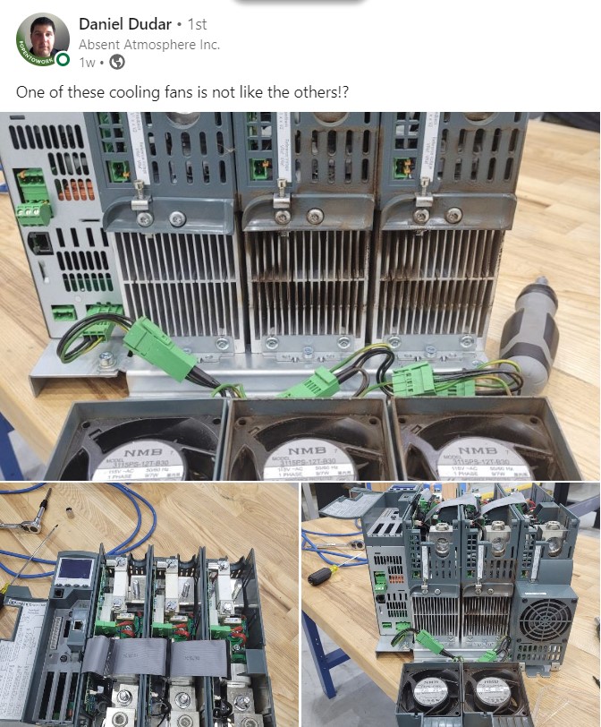
"One of these cooling fans is not like the other?!"
Screen Capture from Daniel Dudar via LinkedIn
3. Bumping Shoulders with Heat Treaters
It's great to connect with other folks in the industry. This past week has been an amazing opportunity to forge new relationships and strengthen old ones at MTI events, the Furnaces North America trade show, and student-professional meet-ups.
MTI Moments
FNA Interactions
FNA Conversations
Peter Sherwin gives the best technical session highlights on his LinkedIn page.
Time to take your afternoon coffee and read a few technical articles from around the industry. Got too many things to do? Put on an episode of Heat TreatRadio to enjoy as you commute home; they're so interesting, you may even get your family to start watching these videos instead of TV this weekend!
Stay Safe Out There
Where are you at in your cybersecurity know-how? Mike Harrison from Gasbarre is one of the sharp heat treaters out there who get's it. If you need an introduction into the world of cybersecurity, check out this article written on cybersecurity by Joe Coleman, cybersecurity officer at Bluestreak Consulting™.
Mesh Belts: A Report
Heat TreatRadio #82: Gun Part Treatments, Turning Up the Heat with Steve Kowalski. Click to –> Watch | Listen | Learn
5. Hot Feet
Have you ever had a moment like this at the end of a long week? Check out these fancy footsteps as you dance from the shop or plant floor into your weekend!
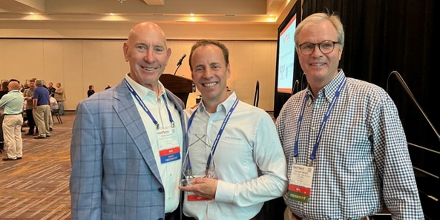
Jim Oakes, president of Super Systems, has been awarded the first ever Furnaces North America (FNA) Industry Award at the trade show's opening night kickoff reception.
This award is given to an individual in recognition of their contribution(s) and current/ongoing commitment to the betterment of the heat treating industry with one or more significant accomplishments in the last five years in the area of innovation, leadership, academia, or research.
The Metal Treating Institute’s 2018 President, Pete Hushek, who gave the award to Jim stated, "[No] one has been more deserving of this award than Jim Oakes. Having served as the President of ASM for two years and immediately being elected as president, serving two years during the pandemic, along with his service in a host of other technical standards groups, Jim’s leadership shined as he led two of the major associations the last five years."
Jim Oakes (pictured above in the center) stated upon receiving the award, "This is truly an incredible honor to be recognized by my peers. We don’t do what we do for awards. We do it to make a difference. It is through that difference that we make a better future for everyone. It has always been a pleasure to serve this great industry."
The FNA trade show is produced by the Metal Treating Institute in partnership with its media partner, Heat TreatToday.
Find heat treating products and services when you search on Heat Treat Buyers Guide.com
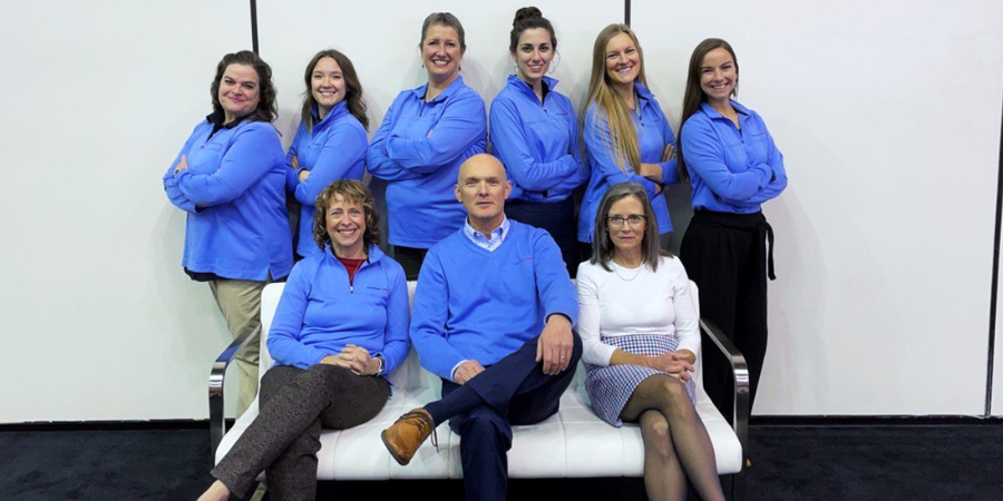
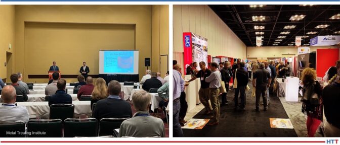
Furnaces North America 2022, the premier trade show and technical conference in the North American heat treating industry, attracted over 1,200 attendees from around the world. The show is produced by the Metal Treating Institute in partnership with its media partner, Heat TreatToday.
While attendees were in Indiana at the Indianapolis Convention Center, they experienced connection with 125+ top suppliers in the heat treating industry, 35 educational sessions in 10 tracks, and two packed social networking events.
Technical sessions and many exhibitors and attendees Source: MTI
Exhibitors and attendees alike contributed to the energy and quality of attendance on the show floor, with robust networking and connections flowing over the course of the three days. Topics that were top-of-mind included automation, labor shortages, and the current challenges with supply chain issues.
“When the show doors opened up, it was so exciting the see the reconnection of supplier and customer,” stated Tom Morrison, FNA show producer. “FNA is a big success because of a lot of people, including the Metal Treating Institute volunteers, sponsors, and management, who put their heart and soul into delivering a world class event. It was exciting to see that hard work payoff this week.”
FNA Show Management announced it will host FNA 2024 in Columbus, OH on October 14-16 at the Columbus Convention Center with the Hilton Columbus serving as the host hotel.
(Pictured above is the Heat Treat Today team left to right: Michelle Ritenour, Ellen Porter, Sarah Maffet, Bethany Leone, Lauren Porter, and Alyssa Bootsma; Karen Gantzer, Doug Glenn, and Mary Glenn)
Find heat treating products and services when you search on Heat Treat Buyers Guide.com
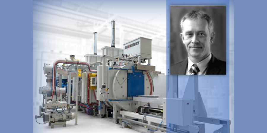
Modern industry trends and expectations pose new challenges to heat treating equipment; in addition to the expected requirements (e.g., safety, quality, economy, reliability, and efficiency), factors like availability, flexibility, energy efficiency, environmental, and the surrounding carbon neutrality are becoming increasingly important.
Maciej Korecki, vice president of Business Development and R&D at SECO/WARWICK, presents this special Technical Wednesday case study for the last day of FNA 2022 to focus on an equipment solution that meets these modern industry demands: a semi-continuous vacuum furnace for low-pressure carburizing (LPC) and high-pressure gas quenching (HPGQ).
Maciej Korecki Vice President of Business of the Vacuum Furnace Segment SECO/WARWICK
Introduction
At least 60 years ago, vacuum furnaces first appeared in the most demanding industries (i.e., space and aerospace), then spread to other industrial branches, and are now widely implemented in both mass production and service plants. Use of vacuum technology does not look like it is slowing down anytime soon.
Contact us with your Reader Feedback!
The driving forces behind this growth in vacuum technology are two-fold: first, the increasing heat treatment requirements that result from the directions of industrial development and production systems, and second, environmental protection, where the advantages of vacuum technologies are undeniable.
Traditional Atmospheric Technology
Case hardening by carburizing is one of the most widely used heat treatment technologies. It consists in carburizing (introducing carbon to the surface) followed by quenching of the carburized layer. Typically, the work is carburized in a mixture of flammable gases (CO, H2), and quenched in oil in an atmosphere furnace, using methods developed in the 1960s.
These methods have a history of development, though the question remains if the technological developments can keep up with the requirements of modern industry. Safety is an issue with this method due to the use of flammable (and poisonous) gases and flammable oil, as well as open flame, which in the absence of complete separation from the air can lead to fire, or poisoning.
In addition, they affect their environment by releasing significant amounts of heat, polluting the surroundings with quenching oil and its vapors. They require the use of washers and cleaning chemicals, emit annually tens or even hundreds of tons of CO2 (greenhouse gas, the main culprit of global warming and dynamic climate change) coming from the carburizing atmosphere, and for these reasons, they need to be installed in dedicated so-called “dirty halls” separated from other production departments.
The resulting requirement to limit the temperature of the processes to 1688-1706 oF (920-930oC) is also not without importance, as it blocks the possibility of accelerating carburization and increasing production efficiency (due to the use of metal alloys in the construction, the service life of which drops dramatically at higher temperatures) and the formation of unfavorable intergranular oxidation (IGO), which is a characteristic feature of the atmospheric carburizing method.
Quenching in oil is effective, but it does not have precise controllable, repeatable, and ecological features that heat treaters may need. Due to the multiphase nature of oil quenching (steam, bubble, and convection phase) and the associated extremely different cooling rates, it is characterized by large and unpredictable deformations within a single part and the entire load. Furthermore, there is no practical method to influence and control the quench process.
Modern Vacuum Technology with LPC and HPGQ
Vacuum carburizing appeared as early as the 1970s, but it could not break through for a long time due to the inability to control and predict the results of the process, and heavy contamination of the furnaces with reaction products.
The breakthrough came in the 1990s, when acetylene began to be used as a carbon-bearing gas and computers were employed to control and simulate the process. Since the beginning of the 21st century, there has been a rapid development of the low pressure carburizing (LPC) technology and an increase in its industrial demand, which continues today with an upturn.
Vacuum carburizing occurs with the aid of hydrocarbons (usually acetylene), which catalytically decompose at the surface, providing carbon that diffuses into the material. The process is carried out under negative pressure (hundreds of times less than atmospheric pressure) and is very precise, efficient, and uniform due to the very high velocity and penetration capacity of the gas molecules, allowing the carburizing of large and densely packed loads and hard-to-reach surfaces such as holes.
In addition, the use of non-oxygen-containing hydrocarbon atoms eliminates the qualitative problem of intergranular oxidation (IGO). The process is completely safe, there is no flammable or poisonous atmosphere in the furnace and no open flame, and the furnace can work unattended and is fully available and flexible, i.e., it can be turned on and off on demand, which does not require any preparation. Similarly, changing the carburizing parameters takes place efficiently.
Due to the design of the vacuum furnace and the use of materials with high resistance to temperature, i.e., graphite — the only limitation for the temperature of the carburizing process is the steel from which the parts are made — it is possible to carburize at higher temperatures than traditional methods allow. The result is a significantly shorter carburizing time and increased furnace efficiency versus what can be achieved in an atmosphere furnace.
Neutral gas cooling was included with the vacuum furnaces. Initially, engineers used a cooling gas (nitrogen or argon) at near ambient pressure and natural convection. Subsequent solutions introduced fan-forced gas flow in a closed circuit. The cooling efficiency under such conditions was hundreds of times lower compared to that of oil, allowing only high-alloy steels and parts with very limited cross-sections to be hardened. Over the following decades, the development of HPGQ was focused on improving cooling efficiency by increasing pressure and velocity and using different types of gas and their mixtures. Current systems have cooling efficiencies on a par with oil-based systems and enable the same types of steel and parts to be hardened, with the advantage that deformation can be greatly reduced and reproducible, and the process is completely controllable (through pressure and gas velocity) allowing any cooling curve to be executed.
Vacuum technologies have an ecological edge. Because of their design and processes, vacuum furnaces do not interfere with the immediate surroundings and are environmentally friendly, so they can be installed in clean halls, directly in the production chain (in-line). They emit negligible amounts of heat and post-process gases which are not poisonous and contain no CO 2 at all. Gas quenching eliminates harmful quenching oil and the associated risk of fire and contamination of the immediate environment, as well as the need for equipment and chemicals for its removal and neutralization. Nitrogen used for cooling is obtained from the air and returned to it in a clean state, creating an ideal environmentally friendly solution.
The presented advantages of vacuum technologies influence its dynamic development and increase the demand of modern industry, and the gradual replacement of atmospheric technologies.
Vacuum furnaces are available in virtually any configuration: horizontal, vertical, single, double, or multi-chambered, tailored to the process and production requirements. In light of recent global changes, requirements, and industrial trends, special attention should be paid to disposable, flexible, and rapidly variable production and process systems, as well as independent and autonomous systems, which include a three-chamber vacuum furnace for semi- continuous heat treatment, equipped with LPC and HPGQ.
Three-Chamber Vacuum Furnace — CaseMaster Evolution Type CMe-T6810-25
This is a compact, versatile, and flexible system designed for vacuum heat treatment processes for in-house and commercial plants, dedicated to fast-changing and demanding conditions in large-scale and individual production (Fig. 1). It enables the implementation of case hardening by LPC and HPGQ processes and quenching of typical types of oil and gas hardened steels and allows for annealing and brazing. It is characterized by the following data:
working space 610x750x1000 mm (WxHxL)
load capacity 1000 kg gross
temperature 2282oF (1250oC)
vacuum range 10-2 mbar
cooling pressure 25 bar abs
LPC acetylene gas
Installation area 8x7m
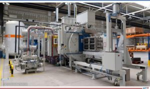
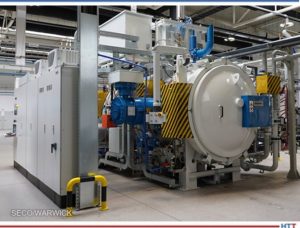
Fig. 1a. Furnace CMe-T6810-25.
Fig. 1b. Fig. 1. Furnace CMe-T6810-25. On the right – view from the loading side (pre-heating chamber), on the left – view from the unloading side (quenching chamber).
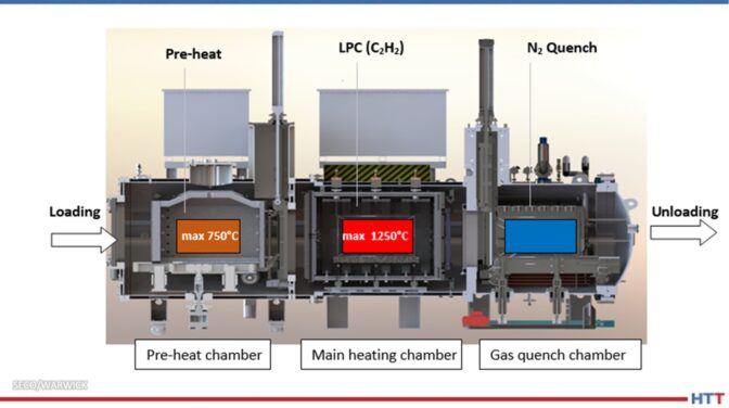
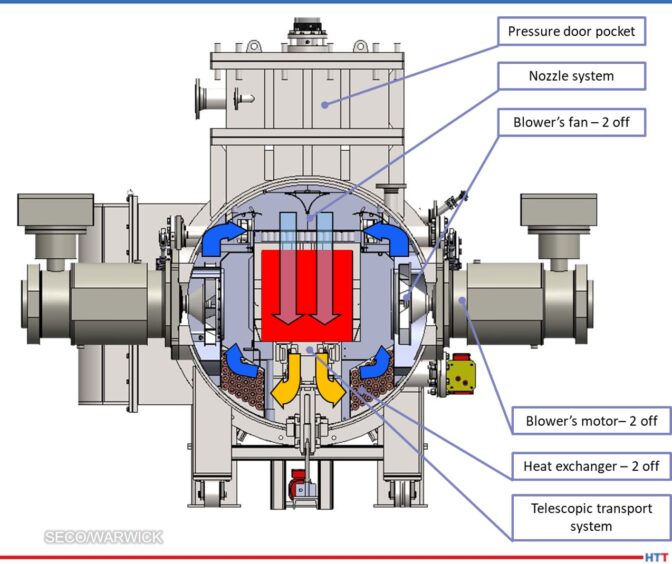
The furnace is built with three thermally and pressure-separated chambers (Fig. 2.), and operates in a pass-through mode, loaded on one side and unloaded on the other, simultaneously processing three loads, hence its high efficiency. The load is put into the pre-heating chamber, where it is pre-heated to the temperature of 1382oF (750oC), depending on the requirements: in air (pre-oxidation), nitrogen or vacuum atmosphere. It is then transferred to the main heating chamber, where it reaches process temperature and where the process is carried out (e.g., LPC).
In the next step, the charge is transported to the quenching chamber, where it is quenched in nitrogen under high pressure. All operations are automatic and synchronized without the need for operator intervention or supervision.
Fig. 2. Construction and schematic furnace cross-section CMe-T6810-25. Source: SECO/WARWICK
Particularly noteworthy is the gas cooling chamber, which in nitrogen (rather than helium) achieves cooling efficiencies comparable to oil (heat transfer coefficient >> 1000 W/m2K), thanks to the use of 25 bar abs pressure and hurricane gas velocities in a highly efficient closed loop system. The cooling system is based on two side-mounted fans with a capacity of 220 kW each, forcing with nozzles an intensive cooling nitrogen flow from above onto the load, then through the heat exchanger (gas-water), where the nitrogen is cooled and further sucked in by the fan (Fig. 3). The cooling process is controllable, repeatable, and programmable by gas pressure, fan speed and time. An intense and even cooling is achieved. The result is the achievement of appropriate mechanical properties of parts with minimal hardening deformations, without the use of environmentally unfriendly oil or very expensive helium.
Fig. 3. Cross-section of the furnace CMe-T6810-25 cooling chamber. Source: SECO/WARWICK
An integral part of the furnace system is the SimVaC carburizing process simulator, which enables the design of furnace recipes without conducting proof tests.
Distinctive Features of the CMe-T6810-25 Furnace
The advantages of this type of furnace — versus more traditional or past forms — can be demonstrated in a number of usability and functional aspects, the most important of which are the following:
Safety:
Safe, no flammable and poisonous atmosphere
No open fire
Production and installation:
Intended for high volume production (two to three times higher output when compared to single- and double-chamber furnaces)
Effective and efficient LPC (even five times faster than traditional carburizing)
Total process automation & integration
Clean room installation
Operator-free
Compact footprint
Quality:
High precision and repeatability of results
Uniform carburizing of densely pack loads and difficult shapes (holes)
No decarburization or oxidation
Elimination of IGO
Ideal protection and cleanliness of part surfaces
Accurate and precise LPC process simulator (SimVaC)
Quenching:
Powerful nitrogen quenching (neither oil nor helium is needed)
Reduction of distortion
Elimination of quenching oil and contamination
Elimination of washing and cleaning chemicals
Operational:
Flexible, on-demand operation
No conditioning time
No human involvement and impact
High lifespan of hot zone components — i.e., graphite
No moving components in the process chamber
Ecology:
Safe and environmentally friendly processes and equipment
No emission of harmful gases (CO, NOx, SOx)
No emission of climate-warming gas CO2
Based on the CMe-T6810-25 furnace performance, it is rational and reasonable to build heat treatment systems for high-efficiency and developmental production in a distributed system by multiplying and integrating further autonomous and independent units. The reasons for doing so are because the furnace design affords:
No risk of production total breakdown
Unlimited operational flexibility
Less initial investment cost
Unlimited multiplication
No downtime while expansion
Independent quenching chamber
Independent transportation
Independent control system
The characteristics, capabilities and functionalities of the CMe-T6810-25 furnace fit very well with the current and developmental expectations of modern industry and ecological requirements, which is confirmed by specific implementation cases.
Case Study
The three-chamber CaseMaster Evolution CMe-T6810-25 vacuum furnace was installed and implemented for production at the commercial heat treatment plant at the Polish branch of the renowned Aalberts surface technologies Group in 2020.
Fig. 4. Gearwheel used in the case hardening process. Source: SECO/WARWICK
The CMe furnace, together with the washer and tempering furnace, forms the core of the department's production, which is why the furnace is operated continuously. Last year, the furnace performed over 2000 processes and showed very high quality (100%) and reliability (> 99%) indicators. The very high efficiency of the furnace was also confirmed, which, with relatively low production costs, contributes to a very good economic result.
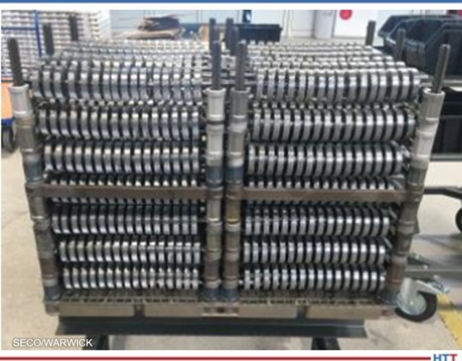
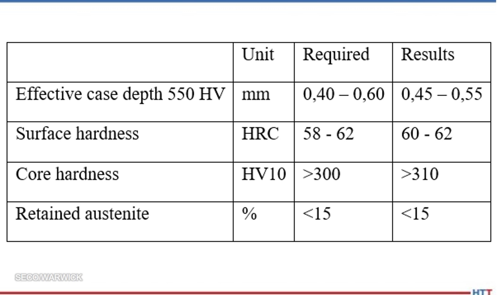
The case hardening process on gearwheels used in industrial gearboxes was taken as an example. The wheel had an outer diameter of about 80 mm and a mass of 0.52 kg (Fig. 4), and the load consisted of 1344 pieces densely packed in the working space (Fig. 5) with a total net weight of 700 kg (920 kg gross) and 25 m2 surface to be carburized. The aim of the process was to obtain an effective layer thickness from 0.4 – 0.6 mm with the criterion of 550 HV, surface hardness from 58 – 62 HRC (Rockwell Hardness C), core hardness at the gear tooth base above 300 HV10 and the correct structure with retained austenite below 15%.
Fig. 5. A photograph of the arrangement of gearwheels in the load. Source: SECO/WARWICK
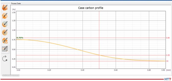
The LPC process was designed using the SimVaC® simulator at a temperature of 1724oF (940oC) and a time of 45 min, with 3 stages of introducing carburizing gas (acetylene), obtaining the appropriate profile of carbon concentration in the carburized layer, with a content of 0.76% C on the surface (Fig. 6).
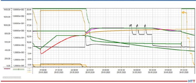
The process was carried out in the CMe-T6810-25 furnace and had the following course from the perspective of a single load (Fig. 7):
Loading into a pre-heating chamber, heating and temperature equalization in 1382oF (750oC) (100 min in total).
Reloading to the main heating chamber, heating and temperature equalization in 1724oF (940oC), LPC, lowering and equalizing the temperature before quenching in 1580oF (860oC), reloading to the cooling chamber (total 180 min).
Gradual quenching at a pressure of 24, then 12 and 5 bar, discharge of the load from a quenching chamber (total of 25 min).
Fig. 6. Carbon profile simulated by SimVaC®. Source: SECO/WARWICK
Fig. 7. Process flow in CMe® furnace parameter trends. Source: SECO/WARWICK
The load stayed the longest in the main heating chamber – for 180 minutes. This means that with the continuous operation of the furnace in this process, the cycle will be just 180 minutes, i.e., once every three hours the raw load will be loaded, and the processed load will be removed from the furnace.
In the next step, the parts underwent tempering at a temperature of 160oC.
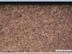
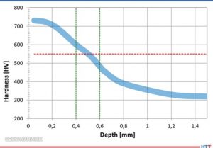
The result of the process was tested on ten parts taken from the reference corners and from the inside of the load. The correct layer structure (Fig. 8) and hardness profile (Fig. 9) were achieved, and all the requirements of the technical specification were met (Tab. 1).
Fig. 9. Hardness profile band obtained from tested gearwheels. Source: SECO/WARWICK
Tab. 1. Comparison of the parameters required and obtained in the process. Source: SECO/WARWICK
During the process, the consumption of the costliest energy factors was monitored and calculated, and the results per one load are as follows:
Electricity – 550 kWh
Liquid nitrogen – 160 kg
Acetylene – 1.5 kg
CO2 emissions – 0 kg
Cooling water and compressed air consumption have not been included as they have a negligible impact on process costs.
Summary: Efficiency and Economy
As a result of the process, all technological requirements have been met, obtaining the following indicators of efficiency and consumption of energy factors calculated for the entire load and per unit net weight of the load (700 kg):
On this basis, it is possible to estimate the total cost of energy factors in the amount of approximately EUR 100 per load or approximately EUR 0.14/kg of net load (assuming European unit costs of 2021). It is important that these costs are not burdened by CO2 emission penalties, as can happen with more traditional furnaces.
To sum up the economic aspect, based on an example process, a CMe furnace capacity of 1,500 net tons of parts per year was achieved for 6500 hours of annual furnace operation, at a cost of energy factors of about 100 EUR per load, or 0.14 EUR per kg of parts. The economic calculation is very attractive, and the return on investment (ROI) is estimated at just a few years.
Conclusion
While the advantages of this type of vacuum application are clear from this case study, the example discussed here does not represent the full capabilities of the CMe-T6810-25 furnace, even this process can be optimized and shortened, thereby increasing the furnace's efficiency, and reducing costs. It is possible to carry out carburizing processes (LPC) or hardening alone in a 1.5 h cycle, which would double the capacity of the furnace and similarly reduce the cost of energy factors and shorten the ROI time.
Getting excited for the November print edition? In 2021, Heat Treat Today released the inaugural Vacuum Heat Treating print edition. This edition is set to release every November to help heat treaters better work their vacuum furnaces and vacuum heat treat processes.
This Technical Tuesday original content round-up shares the hottest vacuum heat treating articles from this past year as you bundle up for the cool weather this fall. Enjoy!
Graphite in Vacuum Furnace Fixturing
Let's talk about carbon/carbon composite --- C/C.
Why is the vacuum furnace industry excited about its use in graphite vacuum furnace fixtures, grids, and leveling components? Because it can be readily machined for special shapes and applications. The lighter-weight material is mostly composed of carbon fibers and a carbon matrix (or binder).
Contact us with your Reader Feedback!
As the authors of this article explain, "They are among the strongest and lightest high temperature engineered materials in the world compared to other materials such as basic graphite, ceramics, metal, or plastic. C/C composites are lightweight, strong, and can withstand temperatures of over 3632°F (2000°C) without any loss in performance." Intrigued, are you not?
Step-by-Step Guide To Choose Heat Treating Equipment (English / Español)
If it's time to choose an industrial furnace, let's break it down step by step:
Step One: Quote Request
Step Two: Supplier Selection
Step Three: Study and Evaluation of Offers
Step Four: The Price
Follow this guide and avoid saying things like "The substation and/or the cooling tower did not have the capacity"; "The equipment is not what we expected"; or “They never told us that the furnace needed gas in those capabilities." If there are steps you take when selecting an industrial furnace, let us know in a Reader Feedback note here.
Pressure vs. Velocity and the Size of Your Furnace
If you like the R&D world of heat treat, but also like to be grounded in practical heat treat solutions, this is the article for you. Read about what this commercial heat treat found out about how size relates to the pressure and velocity of vacuum furnace cooling rates. Here are the facts you will learn:
The greatest impact on the cooling performance in a vacuum furnace is to increase the___ ______ within ___ _____.
This is achieved by ______ __ ______ of the ______ ____.
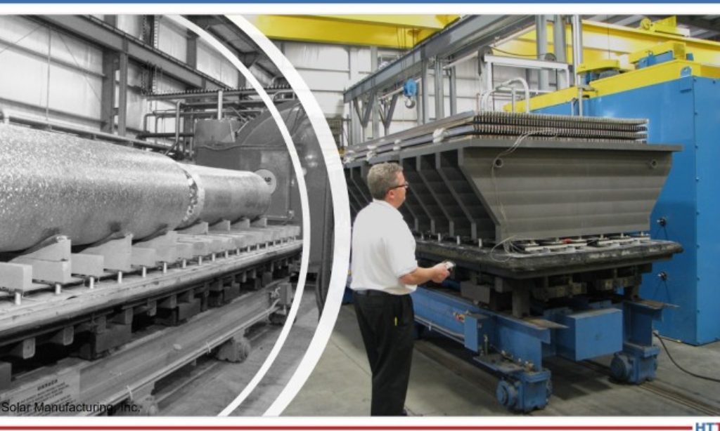
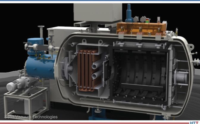
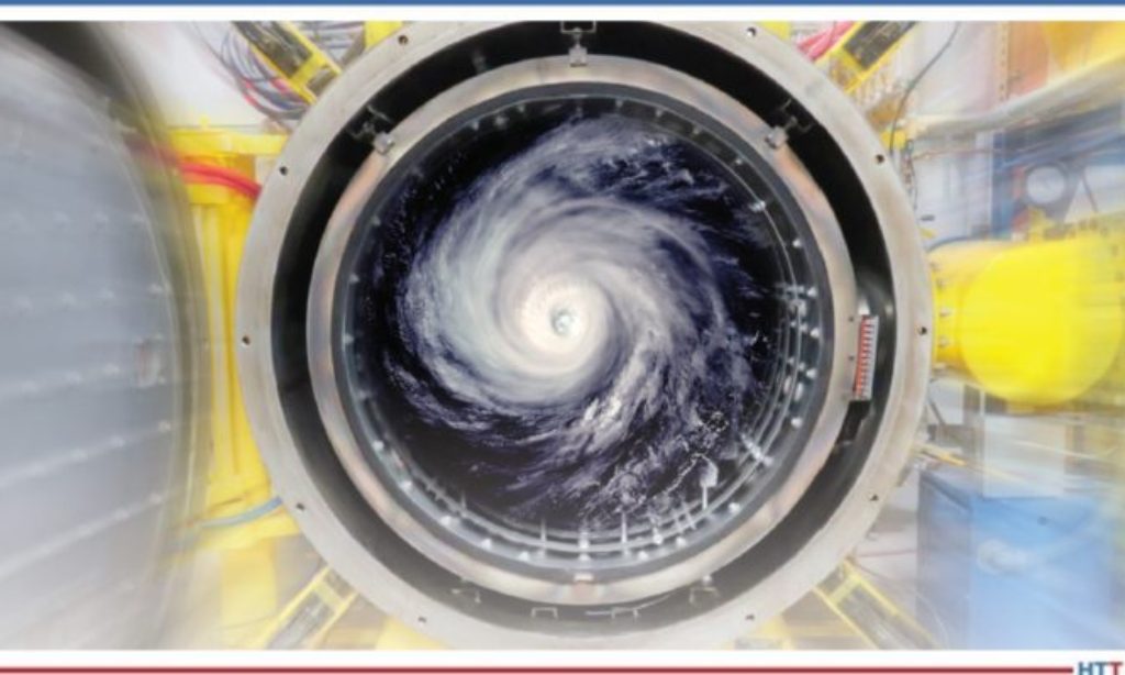
Energy at Large: A Heat Treat Vacuum Furnace Case Study
If you like to read about how heat treaters can be game changers in multinational science projects, this is the article for you. A specially designed vacuum heat treat furnace was commissioned to heat treat critical components in a large energy generator. The heat treating of these components takes 5 weeks to complete; talk about a long, uniform heat treat period.
Read about the energy experiment, the heat treat furnace, and the heat treating process in this technical feature.
[Está] posicionado no solo para trabajar en conjunto con otros seres humanos sino también para liderarlos; si su potencial se ha de realizar, puede que ya haya entendido bien que en esas personas reposa la verdadera clave del éxito que a futuro pudiera conseguir.
Bill Munn, coach de liderazgo at Bill Munn Management Coaching, wrote this article for Heat TreatToday’s September 2022 Tradeshowprint edition. Read the English translation when you click the flag to the right!
Bill Munn Leadership Coach Bill Munn Management Coaching Source: Bill Munn Management Coaching
¡Felicitaciones a Los 40 sub-40 de Heat Treat Today Promoción 2022! (En inglés: Heat Treat Today’s 40 Under 40 Class of 2022, N. del T.) Este galardón constituye un honor que señala a quien lo recibe como portador de una muy importante y singular responsabilidad.
Contact us with your Reader Feedback!
Usted es un líder.
Por definición, de aquí se desprende que no se desempeña solo; es más, está posicionado no solo para trabajar en conjunto con otros seres humanos sino también para liderarlos; si su potencial se ha de realizar, puede que ya haya entendido bien que en esas personas reposa la verdadera clave del éxito que a futuro pudiera conseguir.
¿Cómo, pues, lograr su compromiso?
✔ Primer paso: Afiance en sí mismo un espíritu enseñable, asumiendo su rol con la humildad sufi ciente como para buscar el consejo, la claridad y el aprendizaje continuo.
✔ Segundo paso: Aprenda cómo motivar a las personas.
Los tres pilares para motivar a un equipo
Luego de más de cinco décadas de trabajar de cerca con centenares de líderes excelentes junto con sus equipos, he identifi cado y confi rmado vez tras vez que hay tres factores claves para motivar el compromiso y el desempeño de las personas: la visión, la autonomía y el crecimiento.
Visión
Las personas anhelan ser parte de algo importante.
Desean que su actividad tenga significado. Ansían no solo entender la visión del equipo y la empresa a la que pertenecen sino también creer en ella.
Para generar tal visión no hace falta que usted esté dedicado a salvar el mundo. Bastará con que dedique un tiempo a revisar los valores fundamentales de su organización preguntando: <<¿Qué hace que esto sea importante? ¿Qué es imprescindible para que estemos aquí haciendo lo que hacemos?>>, para luego comunicar ese mensaje a su equipo.
Este es un proceso tan poderoso como esencial, uno que demasiadas veces se ha pasado por alto.
Autonomía
Las personas rechazan fuertemente la microgestión. Corresponda o no a la realidad, la microgestión transmite dos mensajes fatales para la motivación: <<No confío en usted>> y <<Creo que usted es incompetente>>.
Por otro lado, el asignar tareas a los miembros del equipo invitándolos a formular preguntas y despejar dudas para luego entrar con fuerza a desempeñarse por sí solos comunica todo lo contrario dando a entender: <<Confío en usted>> y <<Creo lo puede hacer>>.
Motiva de manera increíble.
Ganancia adicional: Los miembros de su equipo aprenderán y crecerán de forma más ágil, logrando un mayor alcance, cuando se les permita el desarrollo autónomo; demostrarán mayor sentido de pertenencia a la organización y su visión.
En pocas palabras, serán más comprometidos y efi caces.
Crecimiento
Las personas anhelan que se les haga progresar; quieren sentir, a lo largo de sus vidas y sus carreras, que están en vías de mejora y crecimiento, perfeccionando cada vez más su quehacer.
El personal suyo desea recibir retroalimentación, asistir a seminarios, participar en programas de formación, leer revistas informativas de peso como esta, y tener acceso a la ayuda, la asesoría y el desarrollo en su esfera particular.
Son demasiados los líderes que se acercan al personal para decir: <<deberías ser mejor en X o te falta avanzar en Y>> sin brindarles el apoyo
para lograrlo, comunicando así el no querer invertir en el éxito a largo plazo de esa persona, lo que a su vez genera que la persona invierta menos de sí en la organización y sus metas.
Si busca un equipo conformado por personas valiosas, apoye a esas personas en su crecimiento demostrando así que son valoradas.
Los resultados de una motivación efectiva
Un equipo motivado se compromete, y un equipo comprometido logra lo propuesto. Como líder de alto potencial usted tiene una oportunidad singular para encender en el personal con el que trabaja una llama, proceso que revertirá en benefi cio de sus metas propias.
Establezca la visión. Libere la autonomía. Fomente el crecimiento. Hacerlo se ha convertido ahora en su responsabilidad y un alto honor, honor que tanto su personal como su carrera le habrá de agradecer.
Le deseamos lo mejor. HTT
Sobre el Autor: Acerca del autor: Mediante el desarrollo de la visión estratégica y la resolución de retos en tiempo real, Bill Munn asiste a los ejecutivos en potenciar al máximo sus equipos. Desde su experiencia como veterano de 32 años en coaching empresarial y otrora ejecutivo destacado del Dow 30, Bill viene aportando sabiduría práctica, perspicacia innovadora y herramientas para el actuar contemporáneo a centenares de líderes corporativos a nivel mundial. Magister en administración de empresas y en su momento profesor de fi nanzas y economía, Bill es un conferencista dinámico y autor de best-sellers en Amazon.
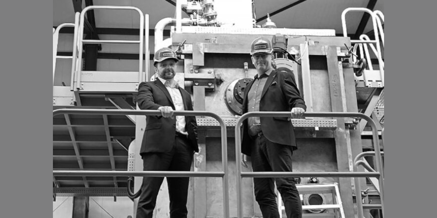
Sometimes our editors find items that are not exactly "heat treat" but do deal with interesting developments in one of our key markets: aerospace, automotive, medical, energy, or general manufacturing. To celebrate getting to the “fringe” of the weekend, Heat TreatToday presents today’s Heat Treat Fringe Friday press release: an agreement between GreenIron and SECO/WARWICK for a reduction furnace line will allow for the recycling of oxidized metals without emissions.
Swedish company GreenIron H2 AB has signed an agreement with the SECO/WARWICK Group, a global manufacturer of metal treatment equipment, for the delivery of a series of furnaces for fossil-free metal production including ore, residuals, and waste recycling.
Edward Murray CEO GreenIron Source: LinkedIn
"We feel that our partnership is a great foundation for rapid growth and a positive impact on emissions and climate change," commented Edward Murray, CEO of GreenIron. "GreenIron has high ambitions in regard to CO₂ reduction, starting with the first furnace, delivered by SECO/WARWICK, and the subsequent first shipment of commercial fossil-free iron in 2023."
The furnaces ordered by GreenIron will be used to recycle oxidized metals without emissions. They will therefore directly contribute to CO₂ emission reduction as each furnace has the capacity to reduce emissions by 56.000 metric tons/yr. The technology will help many enterprises implement "green" solutions and function in harmony with the natural environment.
Sławomir Woźniak CEO SECO/WARWICK Source: secowarwick.com
The metals are extracted from ore or recycled without the release of fossil gases. Iron oxide (magnetite, hematite, wustite) is converted to pure iron by the hydrogen reduction process. In traditional technology, this process takes place in coke furnaces, which results in CO₂ emissions. In the GreenIron furnaces, CO₂ emissions are zero.
“It is also an opportunity for SECO/WARWICK, because together with GreenIron we are creating a production line of completely new furnaces. For the first time, we are working closely with an external partner with technology that comes from outside of our organization,” adds Sławomir Woźniak, CEO of SECO/WARWICK Group.
Reduction furnaces will be available to companies throughout the entire lifespan of iron and other metals – including mining, steelmaking, milling stations, foundries, metal workshops and heavy ashes from incinerators.
Find heat treating products and services when you search on Heat Treat Buyers Guide.com


 The shale revolution (mostly happening in America) is the world’s biggest energy revolution. From 2005-2020, the amount of energy provided from shale was TWICE the amount of energy produced from wind and solar arrays combined. This is the largest increase in energy supply in the history of the world, anytime, anywhere. The next closest “revolution” was the Saudi oil fields, but the shale fields have produced nearly DOUBLE the amount of energy.
 The shale revolution (mostly happening in America) is the world’s biggest energy revolution. From 2005-2020, the amount of energy provided from shale was TWICE the amount of energy produced from wind and solar arrays combined. This is the largest increase in energy supply in the history of the world, anytime, anywhere. The next closest “revolution” was the Saudi oil fields, but the shale fields have produced nearly DOUBLE the amount of energy.
 Find heat treating products and services when you search on Heat Treat Buyers Guide.com


 If you like to read about how heat treaters can be game changers in multinational science projects, this is the article for you. A specially designed vacuum heat treat furnace was commissioned to heat treat critical components in a large energy generator. The heat treating of these components takes 5 weeks to complete; talk about a long, uniform heat treat period.