A domestic steel producer and metals recycler chose Sinton, Texas, as the site for the company’s new electric-arc-furnace (EAF) flat roll steel mill.
Steel Dynamics, Inc., a carbon steel producer which also owns Vulcan Steel Products that services the heat treat industry, recently announced its preferred choice as the Sinton location, 30 miles northwest of the port of Corpus Christi, Texas, because it is strategically located within the targeted Southwest U.S. and Mexico market regions; it’s central to the largest domestic consumption of flat roll Galvalume® and construction painted products; and it provides sufficient acreage to allow customers to locate on-site, providing steel mill volume base-loading opportunities.
Mark D. Millett President and CEO Steel Dynamics, Inc.
“We have been developing a flat roll steel business strategy for this region and Mexico for several years,” said Mark. D. Millett, President and Chief Executive Officer, “and the team is ready to execute. We have extensive experience and a proven track record for successfully constructing and operating EAF steel mills and downstream value-add finishing lines. Our planned new EAF flat roll steel mill will be the most technologically advanced facility existing today.”
READER QUESTION: Just read your article in regards to system accuracy test. I just had a question that maybe you can help me understand. When applying the correction factor of the test instrument and test sensor, is the correction factor to be used based on the furnace set point (operating temperature) at the time of the test or the recording instrument reading during the test? Any insight is appreciated!
This is a question that comes up often in the pyrometry courses I teach.
The Nadcap Pyrometry Reference Guide, question #6, addresses this question, although from a TUS standpoint. The premise is the same for the SAT process though.
Correction factors applied to any test results (TUS & SAT) should be determined based on the setpoint temperature during testing.
One thing to remember is that you may be testing at a temperature which does not fall directly at a temperature indicated on the test wire/test instrument calibration certificate. In this case, you would have two options;
1) Linear Interpolation
2) Pick the adjacent calibration temperature closest to your setpoint during test.
Either way, you would need to establish if you execute #1 or #2 above and document that in an internal procedure.
READER QUESTION: Thanks for the feedback, I have another concern. I perform an SAT on a refrigeration unit that operates at -20 degrees. My test instrument and test sensor are both calibrated at a low temperature of -20, but sometimes the recording instrument indicates a temp of -21 degrees or so. My operating temperature is -20 (setpoint), but as I stated it might indicate a lower temperature. Is there a possible finding here? Although setpoint is -20, recorder shows -21, which the test instrument/sensor does not cover (calibration point).
Jason Schulze for HTT:
You should be in no danger of a finding. The pyrometry guide states the correction factors are based on setpoint.
We welcome your inquiries to and feedback on Heat Treat Today articles. Submit your questions/comments to editor@heattreattoday.com.
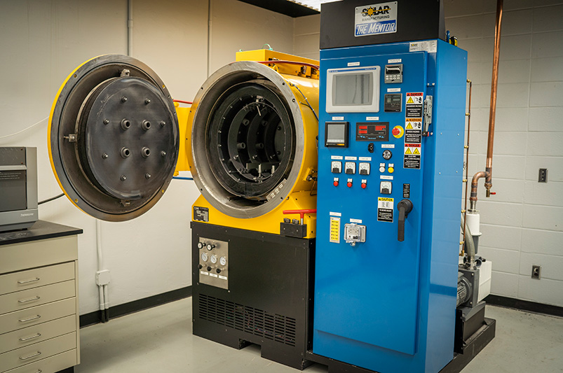
A thermal processing company donated a $300,000 commercial-grade vacuum heat treating and brazing furnace to Lehigh University’s materials science program to help increase opportunities for its students in the field.
The new addition, known as The Mentor®, was donated to Lehigh University by thermal processing company Solar Atmospheres and its CEO and founder, William R. Jones. Its sister company, Solar Manufacturing, designs and builds vacuum furnaces at its location in Souderton, Pennsylvania, just 23 miles from Lehigh’s campus.
Additionally, Solar Atmospheres built and donated a transformer and water-cooling system that was specifically designed for the application.
Wojciech Misiolek, professor and cha ir of the Department of Materials Science and Engineering at the P.C. Rossin College of Engineering and Applied Science
“This is a very powerful, advanced piece of equipment that will allow us to conduct important experiments in our metallurgy teaching and research, especially around additive manufacturing, which is a hot topic these days,” explains Wojciech Misiolek, professor and chair of the Department of Materials Science and Engineering at the P.C. Rossin College of Engineering and Applied Science. “And we will challenge ourselves to use it up to its full capabilities for heat treatment of metals.”
“With this donation,” adds Misiolek, “suddenly you have the industry-grade equipment. It’s not a miniature version, it’s what you will see out in the field. Our educational system at Lehigh is very hands on, and we have a reputation for that. This furnace will increase opportunities for our undergraduate and graduate students and help them hit the ground running when they go into industry.”
Induction heat treaters know that proper coil design is crucial to increasing longevity, improving production quality, and cutting costs. Among the topics addressed in this paper about induction heat treat coil design and fabrication (presented by R. Goldstein, W. Stuehr, and M. Blackby at ASM International) are these:
The design and fabrication of induction heating coils over the years
The Variable of Flow and the Influence of Frequency
Control and Presentation
Structure, Quenching, and Cooling
The paper closes out with a case study using computer simulation to show typical temperature distributions in a single-shot induction hardening coil.
A good place to start whenever preparing parts for induction heat treating is the consideration of inductor design. The authors provide this list (an excerpt):
[spacer color="264C84" icon="Select a Icon"]
Considerations for Inductor Design
Induction heat treating coils are available in many shapes and sizes and must perform a variety of tasks in a given induction heat treating application. Depending on the application, the induction coil design requirements include:
Meet heat treatment specifications in desired production rates
Be robust enough to tolerate manufacturing variations
Mount into the induction machine
Have electrical parameters that match the induction power supply
Deliver quench
Have a satisfactory lifetime
Have satisfactory efficiency
Be repeatable from inductor to inductor
In developing a new induction heat treating coil and process, the first question is whether the component will be produced on an existing system or if a new machine must be built. In many cases, the part producer’s desire is to develop new tooling for an existing machine with spare capacity. This reduces the degree of freedom and can make the induction coil design procedure more complicated because a less-than-optimal frequency or coil style will be necessitated to fit the existing machine (Ref 16).
To determine the ability to use existing equipment, it is necessary to make an analysis of the part to be heat treated. Part material, prior processing, geometry, production rate, and heat treatment specifications all play roles. The part material and prior processing determine what the minimum heat treatment temperature should be, along with how much time is allowed for cooling. The part geometry and heat treatment specifications indicate how much energy is required, what the preferred frequency ranges are, and what type of induction method (i.e., single shot, scanning) is best suited for the application. Finally, the production rate determines how much power and/or how many spindles or stations are required.
Heat Treat 2019 is coming, and one of the great benefits of gathering with a community of heat treaters is the opportunity to challenge old habits and look at new ways of doing things. Heat TreatToday’s101 Heat TreatTips is another opportunity to learn the tips, tricks, and hacks shared by some of the industry’s foremost experts. The inaugural list of 101 Heat Treat Tips was published in the FNA 2018 Special Print Edition. This special edition is available in a digital format here.
Today's Technical Tuesday features 10 Tips -- all from the Vacuum Furnaces category and all supplied by the same equipment manufacturer.
Heat TreatTodayis compiling the 2019 101 Heat TreatTipslist for the fall issue to be distributed at Heat Treat 2019, the biennial show from the ASM Heat Treating Society to be held in Detroit, Michigan, October 14-17, 2019. If you have a heat treat-related tip that would benefit your industry colleagues, you can submit your tip(s) to doug@heattreattoday.com or editor@heattreattoday.com.
Heat TreatTip #24
Dirt In, Dirt Out!
Parts going into the furnace should be as clean as possible. Avoid placing parts in the furnace that contain foreign object debris (FOD). FOD on work surfaces going into the furnace will contaminate the furnace and the parts themselves. Dirty work in, dirty work out. FOD comes in many forms. Most common: oil, grease, sand in castings or grit blasting operations, and metal chips that generally originate from the manufacturing process before the parts are heat treated. It could also be FOD from the shipping process such as wood or plastic containers used to ship the parts.
Heat TreatTip #26
Solenoid valves could be the problem if helium detection fails.
When a Helium Leak Detector Doesn't Help
If an air leak cannot be found with a helium mass spectrometer, take apart the gas backfill or partial pressure solenoid valves to ensure they are clean. A small piece of debris can cause a valve to leak a process gas into the furnace that will not be found with a leak detector. Debris is often found in the valve seats when piping to the valve was disturbed in some way such as new piping or repair that stirs up contaminants in the line.
Heat TreatTip #46
O2 Analyzer Helps Ensure Gas Purity
In addition to monitoring dewpoint at the farthest location from the gas source in your heat treat facility, an oxygen analyzer is also recommended as an additional tool for monitoring gas purity. Generally, the analyzers used to measure dew point drift low over time. One may think they have a very low dew point gas, however, it could be the dew point analyzer is beginning to fail. Quarterly checks of the dew point analyzer's accuracy should be taken; some OEMs recommend replacing the sensors annually. Oxygen analyzers provide a more stable reading over a period of time and build redundancy in confirming gas purity when coupled with the dew point analyzer.
Heat TreatTip #48
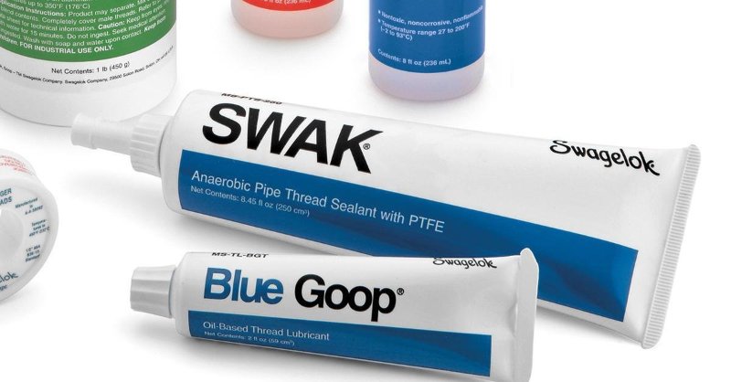
Seal Threaded Connections
SWAK from Swagelok is a great thread sealing option. (photo source: LinkedIn)
Ensure threaded connections have adequate sealing protection on them to prevent air leaks through the threads where applicable. Wipe off excess sealant once the connection is made.
SWAK from Swagelok is excellent
Apply to the male threads only, not on any other surface as it could contaminate the system the component is being installed on.
Excess SWAK can be removed with a solvent such as acetone
Finger tight first, then tighten with a wrench
After the sealant is dry (recommend 24hrs by manufacturer) do not loosen as this could break the seal once cured.
Heat TreatTip #61
Start With the Obvious
When a problem arises with the furnace, always start the troubleshooting process with the last item that was worked on. Start with the obvious; don't look for a needle in the haystack. For example, if the furnace will not pump into high vacuum and maintenance was just performed on the furnace with the pneumatic pressure valves being shut to perform that maintenance operation, the pneumatic valve to the main poppet valve on the diffusion pump may not have been re-opened, causing the diffusion pump main poppet valve to not open.
Heat TreatTip #74
Make Sure Your Gas Meets Spec
Ensure each delivery of process gas is accompanied by a certification identifying purity, oxygen content, and dew point. For example, nitrogen should be 99.998% pure, 10 ppm oxygen max, and a dewpoint no higher than -89°F. With contaminated gas or gas that does not meet the criteria above, parts processed in the furnace and subjected to the partial pressure of the gas or quenched with the gas may also become contaminated, typically in form of oxidation and/or decarburization. Generally varying purity is not a concern, however, the specific purity of the gas required needs to be conveyed to the gas supplier and a certification supporting the gas type you ordered was delivered. An accompanying certification by the gas supplier goes a long way in audits and other disputes.
Heat TreatTip #76
Specification Checklist for Vacuum Furnace Purchase
If you're planning on purchasing a new vacuum furnace, create a technical specification for the manufacturer(s) that clearly outlines the performance, functions, and accessories required on the furnace. The specifications should be reviewed by multiple departments including but not limited to engineering, quality, production, and management.
List of department sign-offs required (engineering, production, maintenance, quality)
List of parameters to be recorded (temperature, pressure, flow rate, etc.)
List of required alarms
Physical location of furnace and associated components such as control system and surge tank
Units of measurement (°F or °C, torr or Pascals, minutes or hours)
How many process gases and what type
Cooling rate requirements (This will help decide what quench pressure design furnace is required, for example, 2 bar or 10 bar.)
How many work thermocouples are required
What pre-testing verification is required for final acceptance. For example, thermal uniformity survey temperature points and tolerances, vacuum pump downtime and levels, leak up requirements, quench tests, process validation tests.
Wipe both door flanges and O-ring every time.
Heat TreatTip #84
Clean the Door—Every Time!
Wipe down the front door O-ring and both flanges every time before the door is closed to ensure there is no debris on the O-ring or flange. Over time, the debris will damage the O-ring and pit the flange causing sealing issues.
Heat TreatTip #91
Include Maintenance Team in New Vacuum Purchase Process
Include the maintenance manager in any furnace purchase decision. The manager and team are the ones tasked with troubleshooting, repair, and preventative maintenance. The maintenance manager will make sure the furnace has clear access for maintenance and replacement of major components including vacuum pumps, cooling motor, hot zone, and heat exchanger. The longer it takes to repair the furnace, the more downtime and lost revenue because the furnace is not running.
Heat TreatTip #94
A properly greased O-ring will ensure a solid, leak-free seal.
Inspect Replacement O-Rings
When replacing an O-ring, be sure the new O-ring is clean and undamaged (free of cuts, nicks, tears, or gouges) and that the splice joint is solid and true. Use a conservative amount of vacuum grease on the O-ring to ensure a tight sealing furnace. Not too much grease is needed. Rule of thumb: a light gloss or sheen, but no build-up.
If you have a heat treat-related tip that would benefit your industry colleagues, you can submit your tip(s) to doug@heattreattoday.com or editor@heattreattoday.com
A North American manufacturer of powder metal products recently announced plans to expand its Pennsylvania facility, adding new production capabilities to support additive manufacturing and other technologies.
Photo: Daily American
North American Höganäs High Alloys, founded in 1896 in Johnstown, Pennsylvania, will construct a 24,000-square-foot building this location and purchase new machinery to support the global demand for high alloy products, which include stainless steel powders, iron alloy powders, nickel alloy powders, electrolytic iron powders and chips, manganese and silicon powders, and the proprietary GLIDCOP dispersion strengthened copper products.
Linda R. Thomson, president and CEO of the non-profit economic development organization JARI
“Pennsylvania’s powder metals industry is a major contributor to our manufacturing sector,” said Pennsylvania Governor Tom Wolf. “Höganäs’ decision to expand here is great news for Pennsylvania manufacturing, and will provide at least 25 reliable, family-sustaining jobs for Cambria County workers.”
“JARI is pleased to provide support to Höganäs as the company expands their operations in the City of Johnstown,” said Linda R. Thomson, president and CEO of the non-profit economic development organization JARI. “Höganäs is a world-class, internationally recognized company with state-of-the-art products that is meeting the demands of the new manufacturing age. We appreciate the continuation of the proud Cambria County tradition of leading the way for innovation and we thank the Wolf Administration for their continuous support.”
“This exciting investment, with the greatly appreciated support from the Governor’s Action Team and JARI, will help Höganäs continue to grow in Pennsylvania and provide innovative products for our customers in several quickly developing market areas,” said Dean Howard, President Americas Continent.
This article continues the ongoing discussion on Equipment Selection for Induction Hardening by Dr. Valery Rudnev, FASM, IFHTSE Fellow. Six previous installments in Dr. Rudnev’s series on equipment selection addressed selected aspects of scan hardening and continuous/progressive hardening systems. This post continues a discussion on equipment selection for induction hardening focusing on single-shot hardening systems.
The first part on equipment selection for continuous and progressive hardening is here. The second part in this series on equipment selection for single-shot hardening is here; the third part is here. To see the earlier articles in the Induction Hardening series at Heat TreatTodayas well as other news about Dr. Rudnev, click here. This installment continues a discussion on equipment selection for continuous and progressive hardening applications.
Why Single-Shot Hardening?
With the single-shot method, neither the workpiece (cylinder shaft, for example) nor the coil moves linearly relative to each other; the part typically rotates instead.¹ The entire region that is to be hardened is heated all at once rather than only a short distance, as is done with scan hardening.
With conventional scan hardening of cylindrical parts, induced eddy currents flow circumferentially. In contrast, a single-shot inductor induces eddy currents that primarily flow along the length of the part. An exception to this rule would be the half-moon regions (also called the crossover or bridge sections) of a single-shot inductor, where eddy current flow is circumferential.
Normally the single-shot method is better suited for hardening stepped parts where a relatively short (1.5–2 in. [38–50mm] long heated area is commonly minimum) or moderate length area is to be heat treated. This method is also better suited to cylindrical parts having axial symmetry and complex geometry including various diameters.
When scanning these types of parts, improper austenitization of certain areas may occur due to localized electromagnetic field distortion, for example. Insufficient quenching due to the deflection of quench flow not allowing it to properly impinge on the surface in various diameter regions may also occur. Both factors are considered undesirable and can cause low hardness, spotted hardness, or even cracking. For example, the use of scan hardening on stepped shafts with large shoulders, multiple and sizable diameter changes, and other geometrical irregularities and discontinuities (including fillets, flanges, undercuts, grooves, etc.) may produce severely non-uniform hardened patterns. In cases like this, a scan hardening inductor or progressive/continuous hardening system would be designed around the largest diameter that would have sufficient clearance for safe part processing.¹ However, variations in the shaft’s diameter, to a significant extent, will result in a corresponding substantial deviation in the workpiece-to-coil coupling in different sections of the shaft, potentially causing irregular austenization.
Besides that, sharp corners have a distinct tendency to overheat owing to the buildup of eddy currents, in particular when medium and high frequencies are used. The electromagnetic end and edge effects may also cause the shoulders to severely overheat while the smaller-diameter area near the shoulder (including undercuts and fillets) may have noticeable heat deficit. These factors may produce a hardness pattern that might grossly exceed the required minimum and maximum case depth range, making it unacceptable. Single-shot hardening is usually a better choice in such applications. As an example, Figure 1 shows some examples of components for which single-shot hardening would be a preferable method of heat treating.
Examples of components for which a single-shot hardening would be a preferable method of heat treating. (Courtesy of Inductoheat Inc., an Inductotherm Group company)
In some not so frequent cases, when hardening larger parts, there are advantages to the single-shot method over the scanning method, such as the reduction of shape/size distortion, enhanced metallurgical quality, and increased production rate.
Single-shot hardening may also be the preferred choice when shorter heat times/high production rates are desired. For example, in some applications, the time of heating for single-shot hardening can be as short as 2 s, though 4 to 8 s is more typical.
However, the single-shot method has some limitations as well. One of them is cost. Single-shot inductors are typically more expensive to fabricate compared to the coils used for scanning. This is because the single-shot inductor, to some degree, must follow the contour of the entire region required to be heated. Additionally, a single-shot inductor is usually able to harden only one specific part configuration, whereas a coil used for scanning may be able to harden a family of parts.
Besides that, in some case hardening applications using a scanning method, it is possible to apply certain pre-programmed pressure/force on a workpiece during heat treating. This allows distortion to be controlled. Single-shot hardening might also permit applying this technique but there might be some limitations.
Design Features of Single-Shot Inductors
Single-shot inductors are made of tubing, either 3-D printed or CNC-machined from solid copper to conform to the area of the part to be heated. This type of inductor requires the most care in fabrication because it usually has an intricate design and operates at high power densities, and the workpiece’s positioning is critical with respect to the coil copper profiling. Figure 2 shows several examples of induction heating of different components using single-shot inductors.
Several examples of induction heating of different components using single-shot inductors. (Courtesy of Inductoheat Inc., an Inductotherm Group company)
In order to provide the required temperature distribution before quenching, heat is sometimes applied in several short bursts (pulse heating) with a timed delay/soaking between them to allow for thermal conduction toward the areas that might be difficult to heat.
Single-shot inductors typically require higher power levels than used in scan hardening because the entire area of the workpiece that needs to be hardened is austenitized at once. This is the reason why single-shot hardening normally requires having a noticeably larger power supply compared to scan hardening, resulting in increased capital cost of power source. Additionally, the increased power usage and power densities combined with complex geometry can reduce the life of the inductor. For this reason, single-shot inductors often have shorter lives than scan inductors.
It is always important to keep in mind that, electrically speaking, the inductor is typically considered the weakest link in an induction system. For this reason, most single-shot inductors have separate coil-cooling and part-quenching circuits. The inductor will fail if power is increased to the point at which the water cannot adequately cool it. Additional cooling passages may be needed with high-power density, single-shot inductors. A high-pressure booster pump is also frequently required.
The next several installments of Dr. Valery Rudnev on . . . will continue the discussion on design features of single-shot inductors and equipment selection.
In order to maintain the cleanliness of workpieces and baskets or fixtures in the vacuum heat treating or brazing process, it is helpful to establish a pre-treating cleaning practice. Vapor degreasing has emerged as a cleaning process with the acting principle that the solvents will dissolve the contaminants on the workpiece and remove them by dripping off the part. In this week’s Technical Tuesday article, a Best of the Web feature, we bring you an article from VAC AERO International addressing the development of the process, the steps involved in vapor degreasing, and comparisons with other cleaning methods.
Cleaning in a solvent offers a level of simplicity and forgiveness not seen in aqueous methods. At one time, solvent cleaning was considered mandatory for successful vacuum processing but environmental concerns (VOC and other emissions) and improvements to aqueous systems including drying technology has seen the industry shift to aqueous cleaning as the norm. Today, however, with the advent of vacuum technology, vacuum vapor degreasing has emerged as a viable alternative to aqueous processing.”
A preview:
Vacuum vapor degreaser schematic with operational sequence steps. (“Removal of Entrained Moisture from Powdered Metal Parts Using High-Temperature Solvent and Vacuum” PM2TEC 2003, via VAC AERO International)
Main image photo credit/caption: Vacuum Processing Systems LLC (via VAC AERO International) / Typical vacuum vapor degreaser
Dr. Mihails Scepanskis is the CEO and co-founder of CENOS LLC.
Induction heating is an efficient way to quickly heat electrically conductive metals with pinpoint accuracy. It starts very simply, with a coil of conductive material, however initial design and optimization of the process are very complicated—it's hard to predict power, frequency, and heating time to get necessary results.
Computer simulation for induction heating is a powerful tool that enables engineers to investigate or design a physical system and process using a virtual mathematical model, thus saving time and money on numerous physical design iterations.
Dr. Vadims Geza is the chief scientist at CENOS.
Induction heating computer simulation offers the most efficient means of developing customized and optimized solutions and is, therefore, a necessity—not a luxury—in the modern induction heating industry. In this article, Dr. Mihails Scepanskis and Dr. Vadims Geza, both of CENOS LLC, based in Riga, Latvia, list features and benefits, obstacles and solutions of induction heating; advantages and disadvantages of computer simulation vs physical testing; what should be taken into account when choosing the right simulation software.
How simulation software can help companies save time and money on induction coil and process design
About Induction Heating
Today induction heating is used in many industrial processes, such as heat treatment in metallurgy, crystal growth and zone refining used in the semiconductor industry, and to melt metals which require very high temperatures.
Where Is Induction Heating Used?
Automotive
Construction
Aerospace
Metallurgical Plants
Oil & Gas Component Manufacturing
Special Applications
NASA's experimental NTP fuel elements heated with induction (Photo: CENOS)
Features:
Heat generation occurs inside the part.
Heating is contactless—as a result, product warpage, distortion and reject rates are minimized.
This method can provide very high power densities.
Heating may be highly selective in the depth and along the surface.
Any processing atmosphere (air, protective gas, vacuum) can be applied.
Very high temperatures may be reached.
The general benefits of induction surface heat treatment are
Short heating times—production rates can be maximized.
Optimized consistency—induction heating eliminates the inconsistencies and quality issues associated with open flame, torch heating, and other methods.
Extended fixture life—induction heating delivers heat to very small areas of your part without heating any surrounding parts. This extends the life of the fixturing and mechanical setup.
Environmentally sound without burning fossil fuels—induction is a clean, non-polluting process. Improves working conditions for employees by eliminating smoke, waste heat, noxious emissions, and loud noise.
Effective energy consumption—this uniquely energy-efficient process converts up to 90% of the energy expended energy into useful heat; batch furnaces are generally only 45% energy-efficient. Requires no warm-up or cool-down cycle.
Flexible adaptation to the hardening tasks
Closed loop computerized process control and compatibility with overall process automation
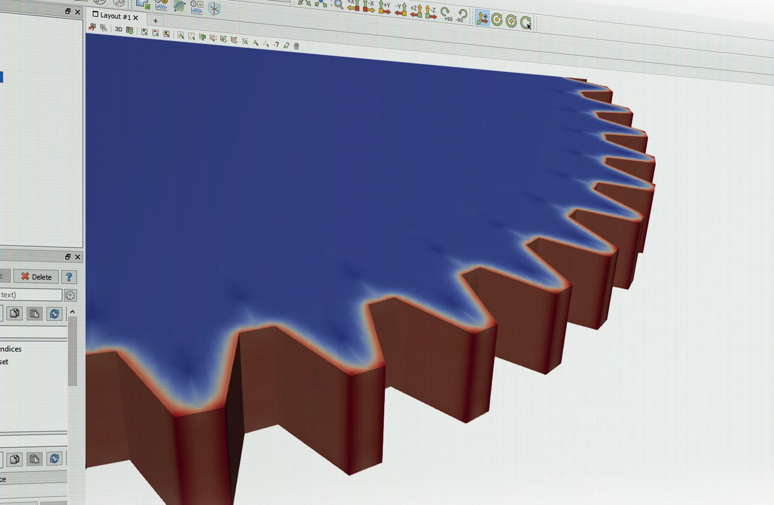
Large gear heat treatment (Photo: CENOS)
Obstacles:
Initial design and optimization of the process is very complicated.
It is hard to predict power, frequency and heating time to get necessary results.
Unlike other heating methods, induction heating requires specific coil design for each workpiece, so it's not very economic unless you need to process multiple similar workpieces.
To design and calculate the induction heating process you can:
Do a rough analytical estimation, then proceed with countless design iterations in the lab.
Find a professional company that can do induction coil and process design for you, but keep in mind that you most likely will be charged for design hours spent in the lab.
Buy a sophisticated multi-physics simulation software and hire a trained simulation engineer/analyst or pay for engineer's training (usually takes 3 months).
Start using a simple, affordable, and induction heating-focused simulation software like CENOS Platform, which features online training and templates for a quick and easy start.
Induction Heating and Computer Simulation
What Is a Computer Simulation?
Nowadays, in various industries, manufacturers prefer using software simulations over physical testing. Computer simulation is a powerful tool that enables engineers and scientists to investigate or design a physical system and/or process using a virtual mathematical model, thus saving time and money on numerous physical design iterations.
The vast majority of modern computer simulation software packages utilize numerical methods (e.g. finite element method or “FEM”) to evaluate extremely complex physical systems—systems that are otherwise impossible to precisely analyze. By leveraging the power of modern computer hardware, simulation software can provide substantial improvements in the efficiency, reliability, and cost-effectiveness in design and development processes.
Computer Simulation in Induction Industry
First works on computer simulation of induction coils were made in the 1960s. Due to limited access to computers, their low memory, speed, and poor programming methods, the computer simulation did not receive significant industrial application until the 1980s.
Now computer simulation has become a practical tool for everyday use in the induction industry. It allows the user to design optimal systems, improve equipment performance, dramatically reduce development time and costs, and better understand the process dynamics, etc.
Though there are still difficulties in an accurate simulation of non-linear and different mutually coupled tasks, computer simulation is effectively used for the design of induction heating coils and problem solution.
The 10 cm gear hardening with one concentric inductor at 170 kHz and 1.9 kA over 120 ms
Benefits and Value of Induction Heating Computer Simulation
The use of induction heating computer simulation software can promote substantial improvements in the performance and cost-effectiveness of induction heating equipment, in addition to large reductions in the cost and time required to design and develop induction heating processes.
From a design perspective, computer simulation is valuable for a number of reasons, two of the most notable being:
The physics involved in utilizing electromagnetic induction as a deliberate and controlled source of heat generation is extensive and multi-faceted. Computer simulation provides a quantitative approach to designing and developing induction heating processes, allowing complex physical phenomena that cannot be physically observed and/or measured to be clearly visualized and quantified.
Because electromagnetic induction offers an extremely effective, economical, and versatile means of heating conductive materials, the scope of induction heating applications is very broad. This includes (but is not limited to):
Furthermore, each of these general applications includes countless different workpiece types, geometries, materials, and heating requirements. As a result, no “universal solution” exists in the design of induction heating equipment. Induction heating computer simulation offers the most efficient means of developing customized and optimized solutions and is, therefore, a necessity—not a luxury—in the modern induction heating industry.
Combining Simulation With Real World Tests for the Best Results
Example of simulation results (Photo: CENOS)
Inductor design is one of the most important aspects of the overall induction heating system. A well-designed inductor provides the proper heating pattern for your part and maximizes the efficiency of the power supply, while still allowing easy insertion and removal of the part. With the right design, it's possible to heat conductive materials of any size and form, or only the portion of material required.
Computer Simulation vs Experimental Method
Computer Simulation
Advantages
Can work for any geometry and operating conditions
Demonstrates the entire dynamics of the process
Leaves records for future
Limitless accuracy of calculations
Does not require special equipment
Less expensive and less time-consuming
Future improvements expected
Provides 3D process visualization for customers (pictures, video)
Limits and Disadvantages
Requires special software and databases
Not all the processes may be simulated (as of today)
Does not provide physical samples
Experimental Method
Advantages
May provide the most reliable results
Can show the performance of the whole system including unexpected effects and troubles
Does not require a material property database
Provides physical samples for properties validation
Limits and Disadvantages
May require expensive equipment
Does not provide a good understanding of the process
Difficult to transfer knowledge (to scale a company)
Case dependent accuracy
Limited access to production equipment (expensive)
Time-consuming—may cause production delay due to multiple design iterations.
Challenges in coil design
The induction coil, also known as an "inductor", is essential to induction heating. Single-turn, flexible, multi-turn cylindrical, left-turn, right-turn, rod-shaped, hair-pin, parallel, ear-shaped, tiny, big—whatever the coil shape and size—the right design maximizes the lifetime of the coil and ensures lowest energy consumption and best effects on work process and materials.
Many factors contribute to a coil’s effectiveness: the care taken to make it, the quality of the materials used, its shape, its maintenance, its correct matching with the power source, etc.
Here are just three of the many hurdles to be overcome in order to make safe and efficient coils:
Impedance matching
It is necessary to achieve the correct impedance matching between the coil and the power source in order to use the latter’s full power. The coil designer must also consider that coils need five to ten times as much reactive as active power.
Magnetic flux concentrators
Concentrators focus the current in the coil area facing the workpiece. Without concentrators, much of the magnetic flux may propagate around the coil. This flux could engulf adjacent conductive components. But when concentrated, the flux is restricted to precise areas of the workpiece.
Water flow and speed
It is generally important to achieve an adequate flow of cooling water through the coil. When high power density is expected in the inductor, the coil designer must consider the flow rate and the water’s velocity. This is because velocity significantly influences the heat transfer between inductor and coolant and therefore has a major impact on the longevity of the coil. A booster pump is sometimes needed to maintain the desired flow and velocity. Professional designers will also specify a purity level for the water in order to minimize coil corrosion.
Tools and Processes Necessary To Ensure Coil Longevity and Performance
Advanced induction coil design includes:
Detailed analysis of specifications, available equipment, and environment
Coil style and heating process selection (scanning, single-shot, static, etc.)
3D design programs and computer simulation for coil head optimization
Analysis of benefits of magnetic flux controllers application
Advanced manufacturing techniques, mandrels to achieve tight tolerances
Testing in a laboratory or industrial plant for performance and final dimensional check
Final corrections if required
Designing and making induction coils is technically challenging. Computer simulation helps tackle some of the challenges, limiting costs and maximizing effectiveness.
CENOS Platform's mission is to help companies switch from old and cumbersome experimental methods to a powerful computer simulation that is simple, affordable, and induction heating-focused. CENOS, combined with real-world trials, will yield the best results in a fast and cost-effective way.
How To Choose the Right Simulation Software
The induction heating market is small compared to other industrial sectors, and there are only a few specialized simulation packages on the market that can be used for induction process and coil design. Induction heating simulation involves a set of mutually coupled non-linear phenomena. Many induction applications are unique and may require different program modules. In addition to computer simulation software, an extensive material database is necessary for accurate results.
1D, 2D or 3D?
Majority of practical simulations now are being made in 1D or 2D approaches. But with 1D and 2D, the structure and geometry of real induction systems are often very simplified. In reality, a majority of induction systems are 3D. In addition, interference of induction device and source of power must be considered in many cases. That's why 3D will ensure less space for errors and a more thorough analysis.
Cloud vs Desktop
Working with cloud-based software requires uploading your data to the third party. Frequently induction heating equipment manufacturers are not allowed to share their customer CAD files with a third party due to NDA. Furthermore, while cloud computing may provide increased calculation speed, one should consider the time it takes for uploading the design files and downloading the result files.
Importance of training & support (time, costs)
There is a common opinion that simulation software requires a specially educated (and well paid) simulation engineer/analyst, usually hired only for one kind of task—simulation. This is definitely true for sophisticated multi-physics simulation packages, which might require 3 to 4 months of intense training because of a plethora of numerical aspects which should be taken into account in order to get reliable results in a simulation. However, CENOS 3D desktop software keeps focus solely on induction heating and tries to avoid any unnecessary functionality which might confuse an inexperienced user. By using CENOS-dedicated templates, a beginner can run his first induction simulation in just under 30 minutes and become a pro user with any 3D geometry after 2 weeks of training, guided by CENOS engineers.
Cost
Licensing software can cost $20,000 to $80,000 up front plus additional annual payments in 20% value of purchase price just for support and updates. And that's only for an induction heating module, whereas CENOS's annual license is $7,200 and requires no upfront investment. Alternatively, one could consider a “pay as you go” purchase model, paid by hours, but one must keep in mind that 3D calculations take time, which might make this particular subscription model cost inefficient.
Open Source software—a free alternative with some drawbacks
Open source is very cost efficient—open source tools like Elmer or GetDP are free to use. However, these tools might require a long training period (6 to 10 months); plus extra steps and routines required for everyday simulation will take up to 1,000 additional hours a year. Overall, open source tools are a solid choice because they are validated by the community but not focused on user experience.
Benefits:
Community. Open source solutions often have thriving communities around them, bound by a common drive to support and improve a solution and introduce new concepts and capabilities faster, better, and more effectively than internal teams working on proprietary solutions.
The power of the crowd. The collective power of a community of talented individuals working in concert delivers not only more ideas but quicker development and troubleshooting when issues arise.
Transparency. Open source code means just that—you get full visibility into the code base, as well as all discussions about how the community develops features and addresses bugs.
Reliability. Because there are more eyes on it, the reliability of open source code tends to be superior as well. Code is developed on online forums and guided by experts. The output tends to be extremely robust, tried, and tested. In fact, open source code now powers about 90% of the internet and is being rapidly adopted across major enterprises for this reason.
Better security. As with reliability, open source software's code is often more secure because it is much more thoroughly reviewed and vetted by the community.
Drawbacks:
Because there is no requirement to create a commercial product that will sell and generate money, open source software can tend to evolve more in line with developers’ wishes than the needs of the end user. For the same reason, they can be less “user-friendly” and not as easy to use because less attention is paid to developing the user interface.
There may also be less support available for when things go wrong – open source software tends to rely on its community of users to respond to and fix problems.
Because of the way it has been developed, open source software can require more technical know-how than commercial proprietary systems, so you may need to put twice as much time and effort into training employees to the level required to use it.
Many different open source solutions are not compatible with each other. Take for example GetDP - an open source finite element solver, its core algorithm library uses its native pre-processing and post-processing tool Gmsh, which frankly, compared to other solutions, is not the best in its class.
CENOS Makes Open Source User-Friendly and Easy To Use
CENOS Platform uses GetDP solver and offers integration with far more superior open source tools like SALOME for pre-processing and Paraview for post-processing, which by default are not compatible with GetDP.
“CENOS” stands for “Connecting ENgineering Open Source”, highlighting its new software approach: connecting the best of open source tools in one seamless user experience. CENOS platform technology enables affordable simulation available for small to midsize companies by connecting third-party open source algorithms GetDP, Salome, and Paraview, developed by strong academic communities involving world top research centers and universities like Sandia National Lab, Imperial College, KU Leuven, and others. The academic world has already built plenty of smart algorithms; there is no need to charge money for the scientific heritage. Use of free open source algorithms makes it possible for CENOS to be affordable for everyone.
The company has built a user-friendly interaction layer and interconnection between previously incompatible separate open source software algorithms. CENOS Platform consists of a user interface, special data optimization procedures including necessary data reformatting for inter-operational compliance ensuring data flow and control between different open source tools. This way CENOS lets engineers save up to 80% of design time by replacing physical prototyping with powerful simulation software which is affordable and easy to use.
About the Authors: Dr. Mihails Scepanskis is the CEO and co-founder of CENOS LLC, based in Riga, Latvia. Dr. Vadims Geza is the chief scientist at CENOS.
Dr. Valery Rudnev, FASM, IFHTSE Fellow, was selected to be the Woodside lecturer at the most recent ASM Detroit Chapter meeting. The Woodside lecture took place on May 13, 2019, at Burton Manor in Livonia, Michigan. The title of the lecture was “Recent Theoretical and Practical Novelties in Induction Heat Treatment“.
Dr. Rudnev serves as Director of Science and Technology at Inductoheat, Inc. Known within the ASM Int’l and among induction heating professionals as “Professor Induction” for his 40+ years of experience in the heat treating industry, Dr. Rudnev centered his Woodside lecture on recent theoretical and practical novelties in induction heat treatment. He also unveiled common mispostulations associated with induction heating and frequently overlooked metallurgical subtleties.
Thermal processing by means of electromagnetic induction continues to grow at an accelerated rate, replacing alternative processes. Today’s metalworking and heat treating industry must quickly adjust to a rapidly changing business environment, maximizing cost effectiveness, process flexibility, and energy efficiency, yet satisfy continuously increasing demands for higher-quality products, equipment longevity, and environmental friendliness.
Induction heating is a multifaceted phenomenon comprising a complex interaction of electromagnetics, heat transfer, circuit analysis, power electronics and metallurgical phenomena that are tightly interrelated. Novel designs have appeared quite regularly.
The Woodside Lecture is named after William P. Woodside, who founded the American Society for Materials (ASM Int’l.) in Detroit in 1913. Each year, the chapter honors an outstanding member of
the ASM community by asking them to give the annual Woodside Lecture.
Dr. Rudnev holds more than 50 patents and inventions (U.S.and International) and has appeared in more than 250 engineering/scientific publications. He also frequently contributes content to Heat Treat Today. His most recent series, “Equipment Selection for Induction Hardening: Continuous and Progressive Hardening” can be found on Heat TreatToday’s website or in Heat Treat Today’s quarterly print editions.
Photo Caption: (from left-to-right) Dr. Robert C. McCune, FASM (Tech Chair of this event), Dr. James Boileau, ASM Detroit Chair 2018-19, and Dr. Valery Rudnev, FASM, IFHTSE Fellow (the Woodside Lecturer)