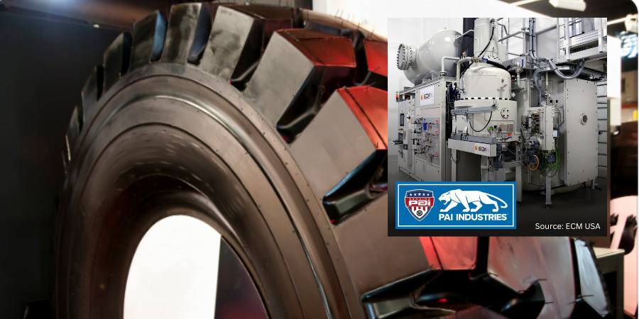
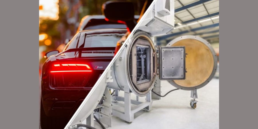
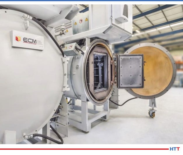
PAI Industries, a manufacturer of parts to the heavy-duty truck industry, has expanded its in-house heat treatment with a NANO vacuum furnace system.
The Georgia-based company partnered with vacuum furnace manufacturer ECM USA to transition its production line from out-sourced heat treatment to in-house vacuum technology in order to perform low pressure carburizing and through hardening around the clock.
The upgraded system will increase capacity and expedite production at PAI’s 112,000 square foot manufacturing facility. The NANO furnace system is comprised of one module with three stacked up heating cells (which can be extended to six heating cells, corresponding to two heating modules) and gas quenching cells to quench the parts. The carburizing cells are stacked up to reduce the footprint’s installation as much as possible. The furnace system integrates directly into the production line which allows it to reduce the cycle time while simplifying the flow between the machining and heat treatment.
The press release is available in its original form here.
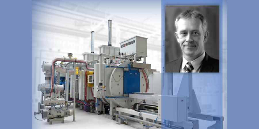
Modern industry trends and expectations pose new challenges to heat treating equipment; in addition to the expected requirements (e.g., safety, quality, economy, reliability, and efficiency), factors like availability, flexibility, energy efficiency, environmental, and the surrounding carbon neutrality are becoming increasingly important.
Maciej Korecki, vice president of Business Development and R&D at SECO/WARWICK, presents this special Technical Wednesday case study for the last day of FNA 2022 to focus on an equipment solution that meets these modern industry demands: a semi-continuous vacuum furnace for low-pressure carburizing (LPC) and high-pressure gas quenching (HPGQ).
Maciej Korecki Vice President of Business of the Vacuum Furnace Segment SECO/WARWICK
Introduction
At least 60 years ago, vacuum furnaces first appeared in the most demanding industries (i.e., space and aerospace), then spread to other industrial branches, and are now widely implemented in both mass production and service plants. Use of vacuum technology does not look like it is slowing down anytime soon.
Contact us with your Reader Feedback!
The driving forces behind this growth in vacuum technology are two-fold: first, the increasing heat treatment requirements that result from the directions of industrial development and production systems, and second, environmental protection, where the advantages of vacuum technologies are undeniable.
Traditional Atmospheric Technology
Case hardening by carburizing is one of the most widely used heat treatment technologies. It consists in carburizing (introducing carbon to the surface) followed by quenching of the carburized layer. Typically, the work is carburized in a mixture of flammable gases (CO, H2), and quenched in oil in an atmosphere furnace, using methods developed in the 1960s.
These methods have a history of development, though the question remains if the technological developments can keep up with the requirements of modern industry. Safety is an issue with this method due to the use of flammable (and poisonous) gases and flammable oil, as well as open flame, which in the absence of complete separation from the air can lead to fire, or poisoning.
In addition, they affect their environment by releasing significant amounts of heat, polluting the surroundings with quenching oil and its vapors. They require the use of washers and cleaning chemicals, emit annually tens or even hundreds of tons of CO2 (greenhouse gas, the main culprit of global warming and dynamic climate change) coming from the carburizing atmosphere, and for these reasons, they need to be installed in dedicated so-called “dirty halls” separated from other production departments.
The resulting requirement to limit the temperature of the processes to 1688-1706 oF (920-930oC) is also not without importance, as it blocks the possibility of accelerating carburization and increasing production efficiency (due to the use of metal alloys in the construction, the service life of which drops dramatically at higher temperatures) and the formation of unfavorable intergranular oxidation (IGO), which is a characteristic feature of the atmospheric carburizing method.
Quenching in oil is effective, but it does not have precise controllable, repeatable, and ecological features that heat treaters may need. Due to the multiphase nature of oil quenching (steam, bubble, and convection phase) and the associated extremely different cooling rates, it is characterized by large and unpredictable deformations within a single part and the entire load. Furthermore, there is no practical method to influence and control the quench process.
Modern Vacuum Technology with LPC and HPGQ
Vacuum carburizing appeared as early as the 1970s, but it could not break through for a long time due to the inability to control and predict the results of the process, and heavy contamination of the furnaces with reaction products.
The breakthrough came in the 1990s, when acetylene began to be used as a carbon-bearing gas and computers were employed to control and simulate the process. Since the beginning of the 21st century, there has been a rapid development of the low pressure carburizing (LPC) technology and an increase in its industrial demand, which continues today with an upturn.
Vacuum carburizing occurs with the aid of hydrocarbons (usually acetylene), which catalytically decompose at the surface, providing carbon that diffuses into the material. The process is carried out under negative pressure (hundreds of times less than atmospheric pressure) and is very precise, efficient, and uniform due to the very high velocity and penetration capacity of the gas molecules, allowing the carburizing of large and densely packed loads and hard-to-reach surfaces such as holes.
In addition, the use of non-oxygen-containing hydrocarbon atoms eliminates the qualitative problem of intergranular oxidation (IGO). The process is completely safe, there is no flammable or poisonous atmosphere in the furnace and no open flame, and the furnace can work unattended and is fully available and flexible, i.e., it can be turned on and off on demand, which does not require any preparation. Similarly, changing the carburizing parameters takes place efficiently.
Due to the design of the vacuum furnace and the use of materials with high resistance to temperature, i.e., graphite — the only limitation for the temperature of the carburizing process is the steel from which the parts are made — it is possible to carburize at higher temperatures than traditional methods allow. The result is a significantly shorter carburizing time and increased furnace efficiency versus what can be achieved in an atmosphere furnace.
Neutral gas cooling was included with the vacuum furnaces. Initially, engineers used a cooling gas (nitrogen or argon) at near ambient pressure and natural convection. Subsequent solutions introduced fan-forced gas flow in a closed circuit. The cooling efficiency under such conditions was hundreds of times lower compared to that of oil, allowing only high-alloy steels and parts with very limited cross-sections to be hardened. Over the following decades, the development of HPGQ was focused on improving cooling efficiency by increasing pressure and velocity and using different types of gas and their mixtures. Current systems have cooling efficiencies on a par with oil-based systems and enable the same types of steel and parts to be hardened, with the advantage that deformation can be greatly reduced and reproducible, and the process is completely controllable (through pressure and gas velocity) allowing any cooling curve to be executed.
Vacuum technologies have an ecological edge. Because of their design and processes, vacuum furnaces do not interfere with the immediate surroundings and are environmentally friendly, so they can be installed in clean halls, directly in the production chain (in-line). They emit negligible amounts of heat and post-process gases which are not poisonous and contain no CO 2 at all. Gas quenching eliminates harmful quenching oil and the associated risk of fire and contamination of the immediate environment, as well as the need for equipment and chemicals for its removal and neutralization. Nitrogen used for cooling is obtained from the air and returned to it in a clean state, creating an ideal environmentally friendly solution.
The presented advantages of vacuum technologies influence its dynamic development and increase the demand of modern industry, and the gradual replacement of atmospheric technologies.
Vacuum furnaces are available in virtually any configuration: horizontal, vertical, single, double, or multi-chambered, tailored to the process and production requirements. In light of recent global changes, requirements, and industrial trends, special attention should be paid to disposable, flexible, and rapidly variable production and process systems, as well as independent and autonomous systems, which include a three-chamber vacuum furnace for semi- continuous heat treatment, equipped with LPC and HPGQ.
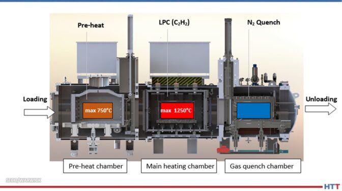
Three-Chamber Vacuum Furnace — CaseMaster Evolution Type CMe-T6810-25
This is a compact, versatile, and flexible system designed for vacuum heat treatment processes for in-house and commercial plants, dedicated to fast-changing and demanding conditions in large-scale and individual production (Fig. 1). It enables the implementation of case hardening by LPC and HPGQ processes and quenching of typical types of oil and gas hardened steels and allows for annealing and brazing. It is characterized by the following data:
working space 610x750x1000 mm (WxHxL)
load capacity 1000 kg gross
temperature 2282oF (1250oC)
vacuum range 10-2 mbar
cooling pressure 25 bar abs
LPC acetylene gas
Installation area 8x7m
Fig. 1a. Furnace CMe-T6810-25.
Fig. 1b. Fig. 1. Furnace CMe-T6810-25. On the right – view from the loading side (pre-heating chamber), on the left – view from the unloading side (quenching chamber).
The furnace is built with three thermally and pressure-separated chambers (Fig. 2.), and operates in a pass-through mode, loaded on one side and unloaded on the other, simultaneously processing three loads, hence its high efficiency. The load is put into the pre-heating chamber, where it is pre-heated to the temperature of 1382oF (750oC), depending on the requirements: in air (pre-oxidation), nitrogen or vacuum atmosphere. It is then transferred to the main heating chamber, where it reaches process temperature and where the process is carried out (e.g., LPC).
In the next step, the charge is transported to the quenching chamber, where it is quenched in nitrogen under high pressure. All operations are automatic and synchronized without the need for operator intervention or supervision.
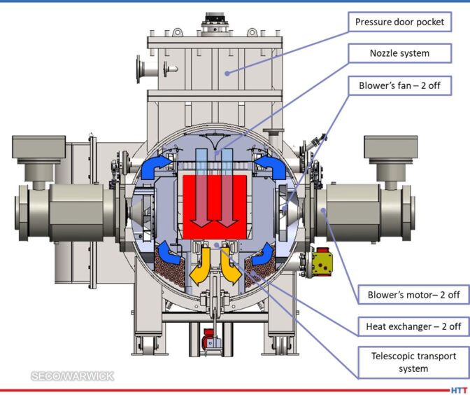
Fig. 2. Construction and schematic furnace cross-section CMe-T6810-25. Source: SECO/WARWICK
Particularly noteworthy is the gas cooling chamber, which in nitrogen (rather than helium) achieves cooling efficiencies comparable to oil (heat transfer coefficient >> 1000 W/m2K), thanks to the use of 25 bar abs pressure and hurricane gas velocities in a highly efficient closed loop system. The cooling system is based on two side-mounted fans with a capacity of 220 kW each, forcing with nozzles an intensive cooling nitrogen flow from above onto the load, then through the heat exchanger (gas-water), where the nitrogen is cooled and further sucked in by the fan (Fig. 3). The cooling process is controllable, repeatable, and programmable by gas pressure, fan speed and time. An intense and even cooling is achieved. The result is the achievement of appropriate mechanical properties of parts with minimal hardening deformations, without the use of environmentally unfriendly oil or very expensive helium.
Fig. 3. Cross-section of the furnace CMe-T6810-25 cooling chamber. Source: SECO/WARWICK
An integral part of the furnace system is the SimVaC carburizing process simulator, which enables the design of furnace recipes without conducting proof tests.
Distinctive Features of the CMe-T6810-25 Furnace
The advantages of this type of furnace — versus more traditional or past forms — can be demonstrated in a number of usability and functional aspects, the most important of which are the following:
Safety:
Safe, no flammable and poisonous atmosphere
No open fire
Production and installation:
Intended for high volume production (two to three times higher output when compared to single- and double-chamber furnaces)
Effective and efficient LPC (even five times faster than traditional carburizing)
Total process automation & integration
Clean room installation
Operator-free
Compact footprint
Quality:
High precision and repeatability of results
Uniform carburizing of densely pack loads and difficult shapes (holes)
No decarburization or oxidation
Elimination of IGO
Ideal protection and cleanliness of part surfaces
Accurate and precise LPC process simulator (SimVaC)
Quenching:
Powerful nitrogen quenching (neither oil nor helium is needed)
Reduction of distortion
Elimination of quenching oil and contamination
Elimination of washing and cleaning chemicals
Operational:
Flexible, on-demand operation
No conditioning time
No human involvement and impact
High lifespan of hot zone components — i.e., graphite
No moving components in the process chamber
Ecology:
Safe and environmentally friendly processes and equipment
No emission of harmful gases (CO, NOx, SOx)
No emission of climate-warming gas CO2
Based on the CMe-T6810-25 furnace performance, it is rational and reasonable to build heat treatment systems for high-efficiency and developmental production in a distributed system by multiplying and integrating further autonomous and independent units. The reasons for doing so are because the furnace design affords:
No risk of production total breakdown
Unlimited operational flexibility
Less initial investment cost
Unlimited multiplication
No downtime while expansion
Independent quenching chamber
Independent transportation
Independent control system
The characteristics, capabilities and functionalities of the CMe-T6810-25 furnace fit very well with the current and developmental expectations of modern industry and ecological requirements, which is confirmed by specific implementation cases.
Case Study
The three-chamber CaseMaster Evolution CMe-T6810-25 vacuum furnace was installed and implemented for production at the commercial heat treatment plant at the Polish branch of the renowned Aalberts surface technologies Group in 2020.
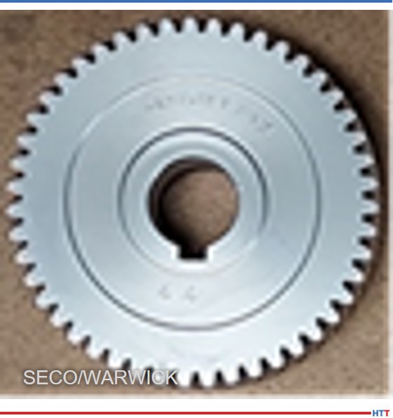
Fig. 4. Gearwheel used in the case hardening process. Source: SECO/WARWICK
The CMe furnace, together with the washer and tempering furnace, forms the core of the department's production, which is why the furnace is operated continuously. Last year, the furnace performed over 2000 processes and showed very high quality (100%) and reliability (> 99%) indicators. The very high efficiency of the furnace was also confirmed, which, with relatively low production costs, contributes to a very good economic result.
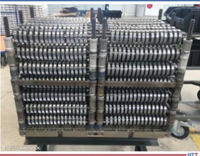
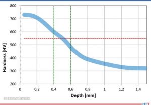
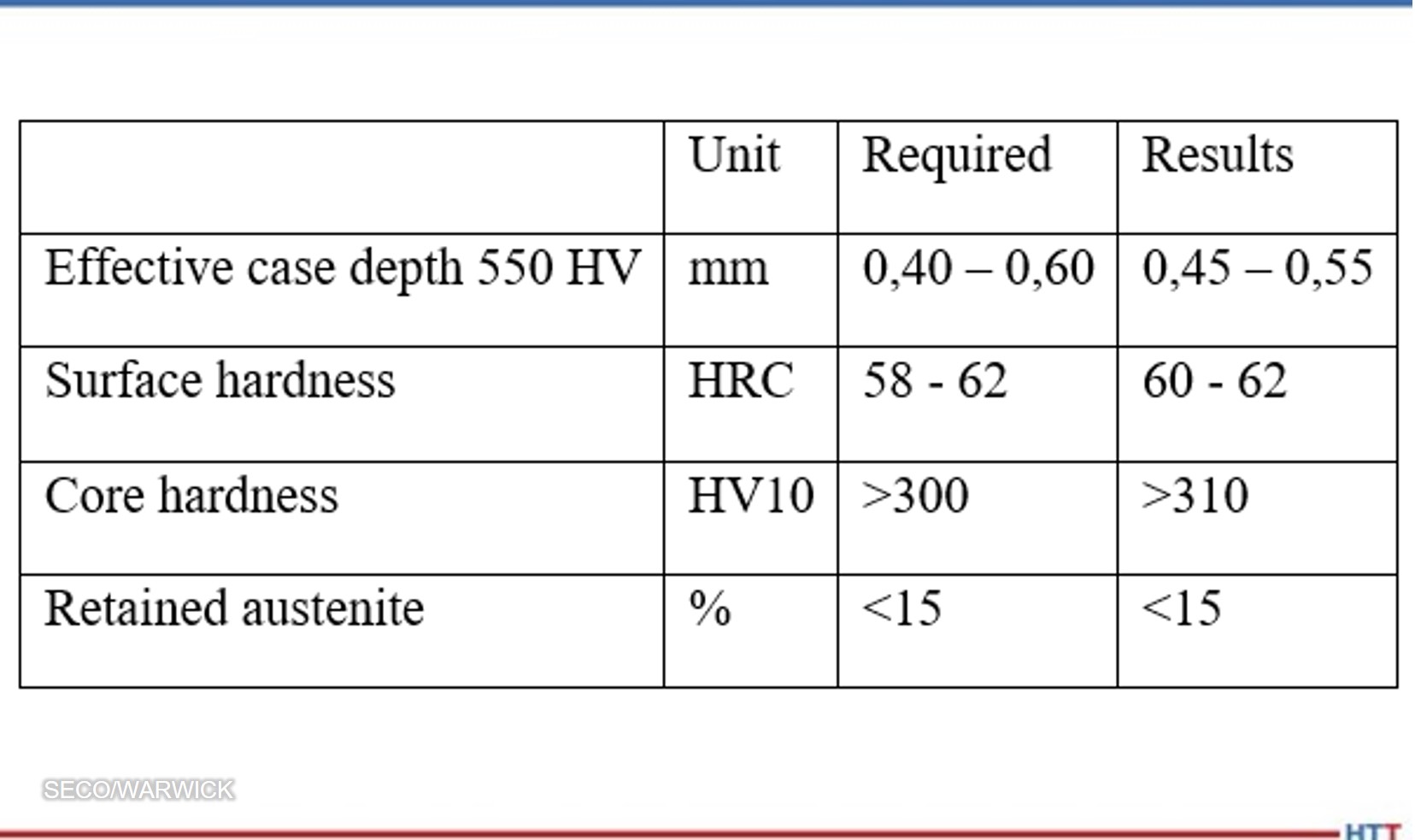
The case hardening process on gearwheels used in industrial gearboxes was taken as an example. The wheel had an outer diameter of about 80 mm and a mass of 0.52 kg (Fig. 4), and the load consisted of 1344 pieces densely packed in the working space (Fig. 5) with a total net weight of 700 kg (920 kg gross) and 25 m2 surface to be carburized. The aim of the process was to obtain an effective layer thickness from 0.4 – 0.6 mm with the criterion of 550 HV, surface hardness from 58 – 62 HRC (Rockwell Hardness C), core hardness at the gear tooth base above 300 HV10 and the correct structure with retained austenite below 15%.
Fig. 5. A photograph of the arrangement of gearwheels in the load. Source: SECO/WARWICK
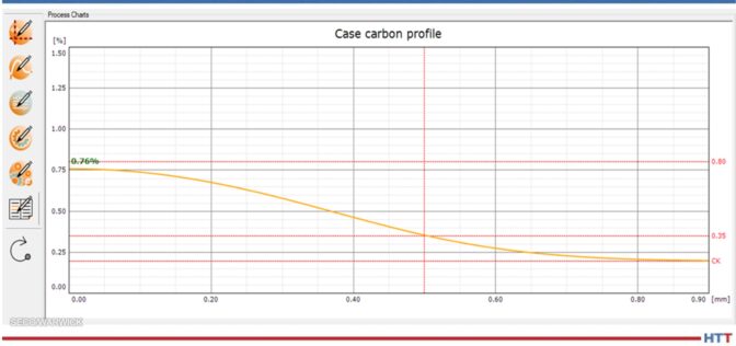
The LPC process was designed using the SimVaC® simulator at a temperature of 1724oF (940oC) and a time of 45 min, with 3 stages of introducing carburizing gas (acetylene), obtaining the appropriate profile of carbon concentration in the carburized layer, with a content of 0.76% C on the surface (Fig. 6).
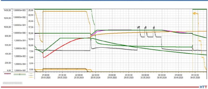
The process was carried out in the CMe-T6810-25 furnace and had the following course from the perspective of a single load (Fig. 7):
Loading into a pre-heating chamber, heating and temperature equalization in 1382oF (750oC) (100 min in total).
Reloading to the main heating chamber, heating and temperature equalization in 1724oF (940oC), LPC, lowering and equalizing the temperature before quenching in 1580oF (860oC), reloading to the cooling chamber (total 180 min).
Gradual quenching at a pressure of 24, then 12 and 5 bar, discharge of the load from a quenching chamber (total of 25 min).
Fig. 6. Carbon profile simulated by SimVaC®. Source: SECO/WARWICK
Fig. 7. Process flow in CMe® furnace parameter trends. Source: SECO/WARWICK
The load stayed the longest in the main heating chamber – for 180 minutes. This means that with the continuous operation of the furnace in this process, the cycle will be just 180 minutes, i.e., once every three hours the raw load will be loaded, and the processed load will be removed from the furnace.
In the next step, the parts underwent tempering at a temperature of 160oC.
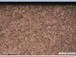
The result of the process was tested on ten parts taken from the reference corners and from the inside of the load. The correct layer structure (Fig. 8) and hardness profile (Fig. 9) were achieved, and all the requirements of the technical specification were met (Tab. 1).
Fig. 9. Hardness profile band obtained from tested gearwheels. Source: SECO/WARWICK
Tab. 1. Comparison of the parameters required and obtained in the process. Source: SECO/WARWICK
During the process, the consumption of the costliest energy factors was monitored and calculated, and the results per one load are as follows:
Electricity – 550 kWh
Liquid nitrogen – 160 kg
Acetylene – 1.5 kg
CO2 emissions – 0 kg
Cooling water and compressed air consumption have not been included as they have a negligible impact on process costs.
Summary: Efficiency and Economy
As a result of the process, all technological requirements have been met, obtaining the following indicators of efficiency and consumption of energy factors calculated for the entire load and per unit net weight of the load (700 kg):
On this basis, it is possible to estimate the total cost of energy factors in the amount of approximately EUR 100 per load or approximately EUR 0.14/kg of net load (assuming European unit costs of 2021). It is important that these costs are not burdened by CO2 emission penalties, as can happen with more traditional furnaces.
To sum up the economic aspect, based on an example process, a CMe furnace capacity of 1,500 net tons of parts per year was achieved for 6500 hours of annual furnace operation, at a cost of energy factors of about 100 EUR per load, or 0.14 EUR per kg of parts. The economic calculation is very attractive, and the return on investment (ROI) is estimated at just a few years.
Conclusion
While the advantages of this type of vacuum application are clear from this case study, the example discussed here does not represent the full capabilities of the CMe-T6810-25 furnace, even this process can be optimized and shortened, thereby increasing the furnace's efficiency, and reducing costs. It is possible to carry out carburizing processes (LPC) or hardening alone in a 1.5 h cycle, which would double the capacity of the furnace and similarly reduce the cost of energy factors and shorten the ROI time.
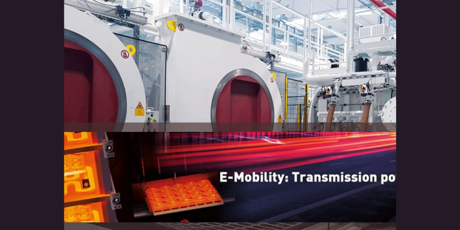
GKN Driveline Bruneck AG (GKN) is modernizing its hardening shop with two low pressure carburizing plants, gearing up for the future as a key location for the development and production of E-powertrains in the GKN group.
For the last three years, the GKN group has been concentrating the development and European production of E-powertrains at the Bruneck site in South Tyrol, Italy. Through an extensive investment program, the site was equipped with modern production technology, placing it at the core of GKN’s E-mobility strategy. Dating back to the 1960’s, the hardening shop consists of several conventional pusher furnace systems and will now be modernized with ALD Vacuum Technologies GmbH's vacuum furnaces.
"This state-of-the-art heat treatment technology puts GKN in a position to meet the unique challenges of E-powertrain production," states Matthias John, sales engineer at ALD.
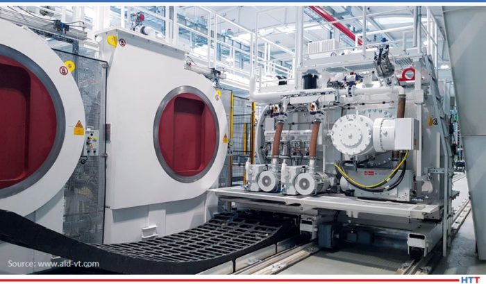
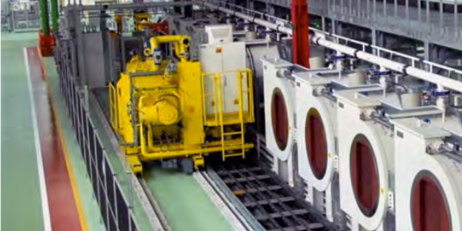
ModulTherm plant installed at GKN
In comparison with conventional combustion engine transmissions, the transmissions installed in modern electric cars are exposed to significantly higher speeds and torques. Therefore, the mechanical and metallurgical properties, as well as the dimensional accuracy of the highly stressed parts have to meet particularly high requirements. In the future, GKN intends to meet this challenge with a multi-chamber plant-type ModulTherm, and for special applications, a SyncroTherm plant. Both plants were started up in the second half of 2020.
"ALD convinced us with both, the very good results regarding metallurgical properties and low distortion of the parts. Their excellent and competent consulting reinforced us in our decision in favor of the state-of-the-art technology," explains Gianni Del Favero, value stream manager Machining and Heat Treatment at GKN. "The process combination of low-pressure carburizing (LPC) and subsequent high-pressure gas quenching (HPGQ) allows GKN to optimally adjust the parts’ properties – flexibly and component-specifically," adds John.
During the first expansion phase, in addition to the ModulTherm plant consisting of a mobile quenching module and five treatment chambers, ALD delivered fully integrated peripheral tempering and preheating furnaces, a cleaning plant, a batch buffer, and an external charge transport system.
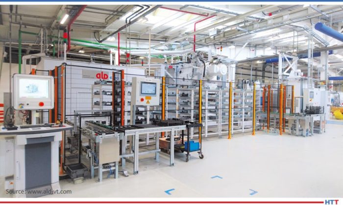
SyncroTherm plant installed at GKN
The plant can be expanded up to 10 treatment chambers, depending on demand over the following years. Consequently, GKN will be able to gradually replace the aging protective gas furnaces.
The SnycroTherm plant will mainly be used for parts which are especially susceptible to distortion. The small batch size allows for a more targeted and finely tuned quench, resulting in little change in the dimensions of the parts.
Additionally, heat treatment of small batches enables a more flexible and faster throughput of smaller load sizes throughout the overall production.
An automotive supplier and a hydraulic pump manufacturer will acquire multi-chamber vacuum furnace system for low pressure carburizing.
For the automotive supplier of innovative driveline solutions, the system is estimated to reduce CO2 emissions significantly for vacuum carburizing versus an existing atmosphere carburizing furnace. For the hydraulic pump manufacturer, the modular flexibility of this specific furnace was the most important advantage.
ECM Flex Multi-Chamber System Source: ECM USA, Inc.
The supplier, ECM USA, Inc., notes that their Flex Multi-Chamber System is built as a standard system with the possibility to further expand its capacity and/or to upgrade to a high level of automation (robots, AGVs, vision systems, or other 4.0 elements). In addition to modularity, several processes can be handled in the Flex furnace, such as: low pressure carburizing (LPC), vacuum tempering and a combination of vacuum sintering followed by hardening.
This stems from advanced automation technology -- including robotics -- acting as driving forces behind increased use of more eco-friendly applications outside the LPC-HPGQ sector. This includes, but is not limited to, multiple tool steel processing systems, brazing applications, and rapid thermal processing (RTP) systems.
Piotr Zawistowski Managing Director SECO/VACUUM TECHNOLOGIES, USA
Source: secowarwick.com
A new vacuum furnace for a division of the US Department of Defense will bolster its capability to ensure supply chain reliability. The furnace is equipped to handle steel hardening, surface engineering, vacuum annealing, nickel alloy processing, and titanium heat treatment.
As a critical supplier of aerospace components to the US Department of Defense, this division will use the new vacuum oil quenching furnace, provided by SECO/WARWICK, Group, to handle functions of the department’s existing heat treatment furnaces and expand their capabilities. The addition of low pressure carburizing (LPC) and high pressure gas quenching (HPGQ) is new to this location.
“Assuring redundancy in heating needs of this location was critical,” said Piotr Zawistowski, Managing Director of SECO/VACUUM.
Jason Orosz, President of Nitrex Heat Treating Services
A new plant investment aimed at expanding the Aurora, Illinois commercial heat treat facility located just west of Chicago was announced. The production expansion will add a fourth building on the property to house a new low-pressure carburizing (LPC) system and secondary heat-treating equipment.
President of Nitrex Heat Treating Services, Jason Orosz made this announcement earlier in the month. The new ECM vacuum carburizing furnace with oil quench capabilities will help meet growing demand from makers of high-end critical parts within the automotive, aerospace, and tooling industries. The 20-bar dual-chamber furnace has a workload size of 40” L x 24” W x 28” H (1000 x 600 x 715 mm) and a load capacity of 1500 lbs. (680 kg).
Nitrexbroke ground for the new building on July 20th, and will connect to an existing structure, Building 3. According to Bill Walter, facility manager of Nitrex Aurora, the construction project will be completed in January 2021, and production on the LPC furnace is expected to begin in April 2021.
From left to right : Groundbreaking with Tom Cooper (Vice President of Business Development), Bill Walter (Facility Manager), and Raja Gumber (Senior Account Manager)
The expansion will increase the production footprint by 11,000 square feet to support current demand as well as future growth. Once this building is completed, the total floor space will be over 50,000 square feet.
Listen here to Jean-François Cloutier, Nitrex CEO, as he explained even more of Nitrex's commitment to end-users and global growth.
A systematical approach regarding different distortion potentials in the process chain describes the influence on dimensional and shape changes of gears and sliding sleeves after case-hardening, like part geometry, cold and hot forming of blanks, carburizing concept and temperature profile, oil and gas quenching, as well as individual press and batch hardening. The results show an excellent potential of the new SyncroTherm® concept compared to the conventional case-hardening process for gears and sliding sleeves. Stable distortion characteristics even at elevated temperatures and without decreasing to hardening temperature as well as a good performance after two-dimensional batch quenching instead of the much more expensive individual press quenching were found in this study. Very sensitive part geometries are still a challenge. A clear limitation was found when processing cold formed blanks without annealing before soft machining.
Dr. Volker Heuer, Gunther Schmitt, Dr. Thorsten Leist, ALD Vacuum Technologies GmbH, Hanau
1. Introduction
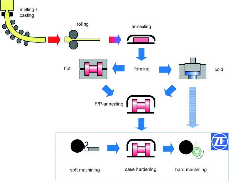
Fig. 1. Process chain for transmission parts
Case hardening is the most common heat treatment for gears, shafts and synchronizer parts used in gear boxes for automotive and commercial vehicle applications. A combination of high fatigue resistance as well as good machinability and reliable process stability in heat treatment ensures transmission components with maximum strength, excellent performance and cost efficient production. In order to decrease the costs for hard machining and reduce the risk of grinding burns the knowledge of distortioncharacteristics for the individual part as well as distortion carrier potentials of the entire process chain is essential for an improved series production with minimum stock removal [1]. Even today with much higher requirements relating to lightweight design of automotive part geometries this aspect becomes more and more important [2]. Predictable and stable distortion characteristics are still a challenge especially for sensitive parts with thin cross-sections, non-symmetric design and a global production with many different suppliers in the process chain. In a constant pursuit for optimizing, ZF in Friedrichshafen investigated the potential of new heat treatment concepts with the advantages of reduced costs, quicker processes and less distortion. A comparison of the new heat treatment concept SyncroTherm® from ALD Vacuum Technologies was performed with the conventional benchmark concepts of a) case-hardening of gears in a pusher-type furnace with atmospheric gas carburizing and oil quenching and b) press quenching of sliding sleeves directly after gas carburizing in a rotary furnace. The “SyncroTherm®” heat treatment concept combines the benefits of smaller furnaces and two-dimensional batches, fast low-pressure carburizing (LPC) at elevated temperatures and reduced distortion by applying high-pressure gas quenching and the possibility of part-related individual quenching parameters [3].
2. Standard processes for transmission components at ZF Friedrichshafen
2.1 Material, forging and machining
The material for transmission components like gears and synchronizer parts is the case-hardening steel ZF7B which is a modified 20MnCr5. The process chain is shown in Figure 1. The material for automotive and commercial vehicle applications is usually continuously casted and formed to different bar geometries in the steel mill. The forging supplier performs either hot or cold forming of blanks. The gears investigated in this study were all hot formed and later F/P-annealed with an isothermal transformation in order to ensure a good machinability of the ferritic/ pearlitic microstructure. The forged blanks are soft machined by turning and teeth milling. Measurements of characteristic dimensions, shapes and teeth geometries were performed before and after heat treatment in order to describe the distortion behavior. Grinding the bore and teeth flanks is usually performed as the last process before assembling into the gear box. Two different process chains were investigated for the siding sleeve. The first one was similar to the gears with hot forming, F/P-annealing and soft machining. The other process chain for similar part geometry of the sliding sleeve was cold rolling and broaching of the internal spline without F/P-annealing. Different dimensions and shapes which are sensitive to distortion were measured before and after case hardening.
2.2 Case-hardening in pusher-type furnaces
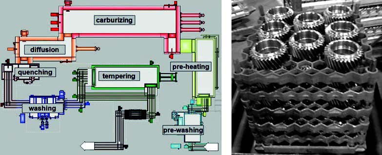
The typical final heat treatment of gears is case-hardening in a pusher-type furnace. The gears are charged in three-dimensional batches of around 220 kg per batch including fixtures. The batches of helical and planet gears which were investigated in this study were loaded by different layers of gears on grids (Figure 2). Depending on the case-hardening depth with an individual cycle time the batch is pushed through the furnace with the different linked processes pre-washing, pre-heating at 480 °C, carburizing at 940 °C, decreasing to hardening temperature 850 °C, oil quenching, washing, tempering at 170 °C and cooling down to approximately 50 °C.
Fig. 2. Schematic depiction of pusher furnace (l.) and 3D batch of helical gears (r.)
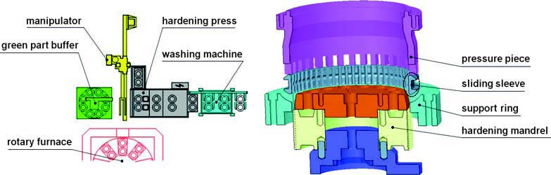
Fig. 3. Schematic depiction of press hardening cell (l.) and press hardening tools (r.)
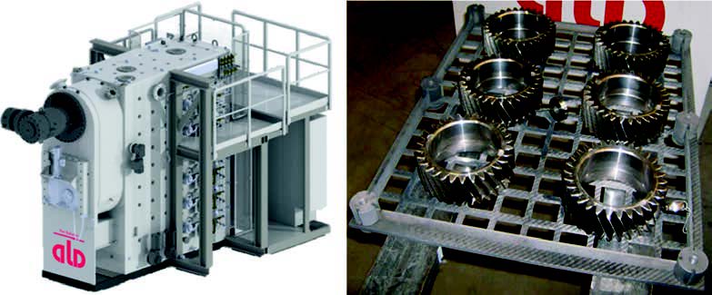
Fig. 4. ALD SyncroTherm® furnace (l.) and 2D batch of helical gears (r.)
2.2 Case-hardening in rotary furnaces and press quenching
More distortion critical synchronizer parts, like the sliding sleeve, are carburized in a rotary furnace at 930 °C with different levels in the furnace.For a three-track press quench three parts are laying on a tablet and the tablet moves in a cycle time of approximately 70 s through the rotary furnace in order to achieve the required case-hardening depth of around 0.5 mm. The parts are quenched directly from carburizing temperature 930 °C and different tools are fixed to the part before quenching which is shown in Figure 3. During the quenching process the inner diameter of the sliding sleeve shrinks onto the mandrel with similar tooth geometry as the internal spline of the part. This behavior enables a constant inner diameter and position of teeth with less run-out and scattering. In order to adjust the flatness the sliding sleeve is pushed by a pressure piece onto the support ring during quenching. All tools are designed with oil drillings in order to achieve an efficient and uniform quenching of the cross-section. The distortion characteristics of press quenched parts are extremely depending on the design of individual tools and the quenching parameters like temperature and flow of the quenching oil or retention force of the pressure piece. Most synchronizer parts are ready for assembling after press hardening and shot blasting, no additional hard machining is performed anymore.
3. Investigation
The main idea of ALD-SyncroTherm® concept is a small and flexible furnace that can realize a quick low-pressure carburizing process (LPC) at elevated temperatures and reduced distortion behavior of the carburized parts by using an adjustable high-pressure gas quenching. Differently from the standard processes at ZF, parts are loaded in one single 2D-layer on light carbon-fibre tablets, as shown in Figure 4, and then directly heated up to carburizing temperature real quick, which can be up to 1050 °C. The LPC furnace with its small floor space of e. g. a turning machine has up to six single carburizing slots, where each tablet can be heat treated individually. After the carburizing process has been finished, the parts are transported to the internal gas quenching chamber where the parts are quenched directly from carburizing temperature (see Figure 4 left) [4].
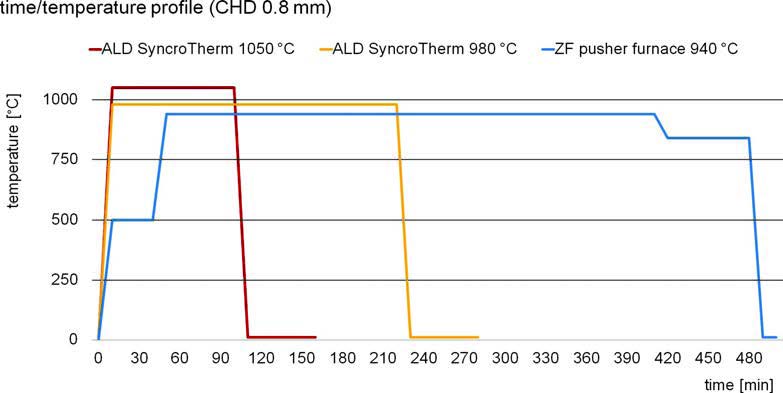
Fig. 5. Time/temperature profile for helical gears with CHD 0.8 mm
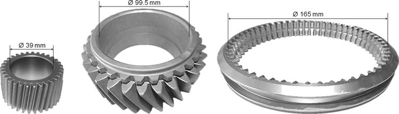
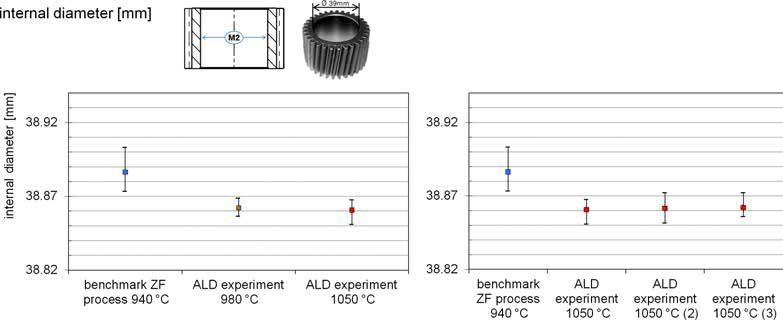
This is also a deviation to the direct batch quenching process at ZF where the part temperature is lowered to hardening temperature 840 °C before quenching with respect to distortion. Figure 5 shows a comparison of three different time/ temperature profiles which were tested within this analysis in order to achieve a CHD of 0.8 mm. The standard batch hardening process in a pusher-type furnace is compared to two different LPC processes with variation in carburizing temperature. In order to reduce distortion already during heating, the parts in the standard process at ZF are not being heated up to carburizing temperature directly but have a pre-heating step at 490 °C in order to equalize the core and surface temperature. For the LPC process with carburizing at 980 °C the overall process time is much shorter due to the higher temperature and the missing pre-heating step and the direct quenching from carburizing temperature. The reduced process time is even more pronounced when carburizing is performed at 1050 °C. All three profiles have been tested with different common parts for truck and bus transmissions. Figure 6 shows the three types of parts that have been chosen. The tests have been performed with a small planetary gear for bus transmissions and a heavier and bigger helical gear for heavy truck transmissions. Both gears are direct hardened at ZF by using the batch hardening process in a pusher-type furnace. Other experiments have been performed with two different types of sliding sleeves but similar geometry, as shown in Figure 6. Both types of sliding sleeves were processed differently: one type is machined from cold formed blanks whereas the other type is machined from hot formed and F/P-annealed blanks. Due to their high distortion potential, the standard process for sliding sleeves at ZF is carburizing in rotary furnaces with a consecutive press quenching. For each part many different dimensions, shapes and tooth geometries were measured before and after heat treatment in order to describe the individual distortion characteristics. Here, just critical features are shown which are representative for the distortion characteristics. For gears those are the internal diameter of the bore and the angular flank deviation fHb of the teeth. For the sliding sleeves the diameter of the internal spline and the flatness of the end face are the critical characteristics.
4. Results
4.1 Metallographic results
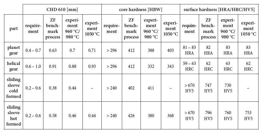
Metallographic results of the different tests were analyzed by investigation of one part from each batch since a correct metallographic result is the premise for the later analysis of the distortion and evaluation of the LPC process. Table 1 shows the different metallographic results of the analyzed parts from experiments at different carburizing temperatures and the results of the ZF benchmark processes, as a comparison. It shows that the LPC furnace is able to produce correct and repeatable metallographic results within specification regarding CHD, surface hardness and core strength.
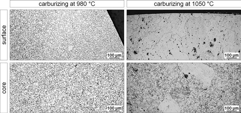
Fig. 7. Grain sizes of planet gear after carburizing at 980 °C and 1050 °C
For bigger cross sections, like for the helical gear, the lower core strength is explainable due to the lower quenching speedof gas quenching compared to oil quenching in general and even further reduced gas quenching speed with respect to distortion of this gear. Additionally the amount of retained austenite could be maintained well within the required specification (max. 30 %) with the ALD furnace, even after quenching directly from carburizing temperature. Figure 7 shows micrographs of the grain sizes from core and surface samples taken from the heat treated parts with carburizing at 980 °C and 1050 °C and etched according to Bechet-Beaujard. Whereas the samples which were carburized at 980 °C show a homogeneous distribution of fine grains with grain size classes 5 and finer, the samples carburized at 1050 °C show an inhomogeneous distribution and very coarse grains with grain size classes up to 1 and coarser. These findings where confirmed through all performed experiments. This shows that conventional ZF case-hardening steel grades can already provide grain size stability up to 980 °C but not higher. For carburizing the parts at 1050 °C significant grain growth will occur in conventional grades. In order to prevent coarse grains microalloyed case-hardening steels are definitely necessary in order to meet the grain size specification [5]. Even knowing this fact already at the beginning, distortion experiments were performed at the higher temperatures, nevertheless, in order to analyze also the effect of grain growth on the part geometry and on distortion characteristics after heat treatment.
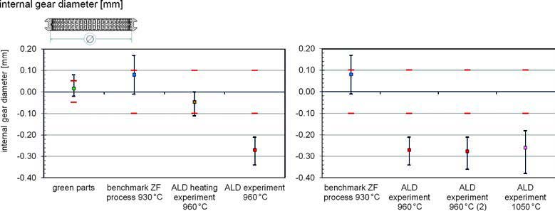
4.2 Comparison of distortion results – internal diameter of planet gears
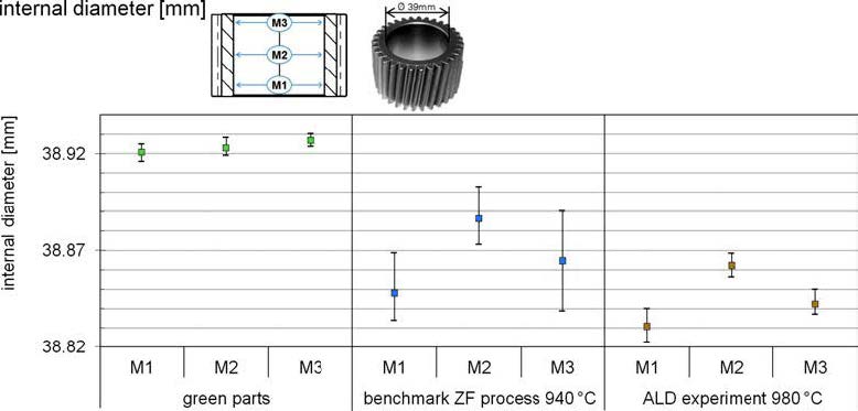
In order to analyze the distortion of the internal bore, it was measured in three different levels of the bore. Figure 8 shows the location of the measuring levels M1-M3 within the internal bore of planet gears and the respective results from the green parts (12sample parts), the benchmark process (24 sample parts) and the LPC experiment at 980 °C (12 sample parts).
Table 1. Metallographic results
Fig. 8. Barrel shape of the internal diameter of the planet gear after direct hardening
Fig. 9. Comparability (l.) and Stability (r.) of the internal diameter at higher carburizing temperatures
Whereas the three average values of the green parts show a perfect cylindrical form of the bore with almost no scattering, the measurement of the ZF benchmark process carburized at 940 °C shows a clear barrel shape of the internal bore with higher scattering. The same shape change can be observed in the results from the LPC experiment, although the value of the shape change and the scattering is less pronounced. The significantly lesser scattering of the heat treatment distortion compared to the benchmark process was even realized during experiments with a high carburizing temperature of 1050 °C (see Figure 9 left). Moreover the average value stays on the same level as after the experiment at 980 °C even if a significant grain growth was determined with no negative influence on distortion characteristics. The smaller diameter of the bore compared to the ZF process is explainable with the direct quenching from carburizing temperature without lowering the temperature, as it is done during the ZF process. These results are very stable even after carburizing at 1050 °C and were confirmed by two additional batches with same heat treatment parameters (Figure 9 right).
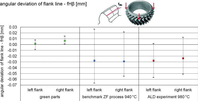
4.3 Comparison of distortion results – angular deviation of flank line fHβ
The value fHβ describes the angular deviation of a measured line along the tooth flank (see Figure 10) from the theoretically defined line of the tooth flank. It was measured on the left and on the right flank of three teeth per gear with a distance of 120° on the circumference. The same teeth and flanks have been measured before and after heat treatment. The results show that the fHβ of both flanks is highly influenced by the case hardening process. If compared to the measurements of the green parts, where the average value of the deviation is almost 0 mm with a maximum range of 0.02 mm, the average deviation after the benchmark heat treatment is −0.03 mm with a wide range for both flanks up to 0.08 mm.
Fig. 10. Comparison of flank line deviation of helical gear standard and LPC process
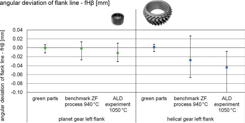
Fig. 11. Comparison of flank line deviation of planet and helical gear
The results of the LPC experiments are comparable to the benchmark process and even slightly better. While average deviation of both tooth flanks is on the same level as the value after the ZF process, the range is slightly smaller. The maximum range for the LPC tests at 980 °C is 0.06 mm even if the parts were directly quenched from carburizing temperature. Figure 11 shows that the average angular deviation and the range are less influenced by the heat treatment concept and the carburizing temperature of the process. Especially for the LPC process, negative influences on distortion may be compensated by adapted and optimized gas quenching parameters. Comparing the much smaller planet gear (tooth width 34 mm, helical angle 7°) with the bigger helical gear (tooth width 50 mm, helical angle 23°) different characteristics regarding the average and range of angular deviation can be determined. The planet gear shows a similar average of fHβ before and after heat treatment for both heat treatment concepts and different carburizing temperatures. The range of fHβ is slightly increased after heat treatment and is similar for the benchmark and the LPC process. For the bigger helical gear it is different. The average of fHβ changes afterheat treatment significantly and the range is much higher. There is also a significant difference between the benchmark and the LPC process for the average of fHβ but not for the range of fHβ. This is a clear indication for more sensitive distortion characteristics of the helical gear. The significant difference in distortion behavior is mainly influenced by the bigger helical angle of the wider helical gear compared to the narrower planet gear with the smaller helical angle [6].
4.4 Comparison of distortion results – sliding sleeves
Sliding sleeves are distortion critical parts and therefore are case hardened and press quenched as a standard process in the ZF Company. In order to define the distortion of sliding sleeves, the internal diameter and the flatness where investigated. Different from the batch quenching in the LPC furnace, both characteristics are being controlled during press quenching of the ZF benchmark process by using individual press hardening tools. The investigation has been performed with 10 pieces of green parts, 25 pieces for the benchmark process and 10 pieces for each of the LPC experiments. For a better comparability of the results, the values of the measurements have been standardized and fitted into the tolerance band so that a value of 0 mm indicates the exact center of the allowed tolerance.
4.4.1 Cold formed
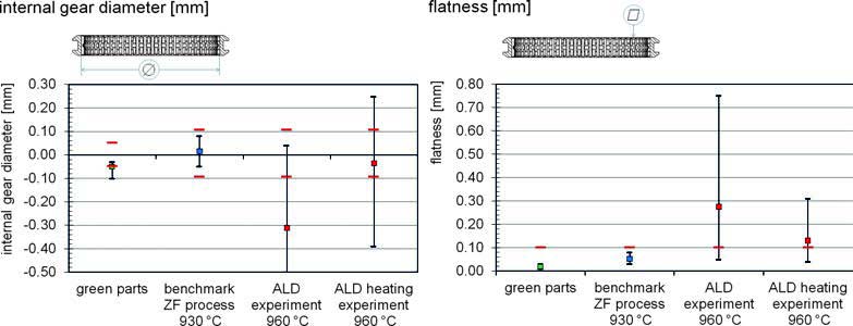
The investigation of the sliding sleeves machined from cold formed blanks shows how the press hardening tools of the ZF benchmark process influences the internal diameter by forcing it to shrink onto a defined tool diameter of the hardening mandrel. The intended negative deviation of the green parts of 0.05 mm from the ideal diameter, based on long-term experiences, is corrected after the ZF heat treatment (Figure 12). Additionally the press hardening tools reduce the scattering of dimensional and shape changes to a minimum. The results after carburizing at 960 °C and gas quenching in a batch of the LPC furnace display a tremendous heat treatment distortion and scattering of results in a large range. Even with optimized quenching parameters the range is nearly 1.0 mm. The reason for this worse distortion behavior can be explained by the high amount of residual stresses after cold forming of the blanks which are not removed by later annealing and soft machining.
Fig. 12. Distortion results of the internal diameter (l.) and flatness (r.) of cold formed sliding sleeves
Fig. 13. Distortion behavior (l.) and stability (r.) of the internal diameter of hot formed sliding sleeves
A heating experiment where the parts were heated up to 960 °C without carburizing and afterwards slowly cooled down to room temperature was performed. This test was done in order to define the amount of distortion that is induced by residual stresses from former process steps already during heating. It clearly shows a high distortion potential of the sliding sleeves machined from cold formed blanks. Whereas the average diameter does not change the scattering is very large and, with a range of 0.65 mm, almost as wide as after the complete process with carburizing and quenching (Figure 12 left). This assumption was also confirmed by the distortion analysis of the parts flatness (Figure 12 right) where similar distortion behavior can be observed. This means that, without controlling dimensions by hardening tools, sliding sleeves that are machined from cold formed blanks cannot be heat treated within the required specification.
4.4.2 Hot formed
The distortion of sliding sleeves machined from hot formed blanks with a later F/P-annealing before soft machining, which reduces the residual stresses from prior process steps to a minimum, is significantly different compared to the cold formed sliding sleeve without F/P-annealing like previously described. The average diameter of the sliding sleeve after the ZF benchmark process is located near the upper tolerance with a slightly wider scattering (Figure 13 left) than after the heat treatment of cold formed sliding sleeves. Even by using optimized hardening tools for each part geometry the individual distortion behavior depends also on the forging lot and hardenability of the individual steel heat. Although some parts were outside of tolerance the final gage test applied on these parts showed that they are still usable for assembly. The heating experiment in the LPC furnace without carburizing reveals a smaller distortion potential due to minimized residual stresses of the hot formed and F/P-annealed blanks. Looking at the range of the diameter, it is just slightly wider when compared with the range of the green parts. This minimal distortion regarding the range can be preserved even after a completed experiment with carburizing and optimized gas quenching. Still, without the limiting function of a hardening mandrel, the average diameter shrinks as much as −0.38 mm after the heat treatment (Figure 13 left). The reproducibility of the described behavior of the LPC experiment with hot formed sliding sleeves was confirmed by two additional experiments with carburizing temperatures of 960 °C and of 1050 °C (Figure 13 right). Even the sliding sleeves from the final test that were carburized at 1050 °C show an average diameter that remains stable at the same level as those carburized at 960 °C. The additional scattering, that results of a higher quenching intensity, is minimal and in total still less than the tolerance band width of 0.2 mm. Therefore, producing sliding sleeves with the LPC process that fit the requirement might be possible if the dimensions of soft machining are adjusted with respect to the distortion behavior after heat treatment. This conclusion bears the potential of reducing heat treatment costs for distortion critical parts made from hot formed and F/P-annealed blanks by replacing the cost intensive press quenching followed by washing and shot blasting with a batch quenching process in the LPC furnace. However, this potential has to be investigated more in-depth before changing the process chain.
5. Summary
This paper describes a systematical analysis of different distortion potentials for case hardening processes. Different influences on distortion characteristics were investigated and defined such as different part geometries, process chains, carburizing concepts, temperature profiles and quenching methods. The main focus was on the comparison of the new SyncroTherm® concept by ALD Vacuum Technologies GmbH with established case hardening processes at ZF Friedrichshafen AG. The results show an excellent potential of the new LPC concept for gears and sliding sleeves. Stable distortion characteristics even at elevated temperatures and without decreasing to hardening temperature as well as a good performance after two-dimensional batch quenching instead of the much more expensive individual press quenching were found. However, very sensitive part geometries, such as sliding sleeves, are still a challenge. A clear limitation regarding the SyncroTherm® concept was found for sliding sleeves machined from cold formed blanks without F/P-annealing before soft broaching the internal spline.
Zoch, H.-W.: Distortion Engineering – Interim results after one decade within the Collaborative Research Center. Proc. 3rd Int. Conf. on Distortion Engineering, 1416.09.11, Bremen, H.-W. Zoch, Th. Luebben (Eds.), 2011, p. 569‒579; Mat.-wiss. Werkstofftechn. 43 (2012) 1‒2, p. 9‒15, DOI: 10.1002/mawe.201100881
Heuer, V.; Löser, K.; Schmitt, G.; Ritter, K.: Einsatzhärten im Fertigungstakt. HTM J. Heat Treatm. Mat. 68 (2013) 3, p. 113‒123, DOI: 10.3139/105.110184
Heuer, V.; Leist, Th.; Schmitt, G.: Distortion control through synchronized vacuum heat treatment. Proc. 5th Int. Conf. on Distortion Engineering, 23-25.09.15, Bremen, H.-W. Zoch, Th. Luebben (Eds.), 2015, p. 183‒192
Hippenstiel, F.; Kohlmann, R.; Bleck, W.; Clausen, B.; Hoffmann, F.; Pouteau, P.: Innovative Einsatzstähle als maßgeschneiderte Werkstofflösung zur Hochtemperaturaufkohlung von Getriebekomponenten. HTM J. Heat Treatm. Mat. 57 (2002) 4, p. 290‒298
Heeß, K.: Maßund Formänderungen infolge Wärmebehandlung von Stählen.
ed., Expert Verlag, Renningen, 2007. – ISBN 978-3-8169-3067-9
“The energy optimization of thermoprocessing equipment is of great ecological and economical importance. Thermoprocessing equipment consumes up to 40 % of the energy used in industrial applications in Germany. Therefore it is necessary to increase the energy efficiency of thermoprocessing equipment in order to meet the EU’s targets to reduce greenhouse gas emissions. In order to exploit the potential for energy savings, it is essential to analyze and optimize processes and plants as well as operating methods of electrically heated vacuum plants used in large scale production. For processes, the accelerated heating of charges through convection and higher process temperatures in diffusion-controlled thermochemical processes are a possibility. Modular vacuum systems prove to be very energy-efficient because they adapt to the changing production requirements step-by-step. An optimized insulation structure considerably reduces thermal losses. Energy management systems installed in the plant-control optimally manage the energy used for start-up and shutdown of the plants while preventing energy peak loads. The use of new CFC-fixtures also contributes to reduce the energy demand.”