Heat TreatToday is excited to announce the addition of Heather Falcone to the editorial and podcast team, beginning on Monday, March 3, 2025. She will be taking on the responsibilities of content editor for the daily e-newsletter, original content writer, and Heat TreatRadio contributor.
Heather, the founder and principal of Falcone Consulting, LLC, is a servant leader with over 20 years of experience in heat treating, brazing, and chemical processing. She spent most of her formative years as a second-generation member of a family-owned heat treating and brazing business. As the former CEO of Thermal-Vac Technology, she successfully led the company through the pandemic, ensuring stability while propelling it into a new era that resulted in a successful exit in 2024. Passionate about challenging the status quo, she champions diverse teams and fair chance hiring, with a focus on developing successful teams that are future-proof and thriving.
Beyond her position as founder and principal at newly formed Falcone Consulting LLC, Heather is a board member, coach, speaker, and writer, advocating for small businesses, workforce development, and success for the heat treat community at large. She provides her expertise in aerospace specifications and the Nadcap process in an ongoing role as the special project consultant for Cook Induction Heating in Maywood, California. Additionally, she has played a pivotal role in industry organizations like the Metal Treating Institute, AMEC, and Nadcap, while also supporting local nonprofits such as Chrysalis and the Orange County Workforce Development Board.
“We’re thankful to have Heather joining the Heat TreatToday team,” said Doug Glenn, founder, owner, and publisher of Heat TreatToday. “I’ve known Heather for many years and have been impressed with her initiative, courage, and fearlessness in everything she does. As an organization that is deeply invested in making sure in-house heat treaters have the information they need to become more efficient and profitable, Heather will be an excellent addition to our editorial team. She knows the industry; she knows what our readers need. And as we all know, the happier the readers, the happier our advertisers.”
Heather is an Ironman triathlete, a Seven Summits enthusiast who has summitted Mt. Kilimanjaro and trekked in the Everest region, and a loving wife and mother to two teenage boys.
For more information, click here for Heather’s LinkedIn page, here for Falcone Consulting’s website, or here for her Heat TreatToday 40 Under 40 recognition in 2019.
Jim Roberts, president of U.S. Ignition, joins us in the renewal of the Combustion Corner column. In this installment, Jim establishes that the goal of the series is to provide informative content to “furnace guys” about the world of combustion, furthering the spirit of the Heat Treat Today motto: “We believe people are happier and make better decisions when they are well informed.”
This informative piece was first released in Heat Treat Today’sFebruary 2025 Air/Atmosphere Furnace Systems print edition.
Contact us with your Reader Feedback!
So … A guy walks into a room full of furnace guys …
And the story (or joke) begins again. I used to be one of the furnace guys. It’s a really niche group of strange, unique, and sometimes knowing people, who, by the way, are not gender specific. To me, “a guy” is a moniker as specific as saying that person over there is a swimmer.
But as furnace guys, those same individuals have a peek at the stuff that normal planet walkers don’t. They — or rather WE — know how to almost tame the beast. We have learned what it means to control temperatures that can crack stone. We can bend metal and make it do what we want at temperatures that the human eye cannot gaze upon without safety filters between us and the beast.
And what is this beast? It’s called combustion. It’s a phenomenon that allows the very air around us and anciently sourced resources to burn like hellfire and yet still do our bidding. But there are fewer and fewer guys who manage the beast these days. And that is how a column like this takes launch.
This publication, and its talented editorial staff, have always been driven to provide information that, in their own words, will allow the greater masses this privilege: “We believe people are happier and make better decisions when they are well informed.”
It was not lost on the staff that with dwindling numbers of longtime combustion people some of the benefits of being “well informed” were needed. They felt information could be presented in such a fashion that old-timers like me could share some of the tried-and-true techniques that we have used over the years. The hope is to not only make the workplace safer, but also to increase efficiency and performance in the processes that utilize combustion.
When we walk into almost any facility and go over to the underperforming furnaces, we can bet part of the problem will be inlet air source or exhaust outlet issues.
To some, this will seem like remedial information. That is GREAT. Because that means that you already understand a fair portion of the pathway to combustion performance. You can be the lead in your facility on combustion safety and understanding. Yay!
We are going to start with a visit to an article I wrote some time ago that then later became a pamphlet called “10 Combustion Tips.” It was written with plant maintenance guys in mind as they traveled the factories and facilities that they had responsibility for. We’ll turn this into a series of tips that are really intended for those less experienced to start. We’ll continue in upcoming editions of Heat Treat Today, and hopefully, everyone will feel like this was beneficial when cruising the aisles of your factories.
Tip 1: Keep the Process Air Filters Clean
I know, this seems so obvious, doesn’t it? Utilities tell us over and over to keep your home furnace filters clean. But I would be willing to bet that almost 30% of all furnace issues that we see in the field start at the blower supplying our combustion air. It’s the lungs for your burners! Any filter blockage will result in serious problems. As the system impedes under a clogged filter, your process may not get the required input. Clogged filters put undue strain on the combustion air blowers over time, so your electrical and motor maintenance costs may escalate. Additionally, the burners may go fuel rich. This wastes fuel and can create carbon, which at its best is an insulator. At its worst, it is a fire hazard.
Tip Solutions
A. Check the filters monthly: It is pretty easy to see if a filter is dirty. Your production folks may have even told you the furnace is slowing down. Less air, less heat. Take a peek … you will know. If it’s a fiber-based filter, replace it. Better yet, make it a habit to check filters every month.
B. Clean the screen: If not a replaceable filter, clean the metallic/plastic screen type with some solvent that will cut the machine/quench oil that’s probably the clog culprit. DO NOT put the filter back on dripping wet with solvent. I apologize to furnace guys out there for having to explain that, but it’s the new world, right? If you didn’t understand why, please refer to the movie “Back Draft.”
C. Get outside: Consider ducting an outside air source to the combustion air blower. Fresh air delivered at a stable temp will always help with furnace and burner performance.
So there, was that so hard? Nope, almost simple. And yet when we walk into almost any facility and go over to the underperforming furnaces, we can bet part of the problem will be inlet air source or exhaust outlet issues.
Don’t let it be your plant. See you next issue.
About the Author
Jim Roberts President US Ignition
Jim Roberts, president at US Ignition, began his 45-year career in the burner and heat recovery industry directed for heat treating specifically in 1979. He worked for and helped start up WB Combustion in Hales Corners, Wisconsin. In 1985 he joined Eclipse Engineering in Rockford, IL, specializing in heat treating-related combustion equipment/burners. Inducted into the American Gas Association’s Hall of Flame for service in training gas company field managers, Jim is a former president of MTI and has contributed to countless seminars on fuel reduction and combustion-related practices.
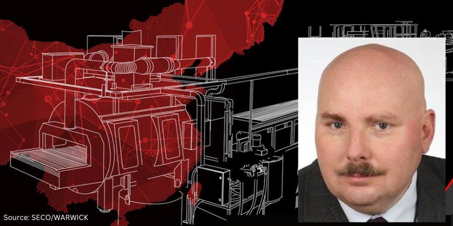
A company that supplies metal injection molded components for the aviation industry has expanded its production capabilities with a vacuum furnace. This solution will increase the capacity to provide hardening process services while meeting aviation standards required by the industry.
Sławomir Woźniak President of the Management Board SECO/WARWICK Group
The Vector® vacuum furnace will process materials using an additional argon hydrogen partial pressure system, providing heating at a high level: 2192˚F (1200˚C). This is SECO/WARWICK‘s second collaboration with the company, one of the largest manufacturers offering metal injection molding technology with manufacturing capabilities including vertical integration of finishing technologies such as nickel and trivalent chromium electroplating, vacuum heat treatment and seal hardening, as well as precision grinding and CNC machining with micron tolerances.
“This partner is a global brand which has shown their trust in us for the second time by ordering a vacuum furnace, which we will now be able to service locally and more comprehensively,” said Sławomir Woźniak, president of the management board, SECO/WARWICK Group.
The furnace’s pumping system enables vacuum processes to be carried out in medium and high ranges, thanks to the use of a very good pumping system, and incorporates three process gases: argon, nitrogen, and hydrogen.
Press release is available in its original form here.
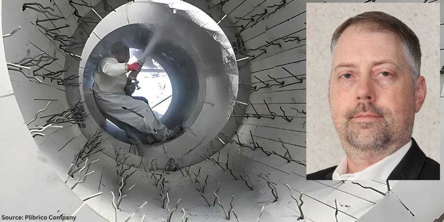
The faster the refractory installation, maintenance or repair, the more efficient and, by extension, profitable it is to the company, as savings fall to the bottom line. In this Technical Tuesday installment, Roger Smith, director of technical services at Plibrico Company, LLC, examines the challenges of insulation systems, taking a closer look at ultra-lightweight refractory gunite as a fast, flexible solution to controlling heat.
This informative piece was first released inHeat Treat Today’sFebruary 2025 Air/Atmosphere Furnace Systems print edition.
Manufacturers that rely on industrial grade furnaces, boilers and incinerators to produce their quality products are always looking for ways to improve. It is how they stay relevant and, more importantly, profitable. But you don’t get better just by desiring it. You need to identify better ways to get things done and introduce risk-neutral change to current operational processes. By some estimates, inefficient processes can reduce a company’s profitability by as much as one third.
Given refractories’ importance in safeguarding an operation’s multimillion-dollar thermal-processing equipment, and to avoid unscheduled downtime, it is smart business to have a sustainable maintenance and repair process in place. When a refractory situation does arise, the more proficient the process solution the better.
Controlling the Heat
Click the image above to read Roger Smith’s column on extending the life of refractory linings.
Furnace design is largely about controlling heat to maximize energy efficiency. An energy source — whether that is gas, coal, wood or electricity — is used to heat the furnace, and the furnace lining is designed to keep that heat inside the furnace. There are other factors to be considered, such as the environment inside the furnace, whether there is any abrasion or chemical interactions, or whether the furnace maintains a steady state temperature or undergoes temperature cycles. Regardless of what considerations have to be made for the hot-face lining, an insulation package must be used to reduce fuel consumption and control the cold-face temperature.
There are a large variety of insulation packages and materials that can be used in furnace design. Insulation comes in the form of board, fiber, brick and castables. Each type of insulation comes with its own sets of considerations, such as insulation value, installation method and cost. When considering the insulation package for the vertical wall of a furnace, support must also be considered because the insulation is expected to stay where it is placed and not slump over time. There also must be a means of connecting the hot-face working lining to the furnace structure to provide support. This is accomplished with an anchoring system that connects to the furnace shell and penetrates some distance into the dense hot-face working lining.
Anchoring Systems Challenge Insulation Installations
Anchors are considered to be the bones of a refractory installation and have several functions. They hold the refractory to the wall to keep it from falling in. They also prevent wall buckling due to the internal thermal stresses created by high temperatures. And, to a lesser degree, anchors can also help support the load of the refractory weight.
The anchoring system, however, can present big challenges when installing or maintaining the insulation. In most furnace applications, anchors are first welded directly to the furnace shell. Next, the insulation package is installed and finally the working lining. With anchors sticking off the furnace shell, installing insulation can become a challenge.
Fiber insulation in the form of blanket can be pressed into the gaps between the anchors, but it is important that the insulation remains in place during the life of the furnace. Industrial furnaces tend to vibrate, either from use of combustion or exhaust blowers or other process equipment. This constant vibration can cause fiber insulation to slump and lead to hot spots in the furnace wall due to the lack of insulation.
Figure 1. Anchoring systems are installed before refractory insulation and can pose challenges.
Insulation board is rigid enough to support itself on its end and can be found in a variety of densities and thicknesses to obtain the required insulation value. However, insulation board typically comes in sheets that will have to be cut to fit around the anchors. This can result in a significant amount of manpower and a significant amount of time in a furnace installation. The downtime of an industrial furnace can be costly, which often results in tens of thousands of dollars per hour in lost profits. For this reason, companies try to minimize the time spent rebuilding a furnace. Fewer man hours on a rebuild also tends to reduce the overall cost of the project.
Ultra-lightweight refractory gunites offer a means of installing a large amount of insulation in a relatively short period of time. A gunite is a monolithic refractory castable that is pumped dry through a hose under pressure and is mixed with water at the nozzle. Once the wet castable impacts the surface, it stiffens quickly to avoid slumping and hardens as it dries. This means that the gunite could be installed over the anchors with minimal time. The installer only needs to wrap the end anchors with masking tape to keep them clean for the working lining.
Figure 2. Cold-face and heat storage/loss graph for a production furnace
Distinct Differences in Refractory Gunites
Ultra-lightweight castables are a sub-set of the lightweight castables category but with a very important difference: density. For example, the average lightweight castable with a maximum service limit of 2400°F typically has a density of about 80–90 pcf (pounds per cubic foot). By comparison, ultra-lightweight castables with a maximum service limit of 2400°F will have a density of about 25–30 pcf.
This important distinction comes into play when looking at insulation thickness and calculating cold-face temperature. At the stated densities in a furnace operating at 2000°F, it would take nearly three times more lightweight castable than an ultra lightweight castable to achieve the same cold-face temperature — making many ultra-lightweight castables perfect for insulation and most lightweight castable refractories impractical to use as part of the total insulation package.
Ultra-lightweight castables that achieve final densities of 25–30 pcf while offering service temperatures above 2400°F are available through various refractory manufacturers. One such product, Plicast Airlite 25 C/G (aka Liquid Board) from the Plibrico Company, is designed to be installed via casting or gunite using conventional gunite equipment. With low thermal conductivity and thermal-shock resistance, this material is durable and quick to install. It also has advantages over insulation board, which has a labor intensive installation process of cutting around all the welded anchors, and fiber insulation, which can experience frequent hot spots due to slumping insulation. With an ultra-lightweight, Liquid Board-type of castable, it is possible to attain required insulation values and extended lining life with the installation speed of a refractory gunite.
Working With, Not Against, the Anchoring System
Let’s consider a real-life production furnace operating at 2000°F with a simple 9-inch refractory lining consisting of six inches of dense refractory and three inches of insulation. For comparison, we will assume an ambient air temperature of 81°F and eliminate any effects of exterior wind velocity. The dense refractory working lining for these examples is Pligun Fast Track 50, a 50% alumina, 3000°F-rated refractory gunite.
As seen in Figure 2:
Using three inches of ceramic fiber blanket at a density of 6 pcf, a cold face temperature of 252°F can be achieved.
Using three inches of insulation board at a density of 26 pcf, a cold face temperature of 247°F can be achieved.
Using three inches of an ultra lightweight gunite such as Plicast Airlite 25 C/G with a maximum service temperature of 2500°F and assumed density of 25 pcf, a cold-face temperature of 262°F is expected.
The calculated difference in cold-face temperature between insulation board and the ultra-lightweight gunite is 15°F, but the difference in installation time savings could be multiple shifts.
Figure 3. Ultra-lightweight gunite is quickly applied over anchors with standard equipment.
The cost of downtime can be incredibly high for any manufacturer, especially since downtime can result in a series of costs and losses (both tangible and intangible), including production, labor, replacement costs, product losses and, if unexpected, reputation damage. Industry resources estimate downtime can cost thermal processing companies between $250,000 and $1 million per hour. When multiplied over several shifts, this could mean millions of dollars in downtime costs. Not to mention that labor is a major contributor to the overall cost of a refractory project. The quicker the refractory installation, the less downtime and the more profitable the company.
For example, in an approximately 750-square-foot round duct application (cylinder) with anchors already installed, on average, installation of four inches of the different insulation types can be estimated at:
Fiber Insulation — 137 total labor hours, or ~5.5 square feet/hour
Insulation board — 288 total labor hours, or ~2.6 square feet/hour
Ultra-light gunite/Liquid Board — 80 total labor hours, or ~9.4 square feet/hour
The quick and easy installation of the ultra-light gunite/Liquid Board represents an average estimated financial savings in downtime of between $35 million and $130 million — savings that drops directly to a company’s bottom line. The time compression of installing gunite also holds an added advantage for the insulation installer because labor hours can come with a premium price tag and can sometimes be in short supply. All of this makes the ultra-lightweight gunite solutions an excellent choice to minimize downtime and rebuild costs while meeting the furnace design criteria.
Conclusion
Manufacturers that rely on industrial-grade furnaces, boilers and incinerators to produce their quality products are constantly looking for ways to reduce costs, increase profits and improve efficiencies by looking at and introducing risk-neutral change to current processes. Maintaining efficiency and avoiding unscheduled shutdowns of heat processing equipment requires maintenance. Selecting quality materials and risk neutral installation processes that minimizes maintenance completion times can help companies become more efficient.
About the Author:
Roger M. Smith Director of Technical Services Plibrico Company, LLC
Roger M. Smith, a seasoned professional in the refractory industry, is the director of technical services at Plibrico Company, LLC. With a master’s degree in Ceramic Engineering from the University of Missouri — Rolla, Roger has over 15 years of experience in the processing, development and quality assurance of both traditional and advanced ceramics. He has a proven track record in developing innovative ceramic formulations, scaling up processes for commercial production, and optimizing manufacturing operations.
The heat treating industry is under pressure to reduce its greenhouse gas emissions (GHGE), and the response has been a noble effort to attain sustainability. In 2024, Heat Treat Today published a series of articles by guest columnist Michael Mouilleseaux, general manager at Erie Steel, Ltd., regarding the U.S. Department of Energy’s initiative related to the decarbonization of industry and its potential impact on the heat treating industry.
This update was first published in Heat Treat Today’s February 2025 Air & Atmosphere Heat Treating Aerospace print edition in response to recent changes in the U.S. administration.To catch up on previous columns by Mike, check these out: “US DOE Strategy Affects Heat Treaters“ appeared in the March 2024 Aerospace print edition; “U.S. DOE Strategy: Ramifications for Heat Treaters” appeared in the May 2024 Sustainability print edition; and “US DOE Strategy: Why the Heat Treating Industry?” appeared in the June 2024 Buyer’s Guide print edition.
As described in previous articles, President Joe Biden issued an executive order in 2021 that committed the federal government through the Department of Energy (DOE) and the Environmental Protection Agency (EPA) to reduce GHGE attributable to “process heating” by 85% by 2035 and attain net zero CO2 emissions by 2050.
These goals were to be achieved by implementing four largely unproven technologies:
Energy efficiency
Industrial electrification (using green electricity)
Adoption of low-carbon fuels (e.g., hydrogen), feedstocks, and energy sources (LCFFES)
Carbon capture, utilization and storage at the generated source (CCUS)
On www.heattreattoday.com/factsheetDOE, you can utilize the one-page resource to let governmental officials know what our industry is, who we are, who we employ, and the effect this effort has in regulating us out of business.
We further described the negative effect the implementation of these efforts would have on the heat treating industry — specifically, an increase in energy costs from 4x to 15x, with a companion reduction in energy reliability. This is not the combination that portends success in business.
In November of 2024, the people of the United States made a statement. They decided the direction of the country for the past four years was not what they wanted and chose another path, a path they chose based on what they had experienced from 2017 through 2020. As it pertains to industrial policy, they knew that reduced regulation and policies favorable to business growth were the guiding principles.
What may we reasonably expect from a Trump administration relative to this Industrial Decarbonization Effort?
At a minimum, we should expect a sober understanding of the issues and agreement that any low-carbon replacement energy technologies will come with the assurance they are cost competitive with current sources, and that they will be reliable and secure.
Is this to say that all efforts toward the achievement of a reduction in greenhouse gas emissions (GHGE) should be abandoned? Absolutely not, however, they should not be implemented with a religious zeal that places implementation above practicality. We need to recognize that if our way of life is to be maintained, these changes will be evolutionary — not revolutionary.
Should we anticipate this effort to revise the “timing” of GHGE reductions will be easy to achieve? It will not; the Biden administration has made every effort to obligate a maximum amount of the funding from the IRA earmarked for “clean energy,” understanding any funds not so obligated can be rescinded. Additionally, a concerted effort to place these funds in Republican states was made to make any recission as politically painful as possible for the incoming administration.
The incoming administration has made it clear they will scrutinize all existing funding sources that support those clean energy initiatives that distort and undermine energy independence and reliability. They have stated they intend on immediately pausing all regulatory activities until they have the opportunity to review them. They intend on rescinding all executive orders that further the clean energy agenda.
Do we have a part in this? Yes, our industry, although crucial to the manufacturing community and national security, has very little visibility. Now is the time to act and to let our representatives and senators know how important it is to pause, if not reconfigure, this Industrial Decarbonization Initiative to assure our businesses remain vibrant and vigorous.
Attend the 2025 SUMMIT to find out more about the DOE’s actions for the heat treat industry.
About the Author:
Michael Mouilleseaux General Manager Erie Steel, Ltd
Michael Mouilleseaux is general manager at Erie Steel, Ltd. He has been at Erie Steel in Toledo, OH since 2006 with previous metallurgical experience at New Process Gear in Syracuse, NY, and as the director of Technology in Marketing at FPM Heat Treating LLC in Elk Grove, IL. Michael attended the stakeholder meetings at the May 2023 symposium hosted by the U.S. DOE’s Office of Energy Efficiency & Renewable Energy.
The Heat Treat Doctor® has returned to offer sage advice to Heat Treat Today readers and to answer your questions about heat treating, brazing, sintering, and other types of thermal treatments as well as questions on metallurgy, equipment, and process-related issues.
This informative piece was first released in Heat Treat Today’sFebruary 2025 Air/Atmosphere Furnace Systems print edition.
People often ask two fundamental questions related to normalizing. First, is it necessary? Second, just what and how important is a “still air” cool to the end result? Let’s learn more.
Why Normalize?
Contact us with your Reader Feedback!
Normalizing is typically performed for one or more of the following reasons:
To improve machinability
To improve dimensional stability
To produce a homogeneous microstructure
To reduce banding
To improve ductility
To modify and/or refine the grain structure
To provide a more consistent response when hardening or case hardening
For example, many gear blanks are normalized prior to machining so that during subsequent hardening or case hardening dimensional changes such as growth, shrinkage, or warpage will be better controlled.
Normalizing imparts hardness and strength to both cast iron and steel components. In addition, normalizing helps reduce internal stresses induced by such operations as forging, casting, machining, forming or welding. Normalizing also improves chemical non-homogeneity, improves response to heat treatment (e.g., hardening), and enhances dimensional stability by imparting into the component part a “thermal memory” for subsequent lower temperature processes. Parts that require maximum toughness and those subjected to impact are often normalized. When large cross sections are normalized, they are also tempered to further reduce stress and more closely control mechanical properties.
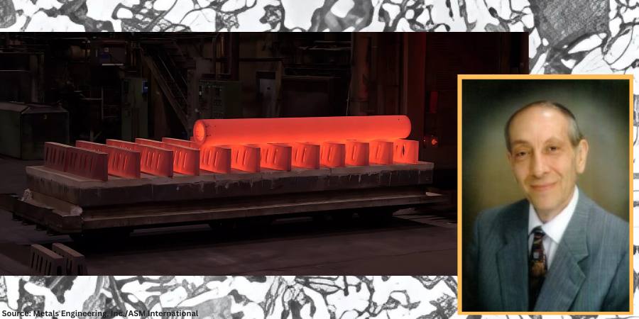
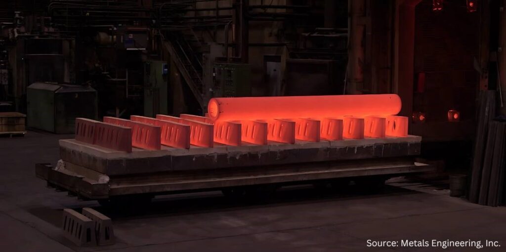
Large paper roll normalized in a car bottom furnace and cooled (due to its mass) using the assistance of a floor fan.
Soak periods for normalizing are typically one hour per inch of cross-sectional area but not less than two hours at temperature. It is important to remember that the mass of the part or the workload can have a significant influence on the cooling rate and thus on the final microstructure. Thin pieces cool faster and are harder after normalizing than thicker ones. By contrast, after furnace cooling in an annealing process, the hardness of the thin and thicker sections is usually about the same.
Micrograph of medium-carbon AISI/SAE 1040 steel showing ferrite grains (white etching constituent) and pearlite (dark etching constituent). Etched in 4% picral followed by 2% nital. (Bramfitt and Benscoter, 2002, p. 4. Reprinted with permission of ASM International. All rights reserved.)
When people think of normalizing, they often relate it to a microstructure consisting primarily of pearlite and ferrite. However, normalized microstructures can vary and combinations of ferrite, pearlite, bainite, and even martensite for a given alloy grade are not uncommon. The resultant microstructure depends on a multitude of factors including, but not limited to, material composition, part geometry, part section size, part mass, and cooling rate (affected by multiple factors). It is important to remember that the microstructure achieved by any given process sequence may or may not be desirable depending on the design and function of the component part.
The microstructures produced by normalizing can be predicted using appropriate continuous cooling transformation diagrams and this will be the subject of a subsequent “Ask The Heat Treat Doctor” column.
In this writer’s eyes, industry best practice would be to specify the desired microstructure, hardness, and mechanical properties resulting from the normalizing operation. Process parameters can then be established, and testing performed (initially and over time) to confirm/verify results.
In many cases, the failure of the normalizing process to achieve the desired outcome centers around the lack of specificity (e.g., engineering drawing requirements, metallurgical and mechanical property call outs, testing/verification practices, and quality assurance measures). Failure to specify the required microstructure and mechanical properties/characteristics can lead to assumptions on the part of the heat treater, which may or may not influence the end result.
“Normalizing is the heat treatment that is produced by austenitizing and air cooling, to produce uniform, fine ferrite/pearlite microstructures in steel … In light sections, especially in alloy hardenable steels, air cooling may be rapid enough to form bainite or martensite instead of ferrite and pearlite.”
What Is Normalizing?
The normalizing process is often characterized in the following way: “Properly normalized parts follow several simple guidelines, which include heating uniformly to temperature and to a temperature high enough to ensure complete transformation to austenite; soaking at austenitizing temperature long enough to achieve uniform temperature throughout the part mass; and cooling in a uniform manner, typically in still air” (Herring, 2014).
It is also important to remember that normalizing is a long-established heat treatment practice. As far back as 1935, Grossmann and Bain wrote:
Normalizing is the name applied to a heat treatment in which the steel is heated above its critical range (that is, heated to make it wholly austenitic) and is then allowed to cool in air.
Since this is one specific form of heat treatment, it will be realized that the structure and mechanical properties resulting from the normalizing treatment will depend not only on the precise composition of the steel but also on the precise way in which the cooling is carried out.
The term ‘normalizing’ is generally applied to any cooling ‘in air.’ But in reality, this may cover a wide range of cooling conditions, from a single small bar cooled in air (which is fairly rapid cooling) to that of a large number of forgings piled together on a forge shop floor … which is a rather slow cool, approaching an anneal. The resulting properties in the two cases are quite different.
In plain carbon steels and in steel having a small alloy content, the air-cooled (normalized) structure is usually pearlite and ferrite or pearlite alone … More rapid cooling gives fine pearlite, which is harder; slow cooling gives coarse pearlite, which is soft. In some few alloy steels, the normalized structure in part may be bainite.
The hardness of normalized steels will usually range from about 150 to 350 Brinell (10 to 35 Rockwell C), depending on the size of the piece, its composition and hardening characteristics.
Importance of Defining Cooling Rate
In 2005, Krauss underscored the importance of defining cooling rate when he wrote: “Air cooling associated with normalizing produces a range of cooling rates depending on section size [and to some extent, load mass]. Heavier sections [and large loads] air cool at much lower cooling rates than do light sections because of the added time required for thermal conductivity to lower temperatures of central portions of the workpiece.”
Microstructures Created by Normalizing
The microstructural constituents produced by normalizing for a particular steel grade can be ferrite, pearlite, bainite, or martensite. The desired microstructure from normalizing adds an important cautionary note, as addressed by Krauss in STEELS (1990 and 2005), namely: “Normalizing is the heat treatment that is produced by austenitizing and air cooling, to produce uniform, fine ferrite/pearlite microstructures in steel … In light sections, especially in alloy hardenable steels, air cooling may be rapid enough to form bainite or martensite instead of ferrite and pearlite.”
Next time: We define a “still air” cool and look at the state of normalizing in North America.
Practical Data for Metallurgists, 17th ed. TimkenSteel.
Totten, George E., ed. Steel Heat Treatment Handbook, vol. 2, 2nd ed., CRC Press, 2007. 612-613.
About the Author
Dan Herring “The Heat Treat Doctor” The HERRING GROUP, Inc.
Dan Herring has been in the industry for over 50 years and has gained vast experience in fields that include materials science, engineering, metallurgy, new product research, and many other areas. He is the author of six books and over 700 technical articles.
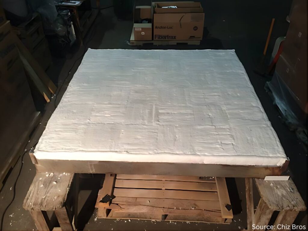
In this Heat TreatRadioepisode, Mark Rhoa, Jr. from Chiz Bros, a company specializing in ceramic fiber products, discusses insulation with host Doug Glenn. Mark focuses on the benefits of ceramic fiber in industrial applications. The conversation covers decarbonization, the importance of insulation and thermal shock resistance, the shift to electrically heated modules, and practical maintenance tips for ceramic fiber-insulated furnaces.
Below, you can watch the video, listen to the podcast by clicking on the audio play button, or read an edited transcript.
Doug Glenn:I want to welcome our guest today: Mark Rhoa Jr. from Elizabeth, Pennsylvania, near Pittsburgh. Mark’s been involved with the industry for quite a while with Chiz Bros, our sponsor for today. Mark is also aHeat TreatToday40 Under 40honoree from the Class of 2021. And, Mark, could you tell me who started your company — your dad or your dad and his brother? I don’t know the history that well.
Mark Rhoa: My dad actually joined the company in ‘97, but when he joined, Chiz Bros. had been around for a good 30 years or so. It was started by the Chiz brothers originally: Al, Ray, and John Chiz. As they got older and some of them moved on from the company to retire, my dad took over the company in 2014, and that’s when I came on board.
I’ve been here about ten years. And Ray Chiz Jr. just recently retired; he is one of the original owners’ sons who was working here running our warehouse. He’s the last with the Chiz name to work here. We say that the Chiz haircut is kind of what I’ve got going on. You can know by the haircut there’s a lot of Chiz’s still working here, and you might even be an honorary.
Doug Glenn: I can be an honorary, for sure. I don’t have enough on the side.
Chiz has been around for 50 some years doing specialty solutions for refractory applications in the metals, power, glass, and ceramics industries. And you guys deal with multinational companies as well as the small Ma and Pa shop furnace manufacturers or heat treaters/thermal processors, a pretty good mix. You’ve got great customer service, reasonable pricing, and quick delivery. And I know you and I have talked about how you guys pride yourselves on having a lot of stuff in stock. And finally, you guys have your Pittsburgh location and are also in Detroit, which is a relatively new addition, right?
Mark Rhoa: Yeah, about two years ago we opened up a Detroit warehouse. We’ve always had some good clients up that way. You’ve got to have some boots on the ground to be super effective. I say to get the easy orders you’ve got to have the stuff on the ground to get the hard orders, which are the phone calls at 5 o’clock on a Friday saying, “Hey, we need to pick this up because the furnace is down.” And we didn’t have that opportunity to improve our customer service up there before opening that location.
We try to punch above our weight to compete with the big guys on pricing. We make sure we’re always still answering the phone.
Doug Glenn: It makes a huge difference when you’ve actually got people answering the phone.
My understanding is that you provide castables, fibers, brick, etc. But today we want to hone in a little bit on ceramic fiber.
Mark Rhoa: Ceramic fiber is the big portion of our business. We’re one of the biggest Unifrax (Alkegen) ceramic fiber distributors in the country. So, a lot of what we do is being driven by ceramic fiber products we supply. We still can supply castables, bricks, and everything in between. But ceramic fiber drives the ship for us.
What Is Ceramic Fiber? (04:58)
Doug Glenn: Let’s talk about that. Most of our listeners are folks with their own in-house heat treat. But let’s assume we’ve got some people watching that don’t know some basics.
Tell us about ceramic fiber: What is it? How is it made? What are we using it for?
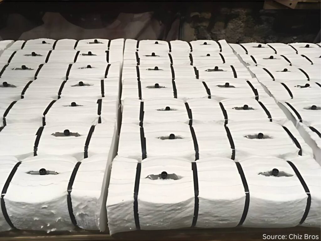
Mark Rhoa: I describe it to people who may not know much about it by comparing it to the Pink Panther insulation that people may recognize up in their roof or in their walls. Ceramic fiber is white, but picture that insulation for 2300°F. That’s what ceramic fiber is, and it’s a form that we sell the most of right now.
Ceramic fiber
You can take that and cut gaskets out of it. You can form it into hard boards through a vacuum forming process. You can take it folded into what we call ceramic fiber modules; your furnace probably has modules in it if it’s a traditional gas-fired or electric furnace. Ceramic fiber products typically aren’t used on the vacuum side of things. People with all vacuum furnaces are probably not going to be using ceramic fiber. There are cloths that are ceramic fiber based as well. There’s a bunch of other ways it’s used.
Ceramic fiber is made of a blown, spun glass. Essentially what you’re doing is dropping the liquid aluminum silica mixture, and it gets blown or blown and spun at super high temperatures. I’m not going to get into the details of the differences there, but whether the stream is blown or is spun on wheels will determine the tensile strength of blanket.
In the grand scheme of things, what you’re doing is collecting all that fiber and getting it onto a mechanism that’s moving along a conveyor belt. Then it’s getting needled from each side to interlock the fibers to make a 26” wide blanket. It’s going to be trimmed off an inch when it goes through, and at the end you have a 24” wide x 1” thick, 8-pound density roll coming out.
Those densities can vary based on how much fiber is going into it. It’s pounds per cubic foot. But when you’re using a 1” thick piece, it’s divided by twelve from a weight standpoint. The fiber you’re needling in there determines the density.
And there are slightly different chemistries for 2300°F, 2600°F, and the most expensive would be 3000°F polycrystalline. The process to make that is a little bit different, too.
But most people are probably more interested in what we’re doing with it. What’s the Chris Farley line in Tommy Boy? We’ll keep it PG, but “take a butcher’s word for it” — take our word for it; it’s made the right way.
Now we can get into how it’s actually used.
Doug Glenn: It’s basically like insulation in your house, like you said. That’s probably the best description of it for people that need to know. But it can obviously go to a much higher temperature.
In an industrial setting, why would you use fiber versus a castable or brick?
Why Fiber? (08:28)
Mark Rhoa: Ceramic fiber is a great insulator. We’ll probably get into why a better insulator is important for decarbonization efforts and things like that.
It’s certainly a better insulator than castables, easy to install, and easy to use. The main reason it’s preferred is for its insulating value and ability to have varying temperature ranges, which you can certainly do with castables and brick.
But to put brick in a wall 12” thick, for argument’s sake, you will need four layers of 3” brick on there. With ceramic fiber, you can take one 12” x 12” module, shoot it onto the shell, attach it, and be good to go from there.
The main thing would be longevity and stuff like thermal shock value. One of the things you have to worry about with castables and brick — maybe not as much with IFB but standard brick — is the heat cycling. Heat treat furnaces are a great example of that.
That door is opening up a lot, so the air is coming in there. People probably see it in their furnaces. The castable is going to want to crack because it’s not designed for thermal shock like ceramic fiber is.
There are certainly applications that you wouldn’t want to use ceramic fiber for. If you’re looking at a traditional heat treat furnace, it depends on how the load is supported: If the floor is the refractory, it is actually supporting the load, and you’re going to want some sort of brick, some sort of castable. Fiber is going to be soft, compressed, and get beat up. You can’t necessarily put it everywhere, but there are areas where it may be up for debate on.
You can use a brick or you can use fiber in the wall. Traditionally, you’re going to use fiber for the insulated value, thermal shock value, installation, and weight; it’s a lot lighter.
A lot of heat treating furnaces are small compared to the massive furnaces in steel melting. They’re going to ship heat treating furnaces. With ceramic fiber, a 12” x 12” fiber module, 12” thick, weighing roughly 12–14 lbs. is 5–10x lighter than brick or castable.
Repairability (10:51)
Doug Glenn: How about addressing the repairability issues between castable and brick and fiber?
Mark Rhoa: Fiber, especially if you’re getting into higher temperatures, can have some shrinkage to it. But you’re able to repair fiber a lot easier. If you wreck a little bit of fiber, you can get in there and get it repaired quickly. With a brick or castable everything’s tied together as either a monolithic piece or a bunch of bricks that are connected, it can start to become a house of cards scenario where you pull and one goes down then everything goes down.
Doug Glenn: It’s like a Jenga game. You pull that brick out on the bottom and what happens?
Figure 2. “You don’t want to pull out the wrong brick.”
Mark Rhoa: Yeah, you don’t want to pull the wrong brick.
Doug Glenn: You already mentioned the temperature ranges we’re talking about. The standard bottom temperature is 2300°F; the fibers are good up to 2300°F. Then you’ve got 2600°F and then 3000°F. Is that roughly the breakdown when you’re looking at fibers?
Mark Rhoa: I don’t know why they ended up doing this, but for 2300°F ceramic fiber, realistically you only want to use it to 2150°F. That goes along with the shrinkage curve of it. I forget the exact number, but I think it’s like in 24 hours, you get less than 3% shrinkage. Typically, the rule of thumb is that you don’t want to use that full temperature range; you want to give yourself 150°F of cushion to be safe. It will still have shrinkage after that up to that temperature.
I don’t know who ever thought of that; it was probably some genius marketing guy to get a little extra.
Fiber Shrinkage (12:57)
Doug Glenn: You’ve mentioned shrinkage a couple different times. Why does that happen with ceramic fiber? And how does that impact installation?
Mark Rhoa: When ceramic fiber hits its operating temperatures, it shrinks up. On the chemistry side, I don’t have an answer there. But we factor in compression to help alleviate when something shrinks. It’s already pushing out against something. It still keeps its resiliency (it wants to pop back out), and that’s factored into every design.
If you’re doing 12” modules, you’ll have a batten strip between them. That makes up for some of the shrinkage that may come where there’s not compression. Any sort of design we would do, or probably anyone would do, is going to factor in shrinkage. You don’t want to just put something in there, and when it shrinks, it leaves a gap. You want to make sure you have something in there that’s going to fill that gap; and that’s typically for modules.
Now if you’re getting to a low temperature, we’re talking about a furnace at 1200°F, you’re not going to have to worry about shrinkage. Even in some of those furnaces, you’ll see designs we call wallpaper — a pin’s exposed and you’re layering on top of it. You’re just kind of overlapping gaps, but you’re not going to have any shrinkage there, so you don’t really have to worry.
Figure 3. Avoiding gaps when shrinkage occurs
Doug Glenn: There is one question I did want to ask you when we were talking about the different temperature ranges of 2300°F, 2600°F, and 3000°F. Are the chemistries between those different?
Mark Rhoa: They’re all alumina silica based. 2300°F is like 50% alumina and 40% silica. They’ll typically inject some zirconia in it, maybe around 15% zirconia. That gives it the extra boost. Alumina is what drops down.
We don’t want to get into every example, but it does have a lower aluminum content. Sometimes in aluminum melting you can get some flexing because there’s zirconia in there, so you need to know the exact application.
And then the polycrystalline, what people call the 3000°F, would be 72% alumina. And that’s made in a calcined process. The 72% alumina is the key factor.
You can also have super high aluminum blankets. Saffil® is the typical brand name. And that’s a 95% plus alumina. That’s for high hydrogen atmospheres, stuff where there’s bad attacking, bad off gassing. The alumina is usually more resilient to that. Some aerospace applications have that stuff spected in for effectiveness and also because they probably have government money. Why not pay for the highest quality, most expensive thing, right?
Electric Element Modules (18:32)
Doug Glenn: You mentioned modules before, but I want to take a little bit of a different angle. The modules you were talking about have no type of heating element in them. They’re just simply the insulating modules that you put on the side of the wall, side by side, maybe alternating the orientation. But what I want to talk about are electric element modules. Can you describe what those are and why you are using them? And maybe hit on the decarbonization or electrification element of those?
Mark Rhoa: Traditional fiber modules are used in a gas furnace, even an electric furnace that may be heated by glow bars or radiant tubes or something like that. That’s going to have a similar penetration there.
One of the systems we call our ELE system. I’d say in the last two years we’ve probably had as many inquiries or conversations about going to these electrically heated modules than we have in the past 5–10 years combined. A lot of that has to do with companies wanting to get away from gas, or they’ve got pressures for different environmental or cost saving reasons.
What we’re doing with that is hanging the elements on the ceramic fiber module. And when they show the pictures of this one, there’ll be one in there. But that allows us to do a modular system where they can get a lot of power on those walls, and it lets us keep a lot of the same insulating value from using modules without having to use brick or a super heavy element in the sidewalls for support.
Electric Element Modules
When someone says we’re putting this many BTUs of gas; here’s the load, size, weight. We do the electric calculations to see how many kilowatts of power we need to pump into this furnace and elements in order to heat something up just like you would do with gas.
And rest assured, someone a lot smarter than me does those calculations. I’m just a pretty face that gets to sell them. But this is something that we’re seeing a lot of. There’s a big push coming from the government and boards of directors.
Doug Glenn: It’s going to help companies reduce their carbon footprint if that is their desire.
I have a question for you about those and specifically about installation. If every module needs a power source, do you have to punch a hole in the furnace wall for every module, or can you interlink them and only have one power source at the end of the chain?
Mark Rhoa: Good question. I didn’t do a good job describing that, but the modules will still go in just like a regular module. They actually have an extra set of ceramic tubes in them. When we do our design, we know where the elements are going to be hung.
If you have a 10-foot wall, you’re not going to have ten 1-foot pieces of element. You’re going to have an eight foot string of elements along that wall, and they will be hooked into the loops. One end of the hook will go on a loop, the other end will go on the ceramic tube that’s inside the module.
If you have a 12’ x 12’ high wall, and you may have a 10’ element in there, you’re probably only going to have four penetrations, maybe more. It’s not going to look like Swiss cheese. They’re going to be linked together.
These are all based on the number of zones in a furnace, too. Some super high aerospace applications are going to have everything super fine tuned just like it is with burners. If you think about how certain applications require way more precision and control over burners, the same thing can be true for these elements, too. The more precision and control you need, the more complicated it’s going to be just like it is with burners.
Before you hang the elements, you could look in that furnace and it would look just the same as a regular gas-fired furnace without the burners. Then you start hooking the elements on the walls. And the pictures of it are helpful.
If anyone has seen Home Alone, he goes into his basement and his furnace is shooting out all the flames. If you walk into a plant and can see that, getting that to seal will prevent heat from leaving.
Mark Rhoa
Furnace Doors (23:52)
Doug Glenn: When I think about ceramic fiber (which you don’t often see it inside a furnace if the door is closed), but a lot of times you’ll see it jammed in around the doors. To me it doesn’t look like that’s the way it’s supposed to be. So, doors are an issue, right? Can ceramics help with that?
Mark Rhoa: In heat treating furnaces, the temperatures aren’t totally crazy like forging furnaces where there’s a lot of shrinkage so they’re replacing it all the time. In heat treat, the temperature is lower. The main wear and tear items we see when we’re working on a repair with a client are around the doors because they’re getting the mechanical abuse of constantly changing. In some of the decarbonization talks I’ve attended and given at trade shows, we’re really looking at ways to save heat. Just making sure your door is sealed properly can do wonders.
If anyone has seen Home Alone, he goes into his basement and his furnace is shooting out all the flames. If you walk into a plant and can see that, getting that to seal will prevent heat from leaving.
You hear all these decarbonization talks, you see all these millions of dollars being thrown around, and, really, you can make a huge difference on a shoestring budget by simply making sure your door is sealing the way it’s supposed to seal.
If you can see the heat coming out, it’s like dollars flying out of your furnace on a game show. You’d have people lined up for that every day of the week.
So you hit the nail right on the head there. A really small, easy way to make a calculated decarbonization effort is making sure you have a door plan or you’re changing it.
It’s the same thing with tuning burners. Little tunes to a burner can save tons of gas and tons of CO2.
Figure 5. Heat leakage from doors needing maintenance
Doug Glenn: Making sure you’re maintaining good flame curtains on a continuous furnace, all that stuff just keeps the heat from coming out.
Did I see correctly that you guys do door repairs?
Mark Rhoa: We’ll do door repairs in our own shop. If someone ships a door to us, we’ll do the realigns there. About 20 years ago, we stopped having our outside contracting arm. Now we’re not doing any of the fieldwork. But we do realign doors in our shop.
Fiber is pretty easy to work with. Door perimeters are something that can easily be done by someone’s own maintenance crew. Maybe they’ll need one of our sales guys there making sure they do it right the first couple times. But it’s not a hard thing to do. If you have a 12 inch module perimeter, switch those 40 modules out once a year and you’ve got fresh gas savings.
Ceramic Maintenance (27:07)
Doug Glenn: Let’s shift gears a bit and talk about typical maintenance of ceramic-insulated furnace. What do we need to be careful about? Any tips you can offer?
Mark Rhoa: There’s another really affordable thing you can do. You can probably sometimes see this if you have a hot spot where paint’s chipping off or melting or if you have a temperature gun you can find those hot spots. If you see heat on the outside, then you’re typically going to see some sort of crack or gap on the inside. Make sure you have scheduled maintenance downtime with your furnace and stuff in any of those cracks.
If you’ve got a really big furnace or a continuous furnace, roller hearth, furnace type thing, the roll seals are some of the areas where you’re going to end up losing a lot of heat because there’s more wear and tear there. There’s just more opportunity for expansion and contraction.
We do have ceramic pumpable products. We call it liquid ceramic fiber for when there’s a hot spot on a furnace, it’s a big one, and you can’t get in there, you can drill a little hole on it, pump it in from the backside, and fill that up. You don’t want to start making your furnace Swiss cheese and poking holes.
It can be a quick stopgap. If you can’t get inside the furnace, fill it in from the backside, too. Because you don’t want those hot spots to grow and cause problems. You don’t want them to get to the hardware.
Then you may have a module where the hardware gets too hot in the backside and the module ends up falling in. That’s one scenario. You can get out ahead of it by filling some of those gaps.
For a refractory on the hearth, too, if you don’t want to replace a hearth you can find a refractory contractor to come in and (if you have a big furnace) spray gunite over the hearth to fix any gaps or cracks.
Doug Glenn: That’s more for castable, though?
Mark Rhoa: Yeah. On the fiber side of things, you’re looking for hot spots.
Doug Glenn: The takeaway is to make sure you’re taking regular thermal imaging of your shell of the furnace. If you’re noticing some hot spots, it’s time to investigate.
Mark Rhoa: If you have a lot of furnaces, you can get a thermal imaging gun for a couple hundred bucks and really [keep an eye out].
An even bigger deal are the doors. It will blow your mind if you look at the temperatures on a fresh door seal versus an old one. Have a temperature gun to justify to your bosses. “Hey, we realigned this, and it is 150°F. This time last year it was 250°F–350°F degrees.” Common sense can tell you we’re losing more heat when it’s like that.
Concerns with Free Floating Fiber (30:20)
Doug Glenn: Can you address the concern that some furnace users have regarding free floating fiber, especially in furnaces where there’s high velocity airflow?
Mark Rhoa: Talking about the benefits of fiber versus brick and castable, one of the benefits of the hard refractory is it does better with high velocities. Patriot furnaces may have a fan in there. Typically, they’re not getting high enough where we need to worry. You can put coatings on the fiber or rigid dyes or things like that to harden them.
But from a health and safety perspective, anytime you’re working with fiber you want to make sure you’re wearing a mask. They have warning labels on them. It’s not like it was back in the day. I’m not allowed to say the “a” word [asbestos]. So there are not worries like that anymore, either. But refractory ceramic fiber still does have a warning label on it.
We do have body size soluble fiber. Alkaline earth silica (AES), non RCF fiber, a bunch of fancy names, are more prevalent in Europe because of their rules. California’s got a lot of rules, too….
But we do supply that as well. It doesn’t have any sort of warning labels on it.
Obviously, when you’re working with it, you want to wear a mask because dust in general isn’t good. But it’s naturally soluble for your body.
It’s not quite as strong. It can have more shrinkage at lower temperatures. But it’s best to talk with somebody and understand what the right product is to use. Things can be a little worse, but there is a slight move in the direction of body soluble fiber because there are no warning labels on it. But it’s not drastic.
Some of the similar concerns foundries have is with sand and airborne silica now. Technically, I guess going to the beach we’d have airborne silica, too. There’s justification to taking those precautions, but it’s certainly not all doom and gloom.
The ceramic fiber is essentially little glass beads, like a tadpole head and then there’s a fiber tail that interlocks.
Mark Rhoa
Doug Glenn: What I heard wasn’t so much a human safety issue. It was the use of ceramic blankets inside of an aluminum annealing furnace: If the fibers got airborne, they would come to rest on the coils and mess up the strip going through. And then you have contaminated coil or it’s marked.
Mark Rhoa: The issue with that is the shot on the fibers. The ceramic fiber is essentially little glass beads, like a tadpole head and then there’s a fiber tail that interlocks.
Fiber has come a long way. The shot content is way lower than it used to be. But it’s certainly a concern if that gets on a coil and then it goes through the rolling mill and you make a small dent in all the glass … yeah.
A lot of different things can be done for that. People put up cladding; people rigidize it to lock the fiber in.
There are definitely concerns for all the applications. Big aluminum homogenizing furnaces may have that. Traditional, smaller batch annealing furnaces may not.
It would be the same thing if a little piece of brick chipped off onto [indiscernible]. The worry with some of the fiber stuff is it’s obviously a lot smaller so you don’t get to see it.
Doug Glenn: It’s a lot more conducive. You can imagine the difference between a brick being hit with high velocity air and a fiber, you would just see the degradation of the fiber. A fiber ceramic blanket would go down quicker.
Induction at Chiz (35:20)
I have one other question for you about Chiz. Your company was one of our sponsors at our recent Heat TreatBoot Camp, and I was surprised when you had an induction coil on your table. If you don’t mind, address what it is Chiz is doing in the induction area?
Mark Rhoa: We were using the company down the road from us, Advanced Materials Science (AMS), to machine some of our fiber boards and bricks that were a little too complicated for what we had in-house at the time. They have some really good CNC equipment up there. The guy who owned AMS was looking to sell off that branch of his business. We had been one of his bigger clients, and we came to an agreement to it; it’s still out of the same building, same equipment, same guys that are doing all the good work.
We started getting in there and saw a lot of the induction heating equipment on the client list — a lot of those electrical plastics, high temperature plastics, electrical marinite and transite boards, which we got into a little bit in the Chiz Brothers world but didn’t fully dive into it because the temperatures are a little bit lower than what we’re dealing with on the ceramic fiber side of things.
It’s been really good for us. They’ve got great machining capabilities down there to machine some of these complex parts out of NEMA G10 and marinite and transite and all these terms that were relatively new to me when we bought them.
It’s really helped us at some of these trade shows because three types of furnace guys walk by: the gas-fired guy, he’s my best friend; the induction guy used to be like, “There’s not that much we can do with you.” Now, we can do a lot with them.
And then I’m still trying to figure out how I can be happy when the vacuum furnace guy walks by. That will be a different battle for a different day. I’m not trying to get into the graphite felt world. I probably just can’t be friends with everybody.
But it’s been good to get into the induction industry. It’s something that we’ve been growing over the last year or two because we hadn’t been engaged with people quite as much as we had.
Doug Glenn: Well, we’ll look for opportunities for you to be friends with the vacuum people. One thing I know from experience, Mark, you could be friends with anybody. I’m sure you can work it.
Mark Rhoa: I’ll try my best.
Doug Glenn: You’re doing good.
Thanks so much. I appreciate your time and appreciate you being here.
Mark Rhoa: Look forward to seeing you at the next event. For anyone watching, Heat TreatBoot Campwas great. Whether you’re a supplier or heat treater, it’s a good group of people bouncing ideas. It’s a crash course on a hundred different things in two days. I was there to sell stuff, but I learned stuff, too, which was an added bonus. I’d recommend it to anyone watching. It’s a good way to force yourself to get out of the office. I will definitely be back.
Attendees of the 2024 Heat Treat Boot Camp with the Heat Treat Today team Heat Treat Boot Camp Completion Ceremony: (L to R) Doug Glenn, Mark Rhoa, Thomas Wingens
About The Guest
Mark Rhoa Vice President Chiz Bros Eleanor Rhoa, daughter
In the heat treat industry, Mark handles Chiz Bros‘ relationships with various end-use customers as well as furnace manufacturers. Given the critical need for energy efficiency and uniform temperature throughout the heating process, Mark has been able to develop custom refractory and insulation solutions for customers to meet their complex needs. Through participation in the ASM’s Heat Treat Show, MTI’s Furnaces North America,Heat TreatToday’sHeat TreatBoot Camp, and IHEA’s Decarbonization SUMMIT, Mark has been supportive of the industry, but more importantly, has helped countless customers improve their thermal efficiency and profitability. Mark was recognized inHeat TreatToday40 Under 40 Class of 2021.
An aluminum heat exchanger manufacturer specializing in the production of heat exchangers recently expanded its production capabilities with a semi-continuous furnace for controlled atmosphere brazing (CAB) aluminum components. The system for semi-continuous operation, based on the cycle multi-stage division, is designed to increase the efficiency and quality of the heat exchangers with ribbed plate construction.
Piotr Skarbiński Vice President of Aluminum and CAB Products Segment SECO/WARWICK
SECO/WARWICK provided this CAB system, often chosen by the HVAC industry and manufacturers of car parts, for the industrial production of heat exchangers. The semi-continuous operation mode ensures uniform heating of elements even with above-average dimensions.
“The key advantages of this solution includes higher hourly efficiency — modern brazing technology ensures shorter production cycle time; stable and repeatable quality — the advanced brazing atmosphere control system minimizes the risk of defects, guarantees faster maintenance as well as no production downtime. . . . The semi-continuous CAB system is popular because it allows users to realize a reduction in costs while producing atmosphere brazing with exceptional quality control,” said Piotr Skarbiński, vice president of Aluminum Process and CAB Business Segment in the SECO/WARWICK Group. “We supply solutions to many companies in Asia, and a large part of the contracts are the result of recommendations we receive from our customers.”
The CAB line includes a drying furnace, an inlet purging chamber, a patented heating and brazing chamber, an intermediate cooling chamber with an air jacket and a direct final cooling chamber. The product moves between stages in a horizontal position based on a continuously adjustable cycle time, depending on the load’s type and configuration. The semi-continuous operation mode ensures that even large-sized heat exchangers will be heated evenly during the correct process time.
Press release is available in its original form here.
As this author notes, “Aluminum’s unique blend of lightness, strength, and purity makes it indispensable across various industries.” Especially for aerospace components, bonding aluminum alloy materials to achieve premium structural integrity is essential to keep pace with the demands of new component designs.
In this Technical Tuesday installment, Horst-Gunter Leng, product manager at PVA TePla discusses recent developments in diffusion bonding technology with increased bonding speed of aluminum and aluminum alloys by up to 50%, decreased energy use by 30%, and improved quality.
This informative piece was first released inHeat Treat Today’sFebruary 2025 Air/Atmosphere Furnace Systems print edition.
Background: Aluminum Innovations and Joining
Aluminum, and its broad family of alloys, is prized as a lightweight metal with high purity, strong structural integrity, high electrical and thermal conductivity, corrosion resistance, and a malleability that makes it easy to shape. In aerospace, its high strength-to-weight ratio is crucial for structural components. For semiconductor equipment, aluminum enables the fabrication of intricate, contamination free channels essential for gas and fluid flow, avoiding the impurities inherent in traditional joining methods like brazing or welding.
Many developments in high demand or high quality industrial sectors involve aluminum as one or more of the layers of metals that are bonded. Diffusion bonding is a joining method used to achieve a high-purity interface when two similar or dissimilar metals require superior structural integrity and a traditional brazing approach fails to yield optimum results. The process involves applying high temperature and pressure to metals mated together in a hot press, which causes the atoms on solid metallic surfaces to intersperse and bond, typically (but not exclusively) in vacuum furnaces.
Aluminum’s compatibility with diffusion bonding has allowed for the creation of complex cooling channels in high-power electronics, injection molds, and specialized heat exchangers — designs often impossible to achieve through conventional machining.
Unfortunately, the thermal conductivity characteristics of aluminum present a challenge for the traditional diffusion bonding process, which involves the application of radiant heat into the metal layers while in a vacuum furnace.
This article explores a new bonding technology that overcomes this challenge with a conductive heating method which more rapidly reaches bonding temperature.
Traditional Diffusion Bonding: Challenges with Aluminum
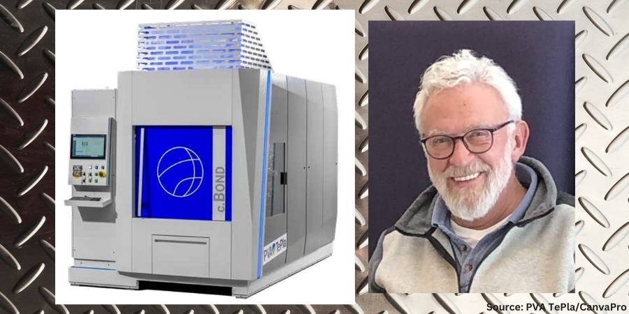
Figure 1. Depiction of a c.BOND machine
In the traditional diffusion bonding process, a vacuum furnace provides radiant heat to the surface of the part. Subsequently, the heat is conducted through the assembly and transmitted to the faying surface (i.e., surfaces in contact at the joint) where required. Aluminum excels at conducting heat, particularly at lower temperatures, making it ideal for applications requiring efficient heat dissipation, such as in electronics and automotive components. However, when radiation is the dominant form of heat transfer, particularly at relatively lower temperatures in vacuum below 1112°F (600°C), aluminum’s thermal conductivity is time consuming.
Aluminum’s high reflectivity poses a challenge in traditional diffusion bonding. It is like trying to heat a mirror with a spotlight — the energy is reflected away instead of being absorbed into the material using the traditional diffusion bonding process.
Diffusion bonding of aluminum requires superior temperature control throughout the process. To prevent overheating of the load, slow heating rates traditionally are applied, leading to long process times.
In addition, aluminum alloys have a narrow processing temperature range for successful bonding. When temperatures fall outside that critical temperature band, a poor bond is produced.
New Diffusion Solution with Conductive Heating
To overcome the existing challenges of bonding aluminum, a global manufacturer of both industrial furnaces and PulsPlasma nitriding systems alongside its partner initiated an extensive development program. The result was an innovative solution: integrating heating elements directly into the press platens. This approach speeds up the bonding process and significantly reduce enhances efficiency by directly transferring heat to the aluminum components.
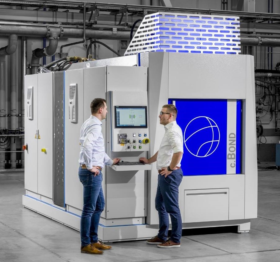
The culmination of this research and development is the c.BOND machine. The machine features a combination of direct conduction heating through the top and bottom platens, which are in contact with the assembly. This design ensures bi-directional homogenous heating and more precise temperature at the bonding interface where it is required.
The machine utilizes a hot-press tool with advanced software and feedback sensors to achieve micrometer-precise pressure control across the entire component surface. This ensures uniform bonding over large areas. Furthermore, the system allows for selective heating of specific areas, preventing unnecessary heat exposure to other parts of the component.
The high-vacuum atmosphere within the chamber eliminates contamination and prevents voids in the bonded joint.
With this machine, the time to heat the part to the ideal temperature for bonding is cut in half compared to traditional radiant heating. With less processing time required, the energy requirements are reduced by up to 30% as well. Multilayer stacking is also possible, which can further increase productivity.
With the size of components continually getting smaller in sectors like semiconductors and electronics, controlling the amount of time, and by extension heat, introduced into the part becomes more critical.
Horst-Gunter Leng
The technology demonstrates significant quality improvement of bonded aluminum components. It improves temperature homogeneity in the load by 70%, enhancing bonding across the entire surface. This method also improves the parallelism of parts by 50%, which enhances the accuracy of geometric dimensions, tolerances and product specifications.
As this new machine is commercially available for high-volume production, heat treaters can leverage this furnace technology alongside another unique feature that is incorporated within the system: proprietary automatic bonding software (ABP).
With the automatic bonding software, after parts can be placed in the furnace and a few parameters (such as the size of the bonding area) input, the software automatically calculates the optimum processing parameters. No specific diffusion bonding knowledge from the operator is required. The recipes can be modified according to the type of material being bonded, the thickness of the material, its surfaces and other factors. During the process, the software continuously monitors the process in real time and adjusts parameters accordingly.
Real-World Applications
A unit was installed at a national research facility in Germany, The Günter Köhler Institute for Joining Technology and Materials Testing (ifw Jena), an independent, non-university industrial research institution that conducts research in diffusion bonding, additive manufacturing, brazing, welding, laser processing, material science and other forms of bonding.
The system is compact, requires minimal maintenance, and enables high-volume production of aluminum components for diverse industries. Its benefits are being realized in aerospace, where it creates lightweight yet strong aircraft components. In the semiconductor industry, it provides a cleaner alternative to brazing, eliminating the risk of solder contamination. There is also growing demand for diffusion-bonded aluminum heat sinks, crucial for cooling high-power silicon carbide (SiC) electronics.
Figure 2. Example of the c.BOND machine
Diffusion bonding also has applications for conformal cooling. The concept is to bond layers of sheet metal that contain machined channel/microchannel structures. When combined, the channels provide a path for heat dissipation. Current applications include power electronics for effective heat management and rapid cooling of molds utilized in injection and blow molding processes.
With the size of components continually getting smaller in sectors like semiconductors and electronics, controlling the amount of time, and by extension heat, introduced into the part becomes more critical.
As the features of the internal channels become more miniaturized, it becomes even more important to control the heating during the diffusion bonding process to avoid any distortion in the part. Shortening the cycle time means introducing less heat into the part. This will facilitate creating parts with conformal cooling channels that have finer and finer features.
As mentioned earlier in this article, diffusion bonding is increasingly valuable for joining dissimilar metals, such as aluminum to steel or titanium. This allows engineers to design components and assemblies with the best properties of each metal. For example, one metal might offer superior corrosion resistance while the other provides greater strength. This “packaging” of dissimilar metals opens up new possibilities in design, particularly for overall weight reduction of design and enhancing performance in challenging environments.
When joining dissimilar surfaces, a liquid-phase diffusion bonding process is utilized, particularly when the bonding interface extends beyond R&D-sized samples. This often involves an interlayer of an alloy that typically melts at the faying surfaces. When the interlayer includes aluminum, the machine can deliver controlled heat to increase the bonding speed.
Conclusion
This new approach to diffusion bonding offers an alternative to the traditional method by circumventing the slow process of radiant heating structural assemblies in a vacuum environment. Although the technology in c.BOND is designed to improve the diffusion bonding of aluminum, it can be modified to the specific needs of the client and customized for the alloy, including copper, an alloy that has many applications in specialized heat exchanger and products used in the microelectronics industry. PVA TePla is exploring options to modify the machine to achieve even higher temperatures above the current maximum of 1472°F (800°C).
As diffusion bonding of aluminum gains importance across industries, contract manufacturers and design engineers must embrace the latest advancements to remain competitive. By adopting fast, energy efficient diffusion bonding technologies for aluminum and other materials, they can unlock higher production volumes, reduce costs, improve or achieve global sustainability targets, and increase profitability.
About the Author:
Horst-Gunter Leng Product Manager PVA TePla
Horst-Gunter Leng is the product manager for PVA TePla, a global manufacturer of industrial furnaces and PulsPlasma nitriding systems.
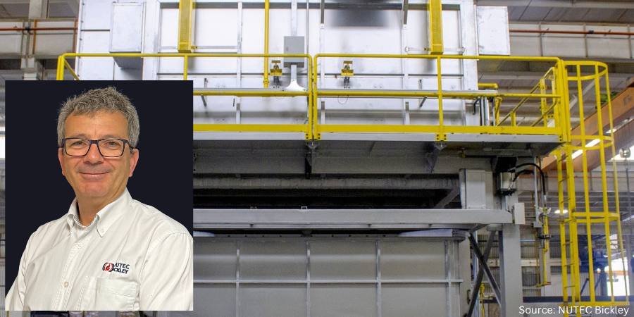
A provider in the power solutions industry has enhanced its operations with a heat treat drop-bottom furnace for the solution heat treatment of aluminum castings. This installation will increase the company’s production capabilities, with the furnace having a load setting of 48 in (123 cm) wide x 36 in (91 cm) high x 141 in (358 cm) long.
The furnace, the fifth designed and manufactured by NUTEC Bickley, has a single temperature control zone, typically operating at 1000°F (573°C), with a maximum of 1075°F (580°C). The load setting will accommodate up to three baskets, equivalent to around 3600 lb (1635 kg) of aluminum parts per cycle. The furnace has been customized to be indirect gas-fired using radiant tube burners. Additionally, the project incorporates a motorized quench tank, rails, movement system, and load/unload platform with elevator device.
Arturo Arechavaleta Vice President, Metal Furnaces NUTEC Bickley
“Efficient and effective solution heat treatment is a vital part of the aluminum casting process,” said Arturo Arechavaleta, vice-president of Metal Furnaces at NUTEC Bickley. “Without the sort of advanced system that we have custom-designed, volume production of high-quality aluminum parts is not feasible. We’re proud to have played an important role in this technology partnership.”
The indirect gas firing is via single centrifugal recirculation that produces a vertical flow pattern. Heating is achieved with four radiant tube burners that have individual flame safety devices. The burner system incorporates a motorized control butterfly valve, and the gas flow is controlled by proportional ratio regulators. This design, with its baffle arrangement, delivers an even flow pattern, providing excellent temperature distribution and control in the furnace’s load chamber and high-efficiency heat recirculation (convection) horizontally across the aluminum castings. Excellent temperature uniformity was always considered an important parameter, and this has been shown to be ±5.4°F (±3°C) under full test in the provider’s manufacturing facility.
In order to maintain excellent thermal efficiency in operation, the furnace walls are fully lined using ultra large proprietary ceramic fiber modules. Their configuration and fixing provide for excellent insulation and long life coupled with low maintenance. The insulation layer is 6 in (150 mm) thick and has a density of 12 lb/ft3 (192 kg/m3).
The installation will see the drop-bottom furnace itself stationary — in a fixed elevated position — with the quench tank and loading car moving to accommodate baskets at the selected position. The furnace has a single, pneumatically operated horizontal slide door. For these particular aluminum castings, the company will employ a motorized water quench system provided by NUTEC Bickley, as well as its rails included leveling and installation. The tank has been designed to accept a full load of pieces within the work basket when the furnace is positioned vertically above it.
Press releases are available in their original form here.