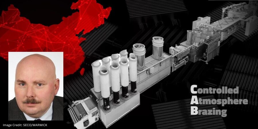
A manufacturer specializing in advanced thermal management solutions has expanded its production capabilities with the delivery of a new continuous controlled atmosphere brazing (CAB) line. The system will support increased output of high-performance cooling components such as heat dissipation plates for data centers and cold plates for electric vehicles, while also serving demand across aviation, photovoltaics, and rail transport.
The company, a Chinese manufacturer focused on temperature control platforms and cooling systems, is investing in the continuous CAB line to strengthen production capacity and support growing demand for compact, high-efficiency thermal management technologies.
The CAB line, supplied by SECO/WARICK — a global thermal processing equipment manufacturer with operations in North America — features a 1,000mm (39.2 in) belt width and is designed to process multiple product types, including 3D vapor chambers and cold plates. The system includes a dry-off oven for part preparation, a radiation brazing furnace operating in a controlled atmosphere, a clean-out chamber to stabilize internal conditions, an air-jacketed cooling chamber, and a final cooling chamber. An integrated control system enables centralized operation and process management across all stages.
Piotr Skarbiński Vice President of Aluminum and CAB Products Segment SECO/WARWICK
“What makes this project unique is the ability to braze two distinct product groups — 3D-VC (3d vapor chambers) and cold plates — on a single line,” said Piotr Skarbiński, vice president of the Aluminum and CAB Products Segment at SECO/WARWICK. Through tailored throughput calculations and a customized cooling configuration, the system is engineered to deliver temperature uniformity and repeatable process control — factors essential to producing high-quality components for modern electronics and power systems, he adds.
As AI servers, EV systems, and advanced electronics generate increasing heat on compact surfaces, reliable aluminum brazing technologies remain essential to delivering performance, durability, and efficiency in next-generation thermal management systems.
Press release is available in its original form here.
Century Aluminum Company has emphasized that next-generation EX smelting technology will be critical to the development of its new primary aluminum smelter, one of the most advanced technologies deployed in the U.S. This platform is designed to improve productivity, reduce energy consumption per ton, and lower emissions, reinforcing both economic competitiveness and environmental performance in primary aluminum manufacturing.
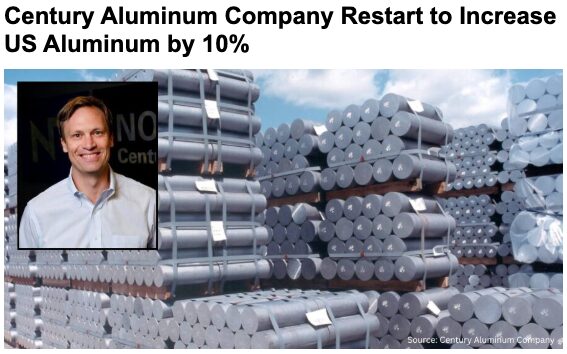
Click on the image above to read more about Century Aluminum’s recent restart to boost U.S. production by 10%.
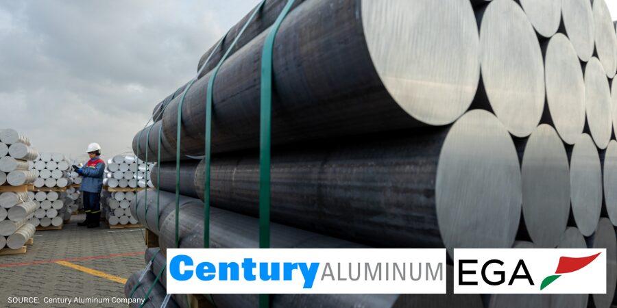
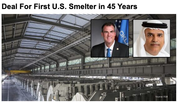
Planned for Inola, Oklahoma, at the Tulsa Port of Inola industrial park, the proposed facility is expected to produce up to 750,000 metric tons of primary aluminum annually, more than doubling current U.S. smelting capacity once fully operational. Century Aluminum will partner with Emirates Global Aluminum (EGA) on the project, with EGA contributing its proprietary EX smelting technology and holding a majority ownership stake, while Century Aluminum provides operational expertise and leadership in the U.S.-based aluminum production. The project aims to strengthen material availability for downstream manufacturers serving automotive, aerospace, energy, and defense markets.
Jesse Gary Chief Executive Officer Century Aluminum Company
“Our partner EGA brings world-class smelting technology and construction expertise that are fast-tracking our collective efforts to realize a new era of domestic primary aluminum production,” said Jesse Gary, chief executive officer of Century Aluminum Company. “This expanded production will benefit critical U.S. industries and create thousands of American manufacturing jobs, reinforcing the vital role of aluminum in national defense and economic vitality.”
EX technology is EGA’s next-generation smelting platform, featuring reduction cells that provide higher productivity per square meter than EGA’s previous DX+ Ultra technology. The cells are larger and have improved current efficiency, enabling greater aluminum production from each smelting cell. The technology supports more cost-effective aluminum production with lower emissions intensity, reinforcing the project’s operational and environmental goals.
For background on the initial announcement of this historic smelter project, click on the image above for our May coverage.
The use of EX technology also positions the project within the broader global landscape of aluminum smelting innovation, strengthening its appeal as an alternative source of advanced smelting capability at a time when governments and manufacturers are increasingly focused on supply chain resilience, domestic capacity, and technology diversification. EGA’s own communications highlight EX as a key step toward large-scale industrialization and a foundation for future growth as a smelting technology provider of choice in the global aluminum industry.
Construction is expected to begin as early as 2026, with commercial production anticipated before the end of the decade. Once completed, the facility is expected to support approximately 1,000 permanent direct jobs and support roughly 4,000 construction roles, while helping reduce reliance on imported aluminum and reinforcing domestic manufacturing capabilities. Industry leaders have described the project as a critical step toward rebuilding U.S. primary aluminum production and supporting long-term supply stability for North American manufacturers.
Press release is available in its original form here.Additional information comes from EGA’s June 2025 press release here.
The increasing adoption of large-scale aluminum die casting, often termed Giga casting, in the automotive industry presents significant challenges in the manufacturing and maintenance of the massive dies required. Learn how heat treatment plays a critical role in ensuring the performance and lifespan of these Giga dies, primarily made from H13 tool steel or its derivatives.
This informative piece was first released inHeat Treat Today’sMay 2025 Sustainable Heat Treat Technologies print edition.
Introduction
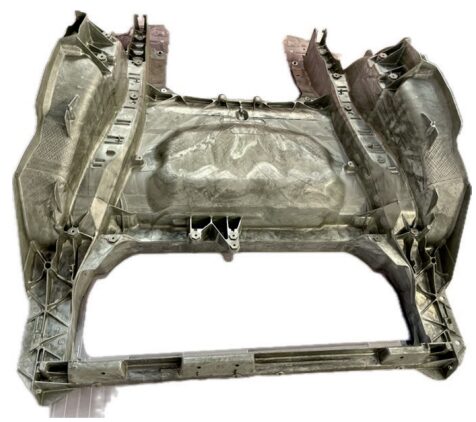
In an article from 2005 on vacuum heat treating of large dies, I concluded, “The use of very large die cast tooling in the automotive industry with part weight over 3 metric tons will increase as aluminum cast parts are increasingly used to lower the manufacturing cost to produce lighter weight automobiles” (Wingens, “H13 Dies.”). Now, 20 years later, a couple hundred “Mega” dies have been heat treated. Six years ago, Tesla decided to take on Giga casting, gaining global attention and taking aluminum die casting to its next level.
Tesla is working on an upgrade to its Giga casting technology to die cast almost all vehicle underbody parts in one piece. They pioneered the use of presses with 6,000 to9,000 tons of clamping pressure to mold the front and rear structures of Model Y during the Giga casting process.
For Tesla, the use of a single component in the rear of the Model Y allowed it to cut related costs by 40%. In the Model 3, Tesla was able to remove 600 robots from assembly by using a single piece from the front and rear of the vehicle (Greco, “Weekly Gigacasting News.”).
Figure 1. Part reduction between Model 3 and Model Y Source: Tesla Q1 2020 Report
They have 14 Giga presses already installed, including two presses with 9,000 tons of clamping pressure for Tesla’s large Cybertruck production at its plant in Austin, Texas, with more to come.
Tesla strategically incorporates inserts in the dies for high-heat zones. These metal elements are specifically placed in areas prone to higher corrosion. Inserts serve a crucial purpose, as they can be replaced individually, mitigating the need to discard an entire costly tool. The dies last hundreds of thousands of shots while individual inserts may only have a lifespan ranging between 30,000 and 80,000 shots (Greco, “Weekly Gigacasting News.”).
Tesla currently employs two sets of dies per machine. While one set is actively mounted on the Giga Press, the other set undergoes routine maintenance. These sets are periodically rotated to ensure continuous and efficient production (Greco, “Weekly Gigacasting News.”).
Figure 2. Tesla Model Y single aluminum die-cast piece Source: Wingens, “H13 Dies”
Ford, Toyota, Volkswagen, Volvo, and most Chinese electric car manufacturers have Giga Presses on order. The first North American Giga casting machine, aside from Tesla’s, will be installed at Linamar in Ontario (Greco, “Weekly Gigacasting News.”). This highlights the transformation occurring within the automotive industry with the increasing demand for lighter vehicles and reduced manufacturing costs, which in turn is driving the adoption of large aluminum structural castings produced through Giga casting (Greco, “Weekly Gigacasting News.”). This revolutionary technique necessitates the use of exceptionally large die-casting dies, often weighing several metric tons.
These Giga dies, typically manufactured from hot-work tool steels, such as H13, are subjected to extreme thermal and mechanical stresses during the high-pressure injection of molten aluminum. Consequently, heat treatment plays a pivotal role in achieving the desired mechanical properties, maximizing die life and minimizing the risks of distortion and cracking. This article delves into the complexities of heat treating Giga dies, highlighting the evolution of techniques, current challenges, and emerging solutions.
Historical Perspective
Figure 3. GM Powertrain 16” cube quench test
The heat treatment of large aluminum die-casting dies has evolved significantly over the last few decades. In the early days of vacuum heat treating for die-casting dies (1980s and 1990s), the primary focus was on minimizing distortion and achieving a clean surface finish. This was often accomplished using slow gas quenching rates (<30°F or 17°C/min), which, while reducing distortion, led to the precipitation of grain boundary carbides and consequently, shorter die life due to reduced impact toughness (Wingens, “H13 Dies.”).
Recognizing the need for improved die performance, the North American Die Casting Association (NADCA), along with leading companies in the die casting industry, issued recommendations for a minimum surface quench speed of 50°F/min (28°C/min). This shift, coupled with the selection of higher quality die materials and the development of heat treatment specifications, such as GM Powertrain DC-9999-1 (1995) and Ford AMTD DC2010 (1999), resulted in significant cost savings and improved die life within the North American automotive industry. These specifications emphasized the importance of both material quality and heat treatment procedures (Wingens und Edenhofer, “Bauweise und Funktion.”).
Challenges in Heat Treating Giga Dies
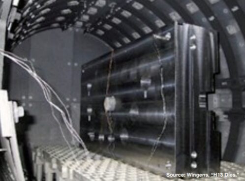
Figure 4. H13 aluminum die casting mold of 5.6 metric tons
Heat treating large H13 aluminum die-casting dies has traditionally balanced the need for sufficient quench rates to achieve robust mechanical properties against the risk of distortion and cracking. As modern automotive and industrial applications demand ever-larger die-cast components, metallurgists and equipment suppliers have focused on several key developments: faster quenching methods in high-pressure vacuum furnaces; process strategies, such as interrupted quenching, to stabilize temperature gradients; and increasingly powerful auxiliary systems capable of handling extremely heavy loads and high thermal loads (Wingens, “H13 Dies.”).
Achieving Adequate Quench Rates to Avoid Grain Boundary Precipitation
H13 (or similar hot-work tool steels) benefits from a sufficiently rapid quench to bypass detrimental grain boundary precipitation, which compromises toughness and die longevity. Many die-casting specifications — including those from NADCA — recommend a minimum quench speed of 50°F/min (28°C/min) measured near the die surface to maintain a uniformly fine microstructure (Wingens, “H13 Dies.”). Without such fast cooling, large dies can exhibit unwanted carbides at prior austenite grain boundaries and reduced impact strength.
For dies weighing several metric tons, however, achieving even 50°F/min (28°C/min) at the die surface is nontrivial. Heat must be extracted swiftly from thick cross-sections, yet the bulk thermal conductivity of H13 places inherent limits on how quickly the die core can be cooled. The result has been widespread adoption of high-pressure gas quenching (HPGQ) in single- or multi-chamber vacuum furnaces, with nitrogen pressures often exceeding 10 or 15 bar (Wingens, Maximizing Quenching and Cooling in Vacuum Heat Treating 2015).
The advent of Giga casting, with its significantly larger dies (weighing > 3 metric tons), introduces a new set of challenges for heat treatment processes. Achieving the required metallurgical properties and minimizing defects in such massive components demands sophisticated techniques and equipment.
Figure 5. Acceptable (left) and unacceptable (right) H11 microstructure (500x)
Key challenges include:
Uniform heating and cooling: Ensuring uniform temperature distribution throughout the large die volume during heating to the austenitizing temperature and subsequent quenching is critical to avoid uneven phase transformations and the development of internal stresses that can lead to distortion or cracking.
Achieving adequate quench rates: Extracting heat swiftly from the thick cross-sections of Giga dies to achieve the recommended quench rate of at least 50°F/min (28°C/min) at the surface thermocouple (Ts), as mandated by NADCA #207, is nontrivial due to the inherent limitations of the thermal conductivity of H13 steel.
Minimizing distortion and cracking: The substantial temperature difference between the surface and the core during rapid quenching increases the risk of both distortion and cracking in these large components.
Applying existing specifications: Current specifications, like NADCA #207, were primarily designed for die inserts estimated at up to 1 ton. The applicability and adequacy of these specifications for Giga dies, which weigh several tons, are being questioned. Issues, such as the number and location of test coupons needed to accurately represent the properties of the entire block, need to be addressed.
Equipment capacity: Heat treating Giga dies necessitates vacuum furnaces with adequate weight and cooling capacity, capable of handling the large dimensions and masses involved.
Modern Heat Treatment Techniques for Giga Dies
Advanced vacuum heat treatment technologies and process strategies have been developed and implemented to address the challenges associated with heat treating Giga dies.
High-Pressure Gas Quenching (HPGQ)
The widespread adoption of HPGQ in single- or multi-chamber vacuum furnaces, with nitrogen pressures often exceeding 10 or 15 bar, is crucial for achieving the necessary rapid cooling rates for large H13 dies. Systems with radial gas nozzle systems and powerful fans (up to 800 kW) ensure effective gas flow through the large load volume (Wingens, “Maximizing.”).
Directional Cooling
Some advanced vacuum furnaces incorporate directional controlled cooling capabilities, allowing for the manipulation of gas flow patterns to promote more uniform heat extraction from complex die geometries, thus minimizing distortion (Wingens, “Maximizing.”).
Interrupted Quenching (Isothermal Hold)
Interrupted quenching techniques are employed to mitigate the risk of distortion and cracking caused by extreme temperature gradients. By pausing the quench at an intermediate temperature (sometimes referred to as a “warm bath” effect), the internal heat of the die has time to diff use outwards, equalizing temperatures and reducing residual stresses before the quenching process resumes (Wingens, “Maximizing.”).
Large Vacuum Furnaces
Furnace manufacturers have developed Giga vacuum furnaces specifically designed to handle the size and weight of these large dies, with load capacities up to 5,000 kg or even 8 tons (Wingens, “H13 Dies.”).
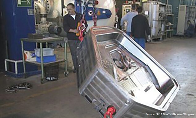
Figure 6. A 6t H13 die, the largest of its time (2004), processed for the German automotive industry
Adherence to NADCA Recommendations
Despite size difference, the fundamental principles of heat treating H13 steel for die casting, as outlined in NADCA #207-2003, remain relevant. Achieving a minimum surface cooling rate of 50°F (28°C) per minute in the critical temperature range is still a key objective. Furnaces with high backfill capabilities (minimum 2 bar for premium, 5 bar for superior quality) are preferred.
Precise Temperature Control
Modern furnaces are equipped with sophisticated digital controls and multiple thermocouples to monitor and adjust temperature profiles in real time, ensuring uniform heating to the austenitizing temperature — typically around 1885°F (1030°C) for H13 — and precise control during the quenching and tempering stages.
Following the rapid quench, a minimum of two tempering cycles is required, with cooling to ambient temperature between each cycle. A final stress temper is often performed to relieve residual stresses.
Impact of Material Science
While the heat treatment process is critical, the selection of high-quality die steel is equally important. Typically, Giga dies are made from premium or superior grade H13 steel, which, according to NADCA #207-2003, should meet stringent requirements for cleanliness, micro-banding, and impact toughness.
Ongoing research also explores the use of improved die steels like Dievar and QRO-90, which exhibit enhanced thermal fatigue resistance. Proper heat treatment is essential to unlock the full potential of these advanced alloys.
Future Trends and Outlook
The field of heat treating Giga dies is continuously evolving to meet the increasing demands of the automotive industry. Future trends and considerations include:
Revision of specifications: The NADCA organization recognizes that the current NADCA #207 specification may need to be revisited to better address the unique challenges posed by Giga dies in terms of testing, quality assurance, and acceptable property variations across the large die volume.
Advanced process control: The increasing use of heat treatment simulation and finite element method (FEM) analysis allows for the prediction and optimization of hardening processes, including the estimation and compensation of thermal gradients.
Innovative heat treatment processes: Emerging techniques like long martempering, which offer a balance of high hardness and toughness in less time, are being explored as potential alternatives to traditional quenching and tempering for hot-work tool steels (Duarte, “Improving Hardening.”).
Energy efficiency: Efforts to reduce the energy consumption associated with HPGQ are ongoing, focusing on optimizing furnace design and control systems.
Integration with Industry 4.0/5.0: Digitalization and automation are expected to drive advancements in heat treatment processes, leading to improved efficiency, higher quality, and simplified task execution.
Figure 8. Loading of 5t H13 into a 15 bar Ipsen SuperTurbo Treater
Conclusion
The efficient and effective heat treatment of Giga dies is paramount to the success of large-scale aluminum die casting in the automotive industry. While the fundamental principles of heat treating H13 steel remain relevant, the sheer size and weight of these dies necessitate the use of advanced vacuum furnace technologies, including HPGQ, directional cooling, and interrupted quenching strategies. Adherence to industry recommendations, such as the minimum quench rates specified by NADCA, is crucial for achieving the desired metallurgical properties and maximizing die lifespan. As the Giga casting market continues to expand, ongoing research and development in heat treatment processes, equipment, and specifications will be essential to meet the evolving demands for these critical manufacturing tools.
References
Chrysler Corporation, Hot Work Tool Steel Manufacturing Standard, Auburn Hills, MI, 1983.
Duarte, Paulo. “Improving Hardening and Introducing Innovation for In-House Heat Treat.” Heat Treat Today, March 2025, https://www.heattreattoday.com/improving-hardening-and-introducing-innovation-for-in-house-heat-treat.
Greco, Luca. “Weekly Gigacasting News.” 2024.
Wingens, Thomas and Bernd Edenhofer. “Bauweise und Funktion eines neuartigen Großkammer-Vakuumofens zum Härten von Schweren Formen und Gesenken.” 60thHeat Treat Colloquium (2005).
Wingens, Thomas. “Maximizing Quenching and Cooling in Vacuum Heat Treating.” 28th ASM Heat Treating Society Conference (2015).
Wingens, Thomas. “Vacuum Furnace Hardening of Very Large H13 Dies.” Industrial Heating, January 2005.
About The Author:
Thomas Wingens Founder & President Wingens Consultants
Thomas Wingens, founder and president of WINGENS CONSULTANTS, boasts over 35 years of experience in the heat treat industry, more than 15 of which are in strategic and executive positions. With his masters in Material Science and Business Administration as well as having served as a heat treater and metallurgist, Thomas holds a unique combination of academic knowledge and industry skills. He has worked in executive positions at Ipsen, Bodycote, SECO/WARWICK, and Tenova. Thomas has also contributed his knowledge and experience as a co-presenter with Doug Glenn at Heat Treat Boot Camp for the last five years.
For more information: Contact Thomas Wingens at wingens@gmail.com.
The advent and increasing adoption of electric vehicles (EVs) has brought a wave of change to the automotive supply chain, including the heat treating industry. While the internal combustion engine (ICE) and all its related components may one day become a thing of the past, there are several key areas of every vehicle that aren’t going anywhere fast. In this Technical Tuesday article, Rob Simons, metallurgical engineering manager at Paulo, discusses the difference between EV and ICE vehicles and the latest heat treating trends to be aware of.
This informative piece was first released in Heat Treat Today’s August 2024 Automotive print edition.
ICE vs. EV Technology
The most apparent difference between EVs and ICE vehicles is that, with EVs, fuel and internal combustion engines are no longer needed. The two vehicle types rely on different sets of key components, and when it comes to making the cars run, EVs use fewer parts that require heat treatment.
Table 1. Existing ICE technology vs. EV technology
Without ICE systems, EVs require fewer fasteners, shafts, gears, and rods — all parts that are typically heat treated. But that doesn’t mean heat treatment is less critical for EVs. In fact, certain parts require additional attention on EVs when compared to ICE vehicles, and many safety-critical parts remain the same across both categories. Let’s begin our discussion with the differences in braking systems between the two technologies and what that means for heat treatment.
Latest Trends in Disc Brake Rotors
How EV Brake Systems Work
There’s no question that electric power innovations have completely revolutionized the way vehicles (and the automotive industry) operate. The regenerative braking system is just one aspect of this. Instead of relying on the conventional hydraulic system every time you press the brakes (which uses friction to decelerate), manufacturers have found a way to use the vehicle’s kinetic energy to put the electric motor into reverse, slowing down the vehicle and returning energy to the battery.
Although regenerative braking is more efficient, hydraulic braking still has one key advantage: stopping power. EVs today are equipped with conventional braking mechanisms for emergency purposes.
The Rust Conundrum
To address recurring rotor corrosion, heat treaters introduced ferritic nitrocarburizing (FNC). FNC is a thermal process traditionally used for case hardening, and for brake rotors, it’s used to achieve corrosion resistance.
The Solution: Corrosion-Resistant Rotors with FNC
To address recurring rotor corrosion, heat treaters introduced ferritic nitrocarburizing (FNC). FNC is a thermal process traditionally used for case hardening, and for brake rotors, it’s used to achieve corrosion resistance.
Figure 1 shows a perfect example of the difference that FNC makes. These are pictures of brake rotors from electric vehicles owned by two Paulo team members — one has brake rotors that were ferritic nitrocarburized and show no signs of rust, whereas the other did not go through the FNC process.
Figure 1a. EV brake rotor without FNC
Source: PauloFigure 1b. EV brake with FNC
Source: Paulo
Ferritic Nitrocarbonizing Process
FNC is a case hardening technique that uses heat, nitrogen, and carbon to toughen up the exterior of a steel part, improving its durability, decreasing the potential for corrosion, and enhancing its appearance. FNC is unique in that it offers case hardening without the need to heat metal parts into a phase change (it’s done between 975–1125°F). Within that temperature range, nitrogen atoms can diffuse into the steel, but the risk of distortion is decreased. Due to their shape and size, carbon atoms cannot diffuse into the part in this low-temperature process. However, carbon is necessary in the FNC process to generate desirable properties in the intermetallic layer.
Heat Treated Materials for Automotive Seating Components
Safety-Critical Components
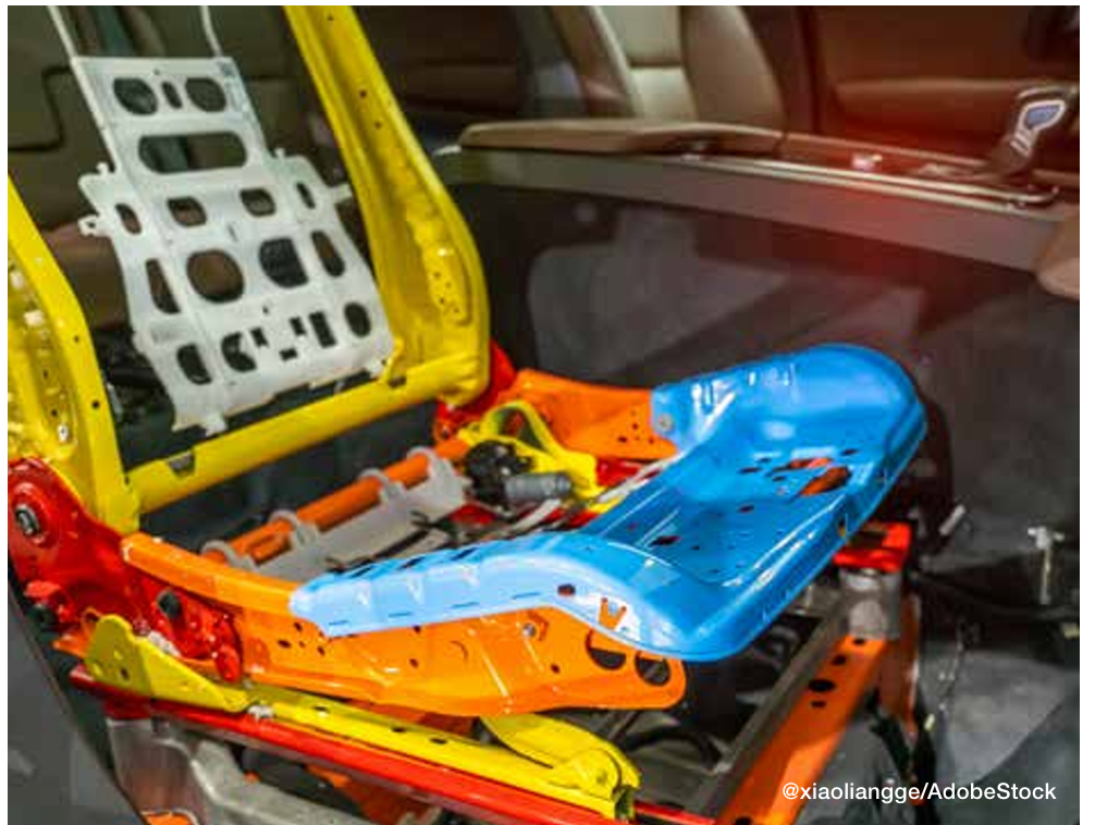
Like brake rotors, many automotive seating components (like mechanisms for seat recliners) are here to stay. Thermal processing is used to achieve stringent specifications that are put in place to keep drivers safe in the event of a collision. EV seat components and the thermal processes used to make them crash-ready are identical to those of ICE vehicle components.
Figure 2. To achieve the stringent specifications for components like seat recliners, identical
thermal processing is implemented for both EVs and ICE vehicles.
Seating Components
Generally, these components are case hardened (either carburized or carbonitrided), typically using one of the following materials:
1010 and 1020 carbon steel: These are plain carbon steel with 0.10% carbon content, fairly good formability, and relatively low strength.
1018 carbon steel: 1018 is a grade that’s often chosen for parts that require greater core hardness and better heat treatment response than 1010 or 1020.
10B21 boron steel: Boron steels are becoming more popular in the automotive industry due to their excellent heat treatment response.
4130 alloy steel and 8620 alloy steel: Alloy steels are more responsive to heat treatment than plain carbon steels, so the thermal processing specifications for parts made from these materials are often adjusted to account for the material’s innate strength properties.
Seat Belt Latches
High-strength seat belt latches are usually made from the following materials:
4140 and 4130 alloy steels: 4140 alloy steel is one of the most common engineering steels used in manufacturing. For seat latches and hooks, 4140 and 4130 will be neutral hardened to increase their strength and hardness throughout due to the high performance and precision required of these parts.
1050 carbon steel: 1050 is a medium carbon steel that contains 0.47–0.55% carbon content. Carbon steels are a less expensive choice when compared to alloy steels such as 4140 or 4130.
Seat Frames and Brackets
Seat frames (also known as seat brackets) give car seats their shape using slender pieces of steel joined together to form the skeleton of the seat. These components are often made from boron steels:
10B21 or 15B24 boron steel: These are a good choice for seat brackets because they are only marginally more expensive than other steels used in seating but have impressive toughness, have a good heat treat response, and are weldable.
A Closer Look: Case Hardening for Seating Components
Case hardening diffuses carbon or carbon and nitrogen into the surface of a metal from the atmosphere within a furnace at high temperatures. Adding carbon or carbon and nitrogen to the surface of steel hardens a metal object’s surface while allowing the metal deeper underneath to remain softer, creating a part that is hard and wear-resistant on the surface while retaining a degree of flexibility with a softer, more ductile core. This softness and ductility create toughness in parts, allowing them to respond to stress without failing. Case hardening is a general term for this heat treating method. Depending on the materials and specifications for the part, we apply various case hardening techniques, including carburizing and carbonitriding.
Figure 3. When it comes to heat treating, innovations are rarely exclusive to EVs.
Carbonitriding
During carbonitriding, parts are heated in a sealed chamber well into the austenitic range — around 1600°F — before nitrogen and carbon are added. Because the part is heated into the austenitic range, a phase change occurs, and carbon and nitrogen atoms can diffuse into the part. Carbonitriding is used to harden surfaces of parts made of relatively inexpensive and easily machined or formed steels, which we often see in automotive metal stampings. This process increases wear resistance, surface hardness, and fatigue strength. It is also good for parts that require retention of hardness at elevated temperatures.
Neutral Hardening
Also called through hardening, neutral hardening is a very old method for hardening steel. It involves heating the metal to a specified temperature and then quenching it, usually in oil, to achieve high hardness/strength. In this process, the primary concern is increasing hardness throughout the part, as opposed to generating specific properties between the surface and the core of the part.
All of the metal components of a seat belt, including seat belt loops, tongues, and buckles, are neutral hardened. Specifications typically dictate that these components are hardened to up to 200 thousand pounds per square inch (ksi).
Because seat belt components are visible to the end consumer, their cosmetics are important in addition to their mechanical properties. It’s important to keep the furnace free of soot and thoroughly clean the parts both before and after heat treatment. Proper cleaning readies the part for secondary processing, ensuring the success of activities like polishing and chrome plating.
The Convergence of EV and ICE Vehicles
To learn more about automotive heat treating, download the free Paulo Heat Treat Guide at paulo.com/AutoGuide.
The EV revolution has significantly transformed automotive manufacturing. Despite these changes, EV parts remain remarkably similar to those of their internal combustion engine (ICE) counterparts. Consequently, any advancements in materials or heat treating processes are swiftly adopted across the entire automotive sector. When it comes to heat treating, innovations are rarely exclusive to EVs.
About the Author:
Rob Simons Metallurgical Engineering Manager Paulo
Rob provides internal and external customer support on process design, material behavior, job development, reduction of variation, and physical analyses at Paulo. He holds a Bachelor of Science in Metallurgical Engineering from the Missouri University of Science & Technology (formerly known as the University of Mines and Metallurgy) and has worked at Paulo since 1987. Rob has analyzed several million hardness data points and/or process behaviors, leading him to develop many process innovations in the metallurgical field.
Heat TreatToday publishes eight print magazines a year, and included in each is a letter from the publisher, Doug Glenn. This letter first appeared in August 2024 Automotive Heat Treat print edition.
In a thought-provoking RealClear Energy(“The Many Problems With Batteries” at RealClearEnergy.org) post on May 30, by Iddo K. Wernick, Ph.D., senior research associate at The Rockefeller University’s Program for the Human Environment and 2013 and 2014 candidate for the Nobel Prize in Literature, Dr. Wernick raises some challenging questions about the belief that battery technology will develop quickly enough, if at all, to achieve net zero by 2050. The complete elimination of combustion, including internal combustion engine (ICE) vehicles, is, in fact, the stated goal of the U.S. Department of Energy — see the Letter from the Publisher in the Heat Treat Today May 2024 Sustainability print issue.
In this issue of Heat Treat Today, we’re talking about heat treatments that are common for the automotive industry, an industry abuzz with talk of EVs and, by necessity, the use of EV batteries. Some of the basic facts and questions raised by Dr. Wernick bear repeating here.
“Batteries provide the essential lynchpin in plans to reduce global carbon dioxide emissions . . . . The dramatic global expansion of in-battery energy storage over the coming decades is deemed necessary to facilitate the growth of wind and solar power and electrified transportation.” In other words, if batteries don’t advance significantly, net zero by 2050 is not going to happen.
Dr. Wernick next points out that “batteries store energy less efficiently than hydrocarbon fuels and release that energy far more slowly than fuels do during combustion.” In fact, the energy density of relatively seldom-used and less efficient “biomass fuels like straw and animal dung is twenty times greater than . . . today’s best lithium-ion batteries, and gasoline has an energy density over 50 times greater.” In other words, with all the technical advances in battery storage over the past decades, batteries are still 50 times less effective and efficient than ICE vehicles.
And while energy densities are substantially lower than carbon-based combustion fuels, a more serious obstacle will be mining (yes, energy-intense, pollution-creating mining) enough minerals to produce these batteries. According to a report issued by the Internation Energy Agency, “supplying the many critical minerals necessary for [the] enormous increases in battery manufacturing” will require “a projected five to 30 times increase in demand for the different battery metals by 2050.” Given the green movement’s propensity to shun any type of mining anywhere, it would appear that battery manufacturers are in the same situation that Moses was in when the Egyptians demanded more bricks but didn’t provide more straw.
China’s dominance in critical battery minerals and battery manufacturing is also mentioned as problematic.
He also covers the inherent bulkiness of batteries: “The inherent bulkiness of battery energy storage quickly shows itself in real world applications. Using current technologies, half of the power produced by the battery pack of an electric vehicle goes to moving the batteries themselves, a basic problem for a mobile power source.” (My emphasis added.)
Some reasonable solutions are offered by Dr. Wernick such as, “incremental changes to the energy system that might reduce emissions more effectively and have greater potential for implementation. Consider the fact that increasing power production from natural gas and nuclear energy could reduce carbon emissions more effectively than building and maintaining the elaborate physical infrastructure necessary for solar and wind and batteries. Or the fact that hybrid electric vehicles require much smaller battery packs, leverage consumer familiarity, and may offer more promise for reducing aggregate vehicular emissions than do fully electric vehicles in the long run.”
Doug Glenn Pubisher Heat Treat Today
Our current world leaders and influencers appear to be somewhat unrealistic and myopic on net zero by 2050. They seem to be ignorant that technologies and materials development are both slow moving and market-driven beasts which cannot be rushed. I don’t know too many people who are opposed to EVs simply because they are electric, but I do know oodles of thinking people who understand that making a quantum leap from ICE vehicles to EVs is something best “driven” (pardon the pun) by the market, and that it takes time.
Three elements in the T6 aluminum heat treatment process — high temperature solution heat treatment, drastic temperature change in the water quench, and a long age hardening process — challenge accurate temperature monitoring. Thru-process technology gives in-house heat treaters the power to control these variables to overcome the unknowns. In the following Technical Tuesday article, Dr. Steve Offley, “Dr. O”, product marketing manager at PhoenixTM, examines the path forward through the challenges of aluminum heat treating.
This informative piece was first released in Heat Treat Today’s August 2024 Automotive print edition.
Aluminum Processing Growth
In today’s automotive and general manufacturing markets, aluminum is increasingly becoming the material of choice, being lighter, safer, and more sustainable. Manufacturers looking to replace existing materials with aluminum are needing new methodology to prove that thermal processing of aluminum parts and products is done to specification, efficiently and economically.
To add strength to pure aluminum, alloys are developed by the addition of elements dissolved into solid solutions employing the T6 heat treatment process (Figure 1). The alloy atoms create obstacles to dislocate movement of aluminum atoms through the aluminum matrix. This gives more structural integrity and strength.
FIgure 1. Critical temperature phase transitions of the T6 aluminum heat treatment process Source: PhoenixTM
Process temperature control and uniformity is critical to the success of T6 heat treat to maximize the solubility of hardening solutes such as copper, magnesium, silicon, and zinc without exceeding the eutectic melting temperature. With a temperature difference of typically 9–15°F, knowing the accurate temperature of the product is essential. Control of the later quench process (Figure 1, Phase 3) is also critical not only to facilitate the alloy element precipitation phase but also to prevent unwanted part distortion/warping and risk of quench cracking.
T6 Process Monitoring Challenges
The T6 solution reheat process comes with many technical challenges where temperature profiling is concerned. The need to monitor all three of the equally important phases — solution treatment, quench, and the age hardening process — makes the trailing thermocouple methodology impossible.
Figure 2. Thru-process temperature monitoring of the three T6 heat treatment phases Source: PhoenixTM
Even when considering applying thru-process temperature profiling technology, sending the data logger through the process, protected in a thermal barrier (Figure 2), the T6 heat treat process comes with significant challenges. A system will not only need to protect against heat (up to 1020°F) over a long process duration but also withstand the rigors of being plunged into a water quench. Rapid temperature transitions create elevated risk of distortion and warping which need to be addressed to give a reliable and robust monitoring solution.
Certain monitoring systems can provide protection to the data logger at 1022°F for up to 20 hours (Figure 3).
Figure 3. Thru-process temperature profiling system installed in the product cage monitoring the T6 heat treatment (solution treatment, quench, and age hardening) of aluminum engine blocks
Thermal Protection Technology
To meet the challenges of the T6 heat treat process, the conventional thermal barrier design employing microporous insulation is replaced with a water tank design, with thermal protection using an evaporative phase change temperature control principle. Evaporative technology uses boiling water to keep the high temperature data logger (maximum operating temperature of 230°F) at a stable operating temperature of 212°F as the water changes phase from liquid to steam. The advantage of evaporative technology is that a physically smaller barrier is often possible. It is estimated that with a like for like size (volume) and weight, an evaporative barrier will provide in the region of twice the thermal protection of a standard thermal barrier with microporous insulation and heat sink. The level of thermal protection can be adjusted by changing the capacity of the water tank and the volume of water. Increasing the volume of water increases the duration at which the T6 temperature barrier will maintain the data logger temperature of 212°F before it is depleted by evaporation losses.
The TS06 thermal barrier design (Figure 4) incorporates a further level of protection with an outer layer of insulation blanket contained within a structural outer metal cage. The key role of this material is to act as an insulative layer around the water tank to reduce the risk of structural distortion from rapid temperature changes both positive and negative in the T6 process.
Figure 4. TS06 thermal barrier design showing water tank, housing the data logger at its core, installed within structural frame containing the insulation blanket surface layer; water tank shown with traditional compression fitting face plate seal Source: PhoenixTM
Obviously, the evaporative loss rate of water is governed by the water tank geometry. A cube shaped tank will provide the best performance, but this may need to be adapted to meet process height restrictions. A TS06 thermal barrier with dimensions 8.5 x 18.6 x 25.2 inches (H x W x L) offering a water capacity of 3.5 US gallons provides 11 hours of protection at 1022°F. A larger TS06 with approximately twice the capacity 12.2 x 18.6 x 25.2 inches (H x W x L) and 7.7 US gallons gives approximately twice the protection (20 hours at 1022°F).
Innovative IP67 Sealing Design
Passing through the water quench, the data logger needs to be protected from water damage. This is achieved in the system design by combining a fully IP67 sealed data logger case and water tank front face plate through which the thermocouples exit. Traditionally in heat treatment applications, mineral insulated thermocouples are sealed using robust metal compression fittings. Although reliable, the compression seals are difficult to use, requiring long set-up times. The whole uncoiled straight cable length must be passed through the tight fitting which, for the 10 x 13 ft thermocouples, takes some patience. Thermocouples can be used and installed for multiple runs, if undamaged. Unfortunately, as the ferrule in the compression fitting bites into the MI cable, removal of the cable requires the thermocouple to be cut, preventing reuse.
To overcome the frustrations of compression fitting, an alternative innovative thermocouple sealing mechanism has been designed for use on the T6 thermal barrier (Figure 5).
Figure 5. TS06 thermal barrier IP67 bi-directional rubber gasket seal; installation of mineral-insulated (MI) thermocouples and RF antenna aerial
Thermocouples can be slotted easily and quickly, tool free, into a precision cut rubber gasket without any need to uncoil the thermocouple completely. The rubber gasket has a unique bi-directional seal, allowing both sealing of each thermocouple but also sealing of the clamp face plate to the data logger tray, which is then secured to the water tank with a further silicone gasket seal. The new seal design allows thermocouples to be uninstalled and reused, reducing operating costs significantly.
Accurate Process Data considerations
The T6 applications come with a series of monitoring challenges which need to be considered carefully to guarantee the quality of the data obtained. Although the complete process time of the three phases can reach up to 10 hours, it is necessary to use a rapid sample interval (seconds) to provide a sufficient resolution. The data logger is designed to facilitate this with a minimum sample interval of 0.2 seconds over 20 channels and memory size of 3.8 million data points, allowing complete monitoring of the entire process. A sample interval of 0.2 seconds provides sufficient data points on the rapid quench cooling curve. The high resolution allows full analysis and optimization of the quench rate to achieve required metallurgical transitions yet avoid distortion or quench cracking risks.
Employing the phased evaporation thermal barrier design, the high temperature data logger with maximum operating temperature of 230°F will operate safely at 212°F. During the profile run, the data logger internal temperature will increase from ambient temperature to 212°F. To allow the thermocouple to accurately record temperature, the data logger offers a sophisticated cold junction compensation method, correcting the thermocouple read out (hot junction) for anticipated internal data logger temperature changes.
Data logger and thermocouple calibration data covering the complete measurement range (not just a single designated temperature) can be used to create detailed correction factor files. Correction factors are calculated by interpolation between two known calibration points using the linear method as approved by CQI-9 and AMS2750G. This method ensures that all profile data is corrected to the highest possible accuracy.
Addressing Real-Time, Thru-Process Temperature Monitoring Challenges
For a process time as long as the T6, real-time monitoring capability is a significant benefit. The unique two-way RF telemetry system used on the PhoenixTM system helps address the technical challenges of the three separate stages of the process. The RF signal can be transmitted from the data logger through a series of routers linked back to the main coordinator connected to the monitoring PC. The wirelessly connected routers are located at convenient points in the process (solution treatment furnace, quench tank, aging furnace) to capture all live data without any inconvenience of routing communication cables.
A major challenge in the T6 process is the quench step from an RF telemetry perspective. An RF signal cannot escape from water in the quench tank. To overcome this limitation, a “catch up” feature is implemented. Once the system exits the quench and the RF signal is re-established, any previously missing data is retransmitted guaranteeing full process coverage.
Process Quality Assurance and Validation
In the automotive industry, many operations will be working to the CQI-9 special process heat treat system assessment accreditation. As defined by the pyrometry standard, operators need to validate the accuracy and uniformity of the furnace work zone by employing a temperature uniformity survey (TUS).
The thru-process monitoring principle allows for an efficient method by which the TUS can be performed employing a TUS frame to position a defined number of thermocouples over the specific working zone of the furnace (product basket). As defined in the standard with particular reference to application assessment process Table C (aluminum heat treating), the uniformity for both the solution heat treatment and aging furnace needs to be proven to satisfy ±10°F of the threshold temperature during the soak time.
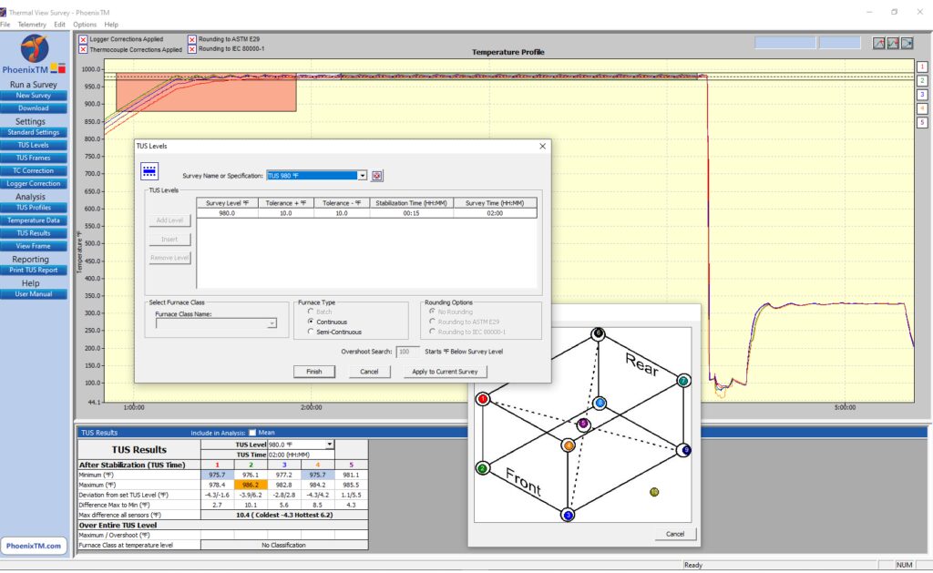
Complementing the TUS system, the Thermal View Survey software provides a means by which the full survey can be set up automatically allowing routine full analysis and reporting to the CQI-9 specification as shown in Figure 6.
Figure 6. View of TUS for T6 aluminum processing in Phase 1 Solution Re-heat Source: PhoenixTM
Interestingly, a significant further benefit of the thru-process principle is that by collecting process data for the whole process, many of the additional requirements of the process Table C can be achieved with reference to the quench. From the profile trace, key criteria such as quench media temperature, quench delay time, and quench cooling curve can be measured and reported with full traceability during the production run.
Summary
To fully understand, control, and optimize the T6 heat treat process, it is essential the entire process is monitored. Thru-process monitoring solutions, designed specifically, allow not only product temperature profiling of all the solution heat treatment, water quench, and age hardening phases, but also comprehensive temperature uniformity surveying to comply with CQI-9.
About the Author:
Dr Steve Offley (“Dr O”), Product Marketing Manager, PhoenixTM
Dr. Steve Offley, “Dr. O,” has been the product marketing manager at PhoenixTM for the last five years after a career of over 25 years in temperature monitoring focusing on the heat treatment, paint, and general manufacturing industries. A key aspect of his role is the product management of the innovative PhoenixTM range of thru-process temperature and optical profiling and TUS monitoring system solutions.
An international manufacturer of electric vehicles (EVs) is adding an advanced retort pit furnace for the production of EV chassis. The equipment’s larger working space will allow for the nitriding of very large die elements needed to produce this automotive equipment.
Maciej Korecki Vice President of Vacuum Business Segment SECO/WARWICK Source: SECO/WARWICK.com
“This is the fourth SECO/WARWICKfurnace for this global manufacturer of electric vehicles. Our product solves the challenge of nitriding dies for the production of large-sized chassis, using a working space with a diameter of 1,600 mm and a height of 2,800 mm. We delivered a similar solution to this partner last year,” said Maciej Korecki, vice-president of the SECO/WARWICK Vacuum Segment.
The equipment provided to the company has a compact design with vacuum purging, electric heating supported by an internal circulation fan, and an external cooling system. The retort and heating system’s special design as well as the gas installation ensures long and reliable operation in industrial conditions. The solution is based on a standard vertical VR retort furnace with an enlarged working space (Ø 1600 mm/63 in and 2800 mm/110.2 in effective height), which will allow the manufacturer to nitride the huge dies used for electric car chassis.
The press release is available in its original form here.
A discussion of laser heat treating begun in Heat Treat Today’s Air & Atmosphere 2024 print edition would not be complete without highlighting key sustainability advantages of this new technology. In this Technical Tuesday installment, guest columnist Aravind Jonnalagada (AJ), CTO and co-founder of Synergy Additive Manufacturing LLC, explores how sustainability and energy-efficiency are driven by precision heat application and minimal to zero distortion. The first part, “Advantages of Laser Heat Treatment: Precision, Consistency, and Cost Savings”, appeared on April 2, 2024, in Heat Treat Today, as well as in Heat Treat Today’s January/February 2024 Air & Atmosphere print edition.
This informative piece was first released inHeat Treat Today’sMay 2024 Sustainability Heat Treat print edition.
Laser heat treating is a transformative process that promises superior performance and sustainable practices. Laser heat treating epitomizes precision in surface heat treatment techniques, targeting localized heating of steel or cast-iron components. Laser radiation raises the surface temperature of the metal in the range of 1652°F to 2552°F (900°C to 1400°C), inducing a transformation from ferritic to austenitic structure on the metal surface. As the laser beam traverses the material, the bulk of the component self-quenches the heated zone. During this process, carbon particles are deposited in the high temperature lattice structure and cannot diffuse outward because of quick cool down resulting in the formation of hard martensite to a case depth up to 0.080” (2 mm), crucial for enhancing material properties.
Sustainability through Energy Efficiency
Contact us with your Reader Feedback!
When considering the energy consumption of a typical laser heat treating operation, it’s essential to acknowledge the continuous advancements in laser technology. Modern laser heat treating systems integrate high-power lasers, water chillers, and motion systems, such as robots or CNC machines. With a typical wall plug efficiency of around 50% for diode lasers, these systems represent a significant improvement in energy utilization compared to conventional methods. The typical energy consumption cost for running a 6 kW laser heat treating system is $20-$30/day. The calculation is based on an 8-hour shift with a duty cycle of 80% calculated at national average electric cost of 15.45 cents/kilowatt-hour.
Self-Quenching Mechanism
Laser heat treating operates on the essential principle of self-quenching, leveraging the bulk mass of the material for rapid cooling. This eliminates the dependence on quenchants required in flame and induction heat treating processes, further reducing environmental impact and operational costs.
Precision and Minimal Distortion
At the heart of laser heat treating lies its sustainable and energy-efficient attributes, driven by two fundamental features: precision heat application and minimal to zero distortion of components post-heat treatment. When compared to the conventional methods such as flame and induction hardening, laser heat treatment offers significantly localized heating. This precision allows for targeted heat treatment within millimeter precision right where the hardness is needed, optimizing energy utilization and operational efficiency. Furthermore, the high-power density of lasers enables hardening with minimal to zero distortion, eliminating or reducing the need for subsequent machining operations like hard milling or grinding.
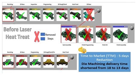
Comparison of the die construction process before and after laser hardening Source: Autodie LLC
A Case Study of Laser Heat Treating in Automotive Stamping Dies
The image above identifies process steps typically involved in construction of automotive stamping dies. During the process of manufacturing automotive stamping dies, the cast dies are first soft milled, intentionally leaving between 0.015” and 0.020” of extra stock material on the milled surfaces. This is done to account for any distortions that will result from the subsequent conventional heat treatment processes such as flame or induction. After heat treating, the dies are then hard milled back to tolerance and assembled.
In the laser heat treating process, by contrast, dies are finish machined to final tolerance in the first step and then laser heat treated without distortion. No secondary hard milling operation is necessary. Typical cost savings for our automotive tool and die customer exceeds over 20% due to elimination of hard milling operation. Total energy reduction is significant, although not computed here. This may result in savings if carbon credits become monetized.
Laser heat treating’s precision, efficiency, and minimal environmental footprint position it as an environmentally friendly option for heat treat operations. As industries continue to prioritize sustainability, laser heat treating may set new standards for excellence and environmental stewardship.
Aravind Jonnalagadda (AJ) is the CTO and co-founder of Synergy Additive Manufacturing LLC. With over 15 years of experience, AJ and Synergy Additive Manufacturing LLC provide high-level laser systems and laser heat treating, specializing in high power laser-based solutions for complex manufacturing challenges related to wear, corrosion, and tool life. Synergy provides laser systems and job shop services for laser heat treating, metal based additive manufacturing, and laser welding.
Global mining and metals specialist Rio Tinto is taking orders for its new aluminum wheel alloy known as Revolution-Al™. Researchers at its Arvida Research and Development Centre in Quebec, Canada, have spent more than five years developing a stronger car wheel alloy that would help cut fuel consumption and improve both safety and handling. The London-based firm says it received its first order for the new Revolution-Al™ alloy in September 2019 and that it designed the alloy to be easy to recycle.
Jerome Fourmann, Technical Director, Rio Tinto
“We wanted to offer automakers a new, innovative alloy that allowed them, through styling and design, to reduce the weight of the wheels, which is very important to improving fuel efficiency – because, in the end, people want to drive not just the safest but also the greenest and most innovative cars,” states Jerome Fourmann, a technical director at Rio Tinto.
According to Rio Tinto, Revolution-Al™ is 15 to 20 percent stronger than the current predominant wheel alloy, A356.2. They claim this translates to a 7 percent weight reduction and improved fuel efficiency or battery range. Additionally, Rio Tinto claims, Revolution-Al™ can be cast in existing facilities and requires less time to produce a wheel, thereby reducing the cost and increasing the rate of production.
The improved alloy features numerous claims; for instance, it is said to be 15 to 20% stronger than the traditional A356.2 alloy, has a seamless transition with existing casting processes, and requires a 2-hour shorter ageing cycle for heat treatment than the A356.2 alloy.
Jean-Francois Laplante, Industrial Product and Investment Director, Rio Tinto
It is worth noting that industrial trials of the new alloy, along with an official OEM test program, featured an optimized automotive wheel design, and Revolution-Al™ passed all OEM trials. What’s more, the alloy can be recycled onto itself, eliminating the need for selling the scrap at a discount.
“The current wheel alloy has been around for a long time and now we’re coming to the market with a new way of doing things,” says Rio Tinto Industrial Product and Investment Director Jean-Francois Laplante. “We were super excited when we saw the result.”
AK Steel, a leading producer of flat-rolled carbon, stainless, and electrical steel products was recently acquired by Cleveland-Cliffs Inc., an iron ore company, with a definitive merger agreement to position the new company to create a vertically integrated producer of value-added iron ore and steel products.
Lourenco Goncalves, chairman of the board, president, and CEO of Cleveland-Cliffs
Under the terms of the merger, Cleveland-Cliffs will acquire all of AK Steel’s common stock, and expand their capabilities across the entire manufacturing process, from mining to pelletizing to the development and production of finished high-value steel products, including next-generation advanced high strength steels for automotive and other industries.
“By combining the best-in-class quality of AK Steel’s assets and its enviable product mix with Cliffs’ debt profile and proven management team, we are creating a premier North American company, self-sufficient in iron ore pellets and geared toward high value-added steel products,” said Lourenco Goncalves, chairman of the board, president, and CEO of Cleveland-Cliffs, who will lead the expanded organization. He added that the new company “is well-positioned to serve both the blast furnace and electric arc furnace segments.”
Roger K. Newport, CEO of AK Steel
“The combination of Cliffs’ iron ore pellet capabilities and our innovative, high-quality steel product development and production is strategically compelling,” said Roger K. Newport, CEO of AK Steel. “Together, we expect to be able to take advantage of growth opportunities faster and more fully than either company could on its own. With AK Steel’s 120-year heritage, which began in Ohio, and expertise in steelmaking, AK Steel and Cliffs make an excellent combination, which we expect will facilitate a smooth integration process.”