Atmosphere/Air Furnace

Why Normalize, and Is a ‘Still Air’ Cool Really Important? Part 2

The Heat Treat Doctor® has returned to offer sage advice to Heat Treat Today readers and to answer your questions about heat treating, brazing, sintering, and other types of thermal treatments as well as questions on metallurgy, equipment, and process-related issues.

This informative piece was first released in Heat Treat Today’s March 2025 Aerospace Heat Treating print edition.


Last time (Air & Atmosphere Heat Treating, February 2025) we addressed the question of why normalizing is necessary. Here we look at the importance of a “still air” cool on the final result. Let’s learn more.

What Is a “Still Air” Cool?

Contact us with your Reader Feedback!

As we learned last month, the term “cooling in air” is associated with normalizing but poorly defined in the literature or in practice, either in terms of cooling rate or microstructural outcome. This lack of specificity has resulted not only in many different interpretations of what is needed, but in a great deal of variability in the final part microstructure.

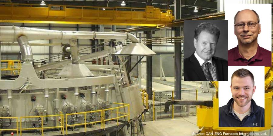
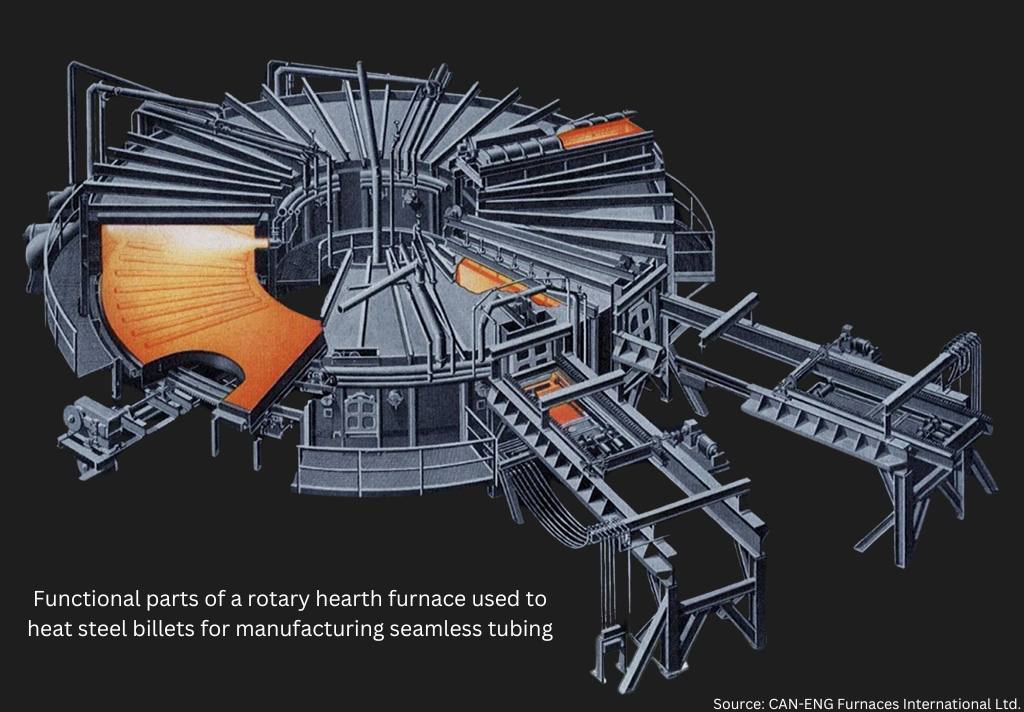
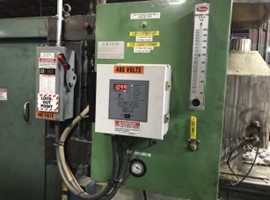
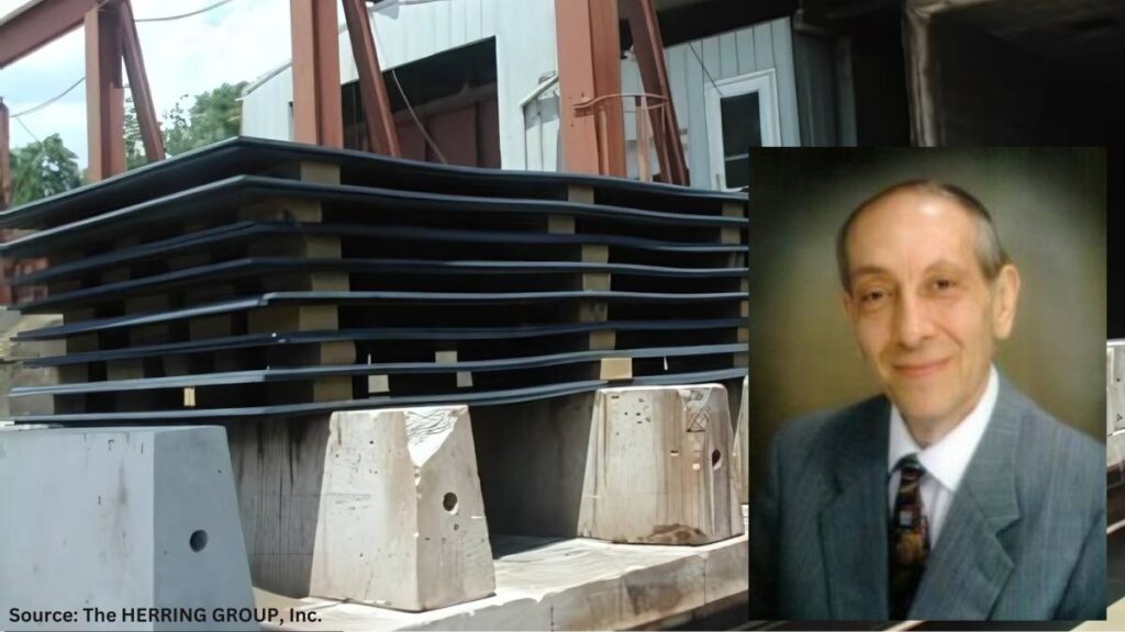
By way of example, this writer has on multiple occasions asked what changes are made to car bottom furnace cycles where cars are pulled outside of the plant for “air cooling” (Figure 1). Questions such as, is the furnace opened and the car pulled out in inclement weather? And, is this practice done on a particularly windy day, or in a rain or snowstorm or when the temperature is below zero? An all-too-common response is, “Only if it isn’t raining ‘too hard’ or snowing ‘too much’; then, we wait a while.” No wonder part microstructures are often found to vary from part to part and load to load!

Most heat treaters agree, however, that normalizing is optimized by a cooling in “still air.” This term also hasn’t been clearly defined, but it will be here based on both an extensive survey of the literature and the most common heat treat practices. In Vacuum Heat Treatment, Volume II, I define a still air cool as: “Cooling at a rate of 40°F (22°C) per minute … to 1100°F (593°C) and then at a rate of 15°F–25°F (8°C–14°C) per minute from 1100°F (593°C) to 300°F (150°C). Any cooling rate can be used below 300°F (150°C).”

Typical car bottom normalizing furnace opening to the outside environment

In addition, many consider nitrogen gas quenching in a vacuum furnace at 1–2 bar pressure to be equivalent to a still air cool. But again, so many factors are involved that only properly positioned workload thermocouples can confirm the above cooling rates are being achieved.

Also, many use the term “air cooling” to differentiate the process from “air quenching,” “controlled cooling,” and “fan cooling.”

Recall from the previous installment of this column that any ambiguity with respect to cooling rate ought to be defined in engineering specifications and/or heat treat instructions so that the desired outcome of the process can be firmly established.

From the literature, several important observations will serve as cautionary reminders. In STEELS, George Krauss points out that: “Air cooling associated with normalizing produces a range of cooling rates depending on section size [and to some extent, load mass]. Heavier sections air cool at much lower cooling rates than do light sections because of the added time required for thermal conductivity to lower temperatures of central portions of the workpiece.”

George Totten’s work in Steel Heat Treatment indicates: “Cooling … usually occurs in air, and the actual cooling rate depends on the mass which is cooled.” He goes on to state:

After metalworking, forgings and rolled products are often given an annealing or normalizing heat treatment to reduce hardness so that the steel may be in the best condition for machining. These processes also reduce residual stress in the steel. Annealing and normalizing are terms used interchangeably, but they do have specific meaning. Both terms imply heating the steel above the transformation range. The difference lies in the cooling method. Annealing requires a slow [furnace] cooling rate, whereas normalized parts are cooled faster in still, room-temperature air. Annealing can be a lengthy process but produces relatively consistent results, where normalizing is much faster (and therefore favored from a cost point of view) but can lead to variable results depending on the position of the part in the batch and the variation of the section thickness in the part that is stress-relieved.

In “The Importance of Normalizing,” this writer offers the following caution: “It is important to remember that the mass of the part or the workload can have a significant influence on the cooling rate and thus on the resulting microstructure.”

Finally, Krauss again observes: “The British Steel Corporation atlas for cooling transformation (Ref. 13.7) establishes directly for many steels the effect of section size on microstructures produced by air cooling.” (Note: Interpretation of continuous cooling transformation (CCT) curves will be the subject of a future “Ask The Heat Treat Doctor” column.)

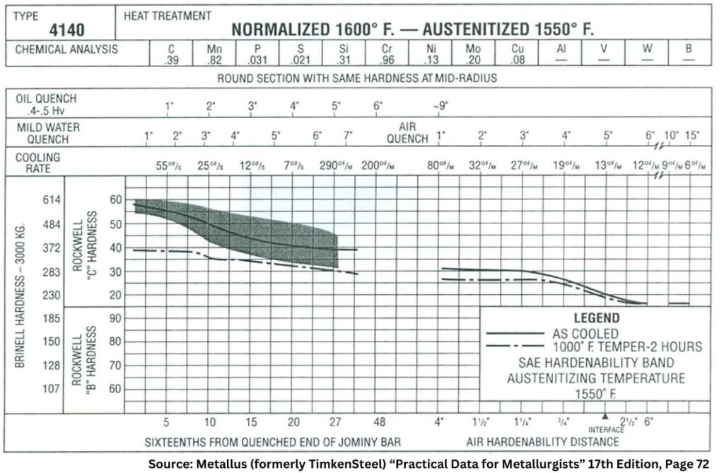
Since hardness is one of the most commonly used criteria to determine if a heat treat process has been successful, it should also be noted that one can usually predict the hardness of a properly normalized part by looking at the J40 value when Jominy data is available.

The Metallus (formerly TimkenSteel) “Practical Data for Metallurgists” provides an example of the type of data available to metallurgists and engineers to help define a required cooling rate for normalizing (Figure 2).

All literature references to normalizing agree (or infer) that the resultant microstructure produced plays a significant role in both the properties developed and their impact on subsequent operations.

Figure 2. Combined hardenability chart for normalized and austenitized SAE 4140 steel showing approximate still air cooling rates and resultant hardness (data based on a thermocouple located in the center of the bar diameter indicated)

Final Thoughts — The State of the Industry

It is all too common within the industry for some companies who wish to have normalizing performed on their products to specify only a hardness range on the engineering drawing or purchase order callout that is given to the heat treater.

Industry normalizing practice here in North America varies considerably from company to company. Normalizing instructions are sometimes, but not often enough, provided on either purchase orders, engineering drawings, or in specifications (industry standards or company-specific documents). These instructions range from, in the case of certain weldments, absolutely nothing (i.e., no hardness, microstructure, or mechanical properties) to referencing industry specifications (e.g., AMS2759/1) or specifying complete metallurgical and mechanical testing including hardness and microstructure.

Most commercial heat treaters often perform normalizing to client or industry specifications provided to them. Others prefer so-called “flow down” instructions in which the process recipe is provided to them. It is a common (and mistaken) belief that this removes the obligation of achieving a given set of mechanical or metallurgical properties even if they are called out by specification, drawing, or purchase order.

Also, the final mechanical properties that result from normalizing are seldom verified by the heat treater. Rather, a hardness value (or range) is reported, but hardness is not a fundamental material property, rather a composite value, one which is influenced by, for example, the yield strength, work hardening, true tensile strength, and modulus of elasticity of the material.

References

ASM International. “ASM Handbook, vol. 4, Heat Treating,” 1991.

ASM International. “ASM Handbook Volume 4A, Steel Heat Treating, Fundamentals and Processes,” 2013.

Chandler, Harry, ed. Heat Treater’s Guide: Practices and Procedures for Irons and Steels. 2nd ed, ASM International, 1995.

Grossman, M. A., and E. C. Bain. Principles of Heat Treatment, 5th ed, ASM International, 1935.

Herring, Daniel H. Atmosphere Heat Treatment, vol. I, BNP Media, 2014.

Herring, Daniel H. Atmosphere Heat Treatment, vol. II, BNP Media, 2015.

Herring, Daniel H. Vacuum Heat Treatment, vol. I, BNP Media, 2012.

Herring, Daniel H. Vacuum Heat Treatment, vol. II, BNP Media, 2016.

Herring, Daniel H. “The Importance of Normalizing,” Industrial Heating April 2008.

Krauss, George. STEELS: Heat Treatment and Processing Principles, ASM International, 1990. 463.

Krauss, George. STEELS: Processing, Structures, and Performance, ASM International, 2005.

Practical Data for Metallurgists, 17th ed. TimkenSteel, 2011

Totten, George E., ed. Steel Heat Treatment Handbook, vol. 2, 2nd ed., CRC Press, 2007.

About the Author

Dan Herring
“The Heat Treat Doctor”
The HERRING GROUP, Inc.

Dan Herring has been in the industry for over 50 years and has gained vast experience in fields that include materials science, engineering, metallurgy, new product research, and many other areas. He is the author of six books and over 700 technical articles.

For more information: Contact Dan at dherring@heat-treat-doctor.com.

For more information about Dan’s books: see his page at the Heat Treat Store.


Find Heat Treating Products And Services When You Search On Heat Treat Buyers Guide.Com


Why Normalize, and Is a ‘Still Air’ Cool Really Important? Part 2 Read More »

Case Study: Adapting a Continuous Rotary Hearth Furnace to an Existing ‘Brownfield’

Are you looking to expand in-house heat treat operations on a brownfield industrial site? These sites can bring complications due to a more restrictive footprint combined with other fixed process conditions. In today’s Technical Tuesday installment, the authors of this case study reveal how to consider available footprint and conveyance mechanism options in a continuous steel reheat furnace, as well as the key design variables for industrial furnaces.

On the research team are the following: Michael K. Klauck, P.Eng., President; Robin D. Young, P.Eng., Vice President — Mechanical Engineering; Gerard Stroeder, P.Eng., Manager — Sr. Technology Specialist; and Jesse Marcil, E.I.E., Project Manager — Mechanical Engineering, all from CAN-ENG Furnaces International.

This informative piece was first released in Heat Treat Today’s February 2025 Air/Atmosphere Furnace Systems print edition.


Introduction

A manufacturer with in-house heat treating had the need to develop a custom furnace for a critical step in the forging process. Specifically, this furnace would be for reheating bottom poured ingots and/or continuously cast round blooms to forging temperatures.

Like all industrial furnaces, the design for such a furnace takes into consideration many factors, including but not limited to:

  • Production throughput/capacity
  • Product configuration/condition
  • Material composition
  • Target product temperature uniformity
  • Soak time
  • Cycle time
  • Serviceability
  • Upstream and downstream process integration
  • Automation

Continuous reheat furnaces that supply steel rolling mills (slabs, blooms) are often designed for very large capacities up to 500 TPH (tons per hour). However, this client’s site was in the 15–30 TPH capacity range. For an open die forging application, this would be considered a low to medium capacity range.

Another consideration was that this was a location with already existing buildings. “Greenfield” sites are undeveloped areas free from prior industrial use; thus, they impose very few restrictions on the layout of the reheating furnace and overall forging cell. In this case, the manufacturer was developing on a “brownfield,” a place with evidence of prior industrial production. Places like these often have the blessing and curse of existing, vacant structures. So, in addition to the design considerations listed above, the physical limitations of a brownfield places constraints on what technology can meet the key performance deliverables.

In this article, we will review how this manufacturer with in-house heat treat was able to customize their furnace to successfully adapt it to the constraints of a brownfield location. The key: An appropriate conveyance mechanism.

Figure 1. Traditional gantry style loader/unloader

Continuous Furnace Design for Cylindrical Round Reheating

The client’s product was a cylindrical “as cast” (continuous casting or static cast) round of approximate weight 1.5–2 tons with required reheating at 2300°F. With a design production capacity of 15–30 TPH, batch reheating was not a viable option; the main choices for continuous furnace reheating are either a walking hearth or rotary hearth furnace (“ring furnace”).

The scope of plant equipment that had to be installed in custom forging cells consists of the following:

  1. Incoming raw material preparation and cutting
  2. Reheat prior to forging
  3. Forging
  4. Post-forging operations — trimming, shearing, and heat treatment (normalizing, tempering)
  5. Machining and finished goods

For a recent reference site, the incoming raw material preparation, the cutting facility consumed approximately 30% of the overall floor space and the forging machine consumed 35% of the footprint, leaving approximately 35% of the available area for the reheating furnace. A comparison of the advantages and disadvantages of the walking hearth technology and rotary hearth technology was made and presented to the end user.

Some of the advantages of the rotary hearth design included the following:

  • A smaller overall footprint/lower consumption of building length
  • Non-water-cooled hearth
  • Positive product positioning with low risk for movement during conveyance
  • No complicated pits/foundations
  • Less complicated drive system
Figure 2. Wrought round bar discharge via a single door system

For this reason, the end user opted for the rotary hearth furnace design over the walking hearth system. A traditional rotary hearth furnace design incorporates two gantry style units, one for loading and one for unloading (see Figure 1). There is a “dead zone” of 10–20° between the charge and discharge which does not contribute to the overall effective heated length.

Alternatively, the CAN-ENG design employs a single door vestibule for both charging and discharging. Instead of dedicated mechanical systems with limited degrees of freedom, this design uses a pedestal-mounted, purpose-built furnace tending robot with a 270° axis slew (see lead article image). The result of these design changes is a more effective utilization of the building width for reheating with no dead zone combined with a robot that has considerable freedom when transferring products from furnace elevation to discharge conveyor elevation.

The robotic feature is particularly important when considering pass line differences for various pieces of equipment in a production cell. Some installations cannot have pits due to high water table considerations, and so the flexibility of robot reach combined with the 270° of axis slew yields fewer restrictions for the end user.

Figure 3. Plan view product layout showing inner and outer charge positions

This rotary hearth furnace can be configured for loading a single long piece or two shorter pieces, one charged towards the furnace inner ring, and one charged to the furnace outer ring, with a suitable gap between the pieces and the refractory walls. This provides considerable flexibility for piece size which is accommodated by the furnace tending robot. Had gantry style loaders/unloaders been used for the charging/discharging functions, the requirement for charging an inner and outer ring of the furnace would have been significantly more challenging.

The overall diameter of a typical steel rotary furnace for 15–30 TPH of production capacity is in the 55’–65’ diameter range (outside of steel service platform). This is dependent on the soak time specified by the end user and the heat up time for the cast or wrought steel
product that is charged.

There are many aspects of industrial furnace design that are not covered in this article, and they would include at a minimum:

  • Refractory — hearth, wall, roof and flue areas
  • Flue design
  • Burner type — heat-up zones (both above and below auto-ignition), holding zones (i.e. soak zones
  • Physical zone separation vs. soft zoning
  • Drive configuration/drive synchronization
  • MES or Level II automation and controls
  • Incoming raw material cutting — carbide-blade, band saw and torch
  • Downstream post-forge heat treatment — normalizing, normalizing & tempering
  • Integrated machining operations
  • Integration with end user’s ERP system

A full article could be dedicated to each of these subjects. Many details are considered confidential design aspects of the furnace builder.

To speak just on support pieces (piers/bunks), nearly all refractory pier compositions are subject to interaction between the scale that is formed during heating (Fe2O3/Fe3O4) and silicates in the refractory matrix, particularly at reheating temperatures of 2300°F or higher.

Under the conditions of pressure and extremely high temperatures, a low melting point liquid compound of fayalite (iron silicates) is formed at the contact point between the workpiece and refractory pier. This is very undesirable and severely limits the overall pier life. Nickel- and cobalt based super alloys have been used successfully at temperatures up to 2450°F, but these materials can be cost prohibitive, especially considering that 70 or more product locations/pier placements may be required. Unless the product requires very restrictive uniformity in reheating (i.e., titanium ingots), consideration of nickel- or cobalt-based work support pieces is not economically feasible.

Figure 4. 3D rendering of a CAN-ENG single door rotary hearth furnace

The most important consideration for the forging cell downstream of the reheating furnace is the uniformity of the bar, ingot, bloom or mult as delivered for forging. Accurate determination of the temperature uniformity is often misleading by infrared radiation (IR) methods since primary scale is removed in the breakdown passes and secondary scale reforms in its place. Workpiece thermocouple measurements at defined locations in predrilled test pieces under full load conditions yield the best results for determining product uniformity prior to furnace discharge.

Conclusion

The modern rotary hearth ring furnace at low to medium production capacities of 15–30 TPH offers a compact footprint that has many advantages compared to water cooled beam walking hearth type reheating furnaces. This is particularly important to brownfield sites which need to adapt the existing industrial layout to current production needs. When combined with automated saw cutting and forging cells, an integrated manufacturing solution results in very low man-hour/ton of labor input. As seen in this article, recent reference sites where material handling conveyors, robots, descale units, vision systems and Level II MES (Manufacturing Execution Systems) were supplied have allowed U.S.-based end users to achieve the lowest total production costs, allowing them to be competitive with India and China.

About the Authors:

Michael K. Klauck, P.Eng., has nearly 40 years of working in the foundry, steel, commercial heat treating and industrial furnace businesses. He started at CAN-ENG in the year 2000 and has been president since 2012.

Robin D. Young, P.Eng., joined CAN-ENG in the year 2000 and has held progressive positions with the company since then. In his current role, he is responsible for departmental oversight of all aspects of Mechanical Furnace Design as well as the Field Service Team.

Gerard Stroeder, P.Eng., joined CAN-ENG METAL TREATING in 1984, a commercial heat treater, moving over to CAN-ENG FURNACES in 1991. With four decades of process and industrial furnace knowledge, Gerard has expert knowledge of industrial furnace costing and ERP business systems.

Jesse Marcil, E.I.E., is a mechanical engineer working on his Professional Engineer Certification (P.Eng.). Prior to joining CAN-ENG in 2021, he worked in the Engineer, Design — Build of Commercial and Industrial buildings. In his four years with the company, he has now completed several large custom ETO (Engineered To Order) furnace projects.

For more information: Contact the team at www.can-eng.com.


Case Study: Adapting a Continuous Rotary Hearth Furnace to an Existing ‘Brownfield’ Read More »

Fueling Efficiency: Retrofit Heat Treat Furnace with Combustible Burner Technology

The automotive industry is going electric — electric vehicles are a popular choice for consumers. To continue sustainable efforts for a healthier planet, heat treaters need to seriously consider energy recovery technologies for their equipment and processes. In this Technical Tuesday article, Harb Nayar, founder, president, and CEO at TAT Technologies, examines the use of combustible burner technology (CBT), specifically CBT technology retrofitted on conveyor furnaces that utilize some level of combustible produced by synthetic or generated atmospheres, and that have peak temperatures above 1400ºF (760ºC).


Annealing, brazing, and even powder metal (PM) sintering, metal injection molding, and additive manufacturing offer the automotive industry components with the precision to meet their demanding standards. For example, the nature of PM manufacturing produces minimal waste, both from a material and an environmental perspective. But most in-house and commercial heat treaters fail to capture and reuse energy or convert emissions with environmentally unfriendly pollutants by use of efficient and available gas-neutralizing equipment. These devices capture and thermally combust hydrocarbons, carbon monoxide, and noxious gases such as ammonia.

Figure 1. CBT unit (model based on LBT-I unit)

The reality is that rather than just neutralize these emissions, heat treaters can use them to heat their parts, even before preheating. The focus of this article is to examine the use of combustible burner technology (CBT) and more specifically, CBT technology retrofitted on conveyor furnaces for processes that has the following:

  • Have peak temperature above 1400ºF (760ºC).
  • Utilize some level of combustible (e.g., H2, CO, and CH4) produced by synthetic atmospheres (e.g., N2-H2) or generated atmospheres (e.g., Exothermic, Endothermic and dissociated ammonia).
Here’s a 20-second video of “dancing” flames exiting a conveyor furnace that is sintering PM parts in a N2-H2 atmosphere at 2050°F (1,000+ lb./hr.). Source: TAT Technologies

Recovering Latent Heat Energy

A typical conveyor furnace found on the shop floor has three distinct zones, a preheat zone, a high heat zone, and a cooling zone. Since it is desirable in these units to have a forward atmosphere flow (toward the entrance end of the furnace and opposite the direction of part travel), combustibles emitted while processing the parts exit at the entrance and are typically burned off before entering the room or exhaust system. Often, flames can be seen burning at the front of the furnace. 

Combustible burner technology, aka lubricant burner technology (LBT), is a thermal technology that was originally developed to address issues in the PM industry (Figure 2). This technology can be supplied with or retrofitted on the front of a conveyor furnace to recover latent combustion energy from combustibles (e.g., H2, CO, CH4) or hydrocarbon vapors (e.g., wax lubricants used for PM parts). The energy can be reused to heat parts before entering the preheat zone. This means that the preheat zone itself can be significantly shortened.  

Retrofit Example — PM Sintering Furnace

PM processing is very specific and often more difficult to adopt compared to other continuous atmosphere furnaces. Given the large percentage of PM parts used by the automotive industry, it offers a good example of how heat treaters can achieve energy and cost savings via energy recovery technology.

A Close Look at the Process

Sintering is commonly performed in continuous atmosphere furnaces. In the sintering process, powder metal is combined with a binder, often solid wax (Acrawax®) or stearate-based lubricants are used in the compaction process to make green parts. Delubrication (aka delube, debindering) then takes place in the preheat section of the furnace. There are three phases during PM sintering:

Typical door-to-door time varies between one to five hours, depending upon the material being sintered.

The most common atmosphere used in sintering processes is N2 with 7–20% H2. In other shops, the atmosphere used is Endothermic gas, which has (approximately) 40% H2, 20% CO, with the balance primarily N2 or dissociated ammonia (DA) with a composition of 75% H2 and 25% N2. In some sintering operations, a mixture of DA and N2 is used.

The atmosphere with all the combustibles travels from the high heat section to the preheat section and finally exits from the front of the furnace where the various pollutants are burned off before entering the exhaust system. The total amount of combustibles varies between 10% and 50% depending on the type of atmosphere and material being sintered.

For example, CBT units have been installed for the delubing of tungsten-based alloy parts prior to sintering in high temperature pusher furnaces.

Capturing Latent Energies

During the PM sintering process, users can capture this latent heat to transfer this energy into the green parts prior to the preheat section. The following are approximations of the latent combustion energy available:

  • H2: approximately 0.1 KW per cubic foot of H2 or 0.35 KW per cubic meter of H2
  • CO: approximately 0.12 KW per cubic foot of CO or 0.4 KW per cubic meter of CO
  • Wax lubricant: approximately 5 KW per lb. or 11 KW per kg of lubricant going into the furnace

How CBT Works

The CBT unit retrofits to the flange of the preheat muffle of the sintering furnace. In its reaction chamber, the furnace atmosphere gases enter from the heating sections carrying the various combustibles. These are circulated in the chamber in which preheated air at 1000–1600°F is introduced through vents in the roof of the chamber (Figure 1).

When the furnace atmosphere and air mix, a combustion reaction takes place with flames being produced over the incoming load of parts that are traveling on the belt towards the preheat section. Heat from theses flames helps vaporize the lubricant and any oils present at a high rate. The lubricant vapors flowing out of the parts are instantly and continuously consumed within the CBT chamber before leaving to enter the exhaust system in the front of the furnace. However, the energy released from the burning lubricants and oil vapors remains, adding to the energy from combustion within the CBT chamber. Enough total heat is generated to heat the parts and the belt to temperature above 930ºF (500ºC) before entering the preheat section. This “recovered” heat energy is essentially free as it is generated from the combustibles and lubricant and oils (e.g., H2 for oxide reduction and lubricant for ease of compaction).

Figure 4. Illustration of the energy generated within the CBT reaction chamber. Parts are moving from right to left. Source: TAT Technologies

Another Case Study Illustration

Energy recovery in a CBT reaction chamber from fully combusting H2 coming from the preheat section of the furnace at a flowrate of 400 CFH (11.3 m3/h) and lubricant coming with the green parts at a rate of 7.2 lbs (3.3 kg) per hour is approximately 235,000 Btu/hr (248 MJ/hr) which is equivalent to an energy savings of approximately 70 KWh of electricity.

Additional Heat Treat Applications

Many other heat treating processes benefit from CBT technology. Some examples follow next.

Annealing often utilizes continuous furnaces.

  • The percentage of H2 in the atmosphere is generally much higher — in some cases 100%.
  • Materials and annealing practices vary from plant to plant.
  • Prior to annealing, the material often has surface oxidation and/or some type of coating (e.g., oils, dry lubricants).
  • The goal is to avoid decarburization and produce an acceptable microstructure, which highly depends on the time/temperature cycle.

Brazing is another thermal process that benefits from CBT technology. 

  • Brazing of most automotive parts is done in either in Exothermic or Endothermic gas or N2-H2 or H2-Ar atmospheres.
  • Materials being brazed are typically low carbon steels or stainless steels. In some instances, other special materials are used.
  • The goal is to have clean, oxide, and soot-free joint surfaces just before the filler metal (commonly copper or nickel-based alloys) melts, flows into the gap between the parts by capillary action, and solidifies producing a homogeneous part.

Summary

Figure 5. Photo shows the main body of a CBT unit. Different product models vary in length and flow capacity, but all produce improvements in product throughput up to 25–50%. Source: TAT Technologies

Heat recovery units like CBT are essential for not only neutralizing harmful furnace gases but oils or other types of organic compounds. This technology allows latent heat energy to be utilized, increasing efficiency and saving energy. Benefits include:

  1. Emission control. Using combustion technology, heat treaters are able to convert potentially harmful pollutants from reaching the exhaust system.
  2. Increased productivity. The technology increases throughput up to 50% depending upon the model used since incoming parts are heated prior to entering the preheat section of the furnace.
  3. Energy savings. The power requirements in the preheat section are reduced and throughput increases up to 50% depending upon the model used.
  4. Improved heat transfer. Parts can be heated to a higher temperature in a shorter amount of time for faster removal of organic materials prior to subsequent reduction of metal oxides.
  5. Decreased unit cost. The energy consumption is lowered and overall cost of parts produced in reduced.
  6. Environmental benefits. Ambient temperature in the front-loading area by 10–30°F is lowered since the burn off flames are significantly smaller. Processes being run are less sensitive to air infiltration in the vicinity of the furnaces.

About the Author:

Herb Nayar
President & CEO
TAT Technologies
Source: TAT Technologies


Harb is an inquisitive learner and dynamic entrepreneur who will share his current interests in the powder metal industry, and what he anticipates for the future of the industry, especially where it bisects with heat treating.


For more information: Contact Harb at harb.nayar@tat-tech.com.


Find Heat Treating Products And Services When You Search On Heat Treat Buyers Guide.Com


Fueling Efficiency: Retrofit Heat Treat Furnace with Combustible Burner Technology Read More »

Piston Rings Manufacturer Bolsters Production with 3rd Nitriding System

Asimco Shuanghuan Piston Ring Co., Ltd. has added a third nitriding system to its heat treating operations, enhancing piston ring production capabilities to serve a range of applications, including the automotive, commercial vehicle, construction machinery, and marine sectors. The compact furnace system was installed in line with two identical systems acquired in 2018 and 2021.

Nitrex installed the latest nitriding system in June, 2024, and Asimco began production in July with a goal to increase its annual production capacity of 180 million pieces and over 4,800 different varieties and specifications. Nitrex’s NITREG®-S stainless steel nitriding technology improves wear resistance, corrosion resistance, fatigue strength, surface hardness, and dimensional stability of piston rings, while reducing friction. These improvements result in better sealing, lower oil consumption, and overall enhanced engine efficiency and durability.

Nikola Dzepina
Nitrex Regional Manager – Asia
Source: NITREX

“The addition of the NXK-812 furnace aligns with Asimco Shuanghuan’s objectives to boost production volume and ensure precision and reliability in high-volume manufacturing,” said Tao Liu, sales manager at Nitrex China.

“By incorporating an additional Nitrex system into their operations, Asimco enhances its ability to produce stainless-steel piston rings with superior performance, durability, and reliability. This advanced treatment makes their products exceptionally suited for high-demand engine applications,” said Nikola Dzepina, account executive at Nitrex.

The press release is available in its original form here.


Piston Rings Manufacturer Bolsters Production with 3rd Nitriding System Read More »

blue bg, left image of airplane on airstrip with sunset, right image of automotive engine

Doncaster’s Atmosphere Furnace Purchase To Bolster In-House Heat Treatment Capabilities

An aerospace, industrial gas turbine, and automotive market leader has expanded its heat treatment operations with a recently purchased air atmosphere furnace. Connecticut-based Doncaster Precision Castings will use the new furnace to support annealing, tempering, and heat treatment of steel and castings.

Doncaster Precision Castings previously received a similar model for use in its heavy-duty industrial processes within the aerospace and automotive sectors. The furnace, supplied by L&L Special Furnace, has a maximum temperature of 1850°F (1010°C) and a capacity to handle a typical load weight of 2,000 pounds.


The press release is available in its original form here.

Find Heat Treating Products And Services When You Search On Heat Treat Buyers Guide.Com

Doncaster’s Atmosphere Furnace Purchase To Bolster In-House Heat Treatment Capabilities Read More »

Global Metal Equipment Producer Acquires Two Heat Treatment Furnaces

A global producer of highly engineered metal earth moving, construction, and mining wear equipment recently commissioned two large capacity heat treatment furnaces. As part of this turn-key contract, Can-Eng Furnaces International Ltd. designed and commissioned individual tempering and stress relieving furnaces. Both heat treatment systems were assembled and tested at Can-Eng’s Niagara Falls facility prior to shipment and commissioning at the customer’s facility.

The furnace systems were part of a major expansion by the customer to satisfy increased demand for large steel castings and weldments used as part of their equipment designs. Both furnaces are equipped with high efficiency, natural gas-fired heating and recirculation systems that have demonstrated to exceed the requirements of AMS-2750 temperature uniformity. Both systems integrated the company’s preferred PLC hardware, which was upgraded to include a more flexible safety rated PLC over conventional hardwired safety circuits.

(source: CAN-ENG)

Global Metal Equipment Producer Acquires Two Heat Treatment Furnaces Read More »

Skip to content