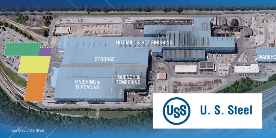
U.S. Steel is investing approximately $475 million in a new quench-and-temper (Q&T) line at its Fairfield Tubular Operations in Alabama, expanding internal heat treating capacity for seamless tubular products. The project centers on the addition of quench-and-tempering processing, a thermal treatment used to enhance the strength and performance of steel tubular products, at a facility that primarily serves oil and gas markets.
Related Reading: Want to learn more about the thermal treatment behind this investment? Click on the image above to explore how tempering improves toughness and balances the hardness achieved through quenching.
“Our new quench and temper line removes a critical production bottleneck, expands capacity, and enables us to meet growing demand,” said Scott Dorn, senior vice president of Tubular Solutions. “The integrated technology also improves traceability from casting through finishing, delivering added value to our [clients].”
Scott Dorn Vice President, Tubular Solutions U.S. Steel
U.S. Steel’s investment in Fairfield is part of broader Tubular expansion plans designed to capitalize on demand growth in key U.S. opportunity basins, such as Permian, Eagle Ford, Haynesville, and Appalachia. These enhancements also help strengthen the Birmingham community, reflecting U.S. Steel’s longstanding commitment to economic contribution in the region and across the state.
The Q&T line is expected to reach full production by Q2 2029.
Press release is available in its original form here.
We’re celebrating getting to the “fringe” of the weekend with a Heat TreatFringe Fridayinstallment: a new specialty alloy development program highlights how manufacturers are accelerating the qualification and scale-up of emerging materials for advanced applications. The initiative combines melting and plasma gas atomization capabilities to help manufacturers develop small-batch alloys for aerospace, defense, medical, energy, and other advanced manufacturing sectors.
While not exactly heat treat, “Fringe Friday” deals with interesting developments in one of our key markets: aerospace, automotive, medical, energy, or general manufacturing.
A new alloy development program aimed at accelerating specialty and small-batch alloy production has been launched, supporting powder metallurgy and advanced manufacturing applications across aerospace, defense, medical, energy, and other industries. The initiative is designed to streamline the transition from alloy design and testing to powder production, helping manufacturers advance qualification and development efforts for emerging materials.
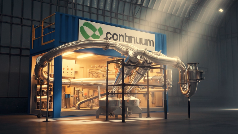
Image Credit: Continuum Powders
Continuum Powders has launched Custom Foundry Runtime (CFR), a program that provides clients with access to specialty and small-batch alloy production using the company’s proprietary melt and atomization platform. The offering is intended to support rapid alloy development, validation, and scale-up for applications requiring custom material compositions.
Jon Cozens CEO Continuum Powders
“Custom Foundry Runtime represents an important evolution for Continuum Powders,” said Jon Cozens, CEO of Continuum Powders. “We’re seeing growing demand for flexible alloy development and securing processing capabilities, particularly for [clients] working with highly specialized or precious materials. CFR gives companies access to advanced atomization infrastructure without forcing them into traditional large-scale production models that don’t fit their needs.”
CFR enables production runs ranging from a few kilograms to larger pilot-scale quantities, allowing clients to evaluate material performance before committing to full-scale manufacturing. The program is designed to support a range of materials, including titanium, nickel-based alloys, precious metals, and other specialty compositions.
The platform combines melting and plasma gas atomization capabilities to produce metal powders for qualification programs, research and development efforts, and advanced manufacturing applications. Continuum states that the program is intended to reduce development timelines while providing a pathway from laboratory-scale alloy creation to production-ready powder supply.
Press release is available in its original form here.
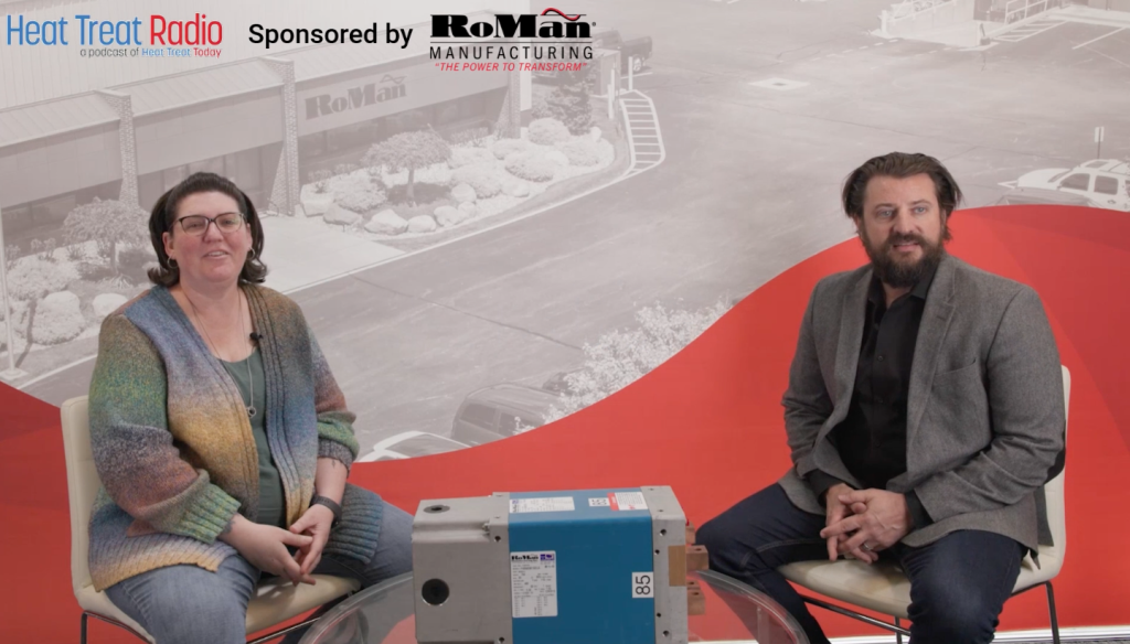
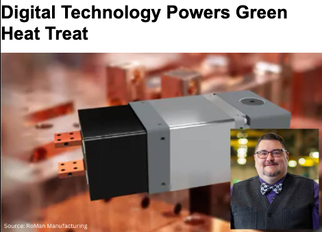
In this episode of Heat TreatRadio, host Heather Falcone sits down with Casey O’Neill, vice president of Sales and Marketing at RoMan Manufacturing, to discuss a holistic approach to energy efficiency in thermal processing. Casey explains how furnace power systems, transformer placement, electrification strategies, and data-driven monitoring can significantly impact operating costs, maintenance requirements, and overall performance.The conversation also explores how emerging technologies such as digital twins and AI-driven analytics may help heat treaters address workforce challenges while improving energy management and productivity.
Below, you can watch the video, listen to the podcast by clicking on the audio play button, or read an edited transcript.
The following transcript has been edited for your reading enjoyment.
Introduction (00:04)
Heather Falcone: Hi, I’m Heather Falcone. Welcome to Heat TreatRadio.
Today we’re talking about holistic solutions to thermal processing system energy efficiency. We’re on-site with the sponsor of today’s episode, RoMan Manufacturing, in Wyoming, Michigan. We had the opportunity to take a tour before recording, so thank you to RoMan for hosting us. Joining me today is Casey O’Neill, vice president of Sales and Marketing. Thanks for joining me today, Casey.
Heat Treat Radio host Heather Falcone (left) sits with the vice president of Sales and Marketing at RoMan Manufacturing, Casey O’Neill (right), on-site at RoMan Manufacturing in Michigan
Casey O’Neill: Thank you for being here. We’re excited to host you and record this on the RoMan campus.
Heather Falcone: You get the whole episode to talk about energy efficiency, but I’d like to start by having you tell us a little about yourself and your background. Since we’re at your facility, you get to do your own introduction and tell us a little about RoMan.
Casey O’Neill: I’m Casey O’Neill, vice president of Sales and Marketing at RoMan Manufacturing. I’ve been with RoMan for a number of years, and where I actually started working at RoMan was selling our products into the furnace market.
This segment of industry is really near and dear to my heart. It’s where I got my start in the business. I’m really excited to be able to discuss all the ways that RoMan Manufacturing specifically works to improve the efficiency of electrically heated furnaces within the heat treating industry and how we can help heat treaters money, while improving operational efficiency.
Heather Falcone: I think there are a lot of misconceptions about what can actually be done with energy efficiency. I’d love to dispel some of those myths and help educate people so that making changes to an energy system does not seem so intimidating.
Casey O’Neill: Absolutely. RoMan has a strong history in a variety of different industries, which allows us to take lessons that we’ve learned from one industry and apply them to other industries where that knowledge may not be understood yet.
That’s what we’ve been working to do within the furnace segment is apply our understanding of power and efficiency and how they relate to each other on different pieces of equipment and introduce those to improve the operations of heat treating companies.
Company History (2:53)
Heather Falcone: That’s really how the company got started, right?
Image Credit: RoMan Manufacturing
Casey O’Neill: Correct. RoMan was founded in 1980 by Dietrich Roth and Robert Hoffman. Dietrich was a brilliant engineer in the power transformation space. His focus was on optimizing power density in a resistance welding transformer.
He developed ways to create the power that was needed in a more compact box. As RoMan has evolved over the last 46 years, we’ve taken that concept and technology and expanded it across the products that we offer different industries.
RoMan supplies products for resistance welding, which is where the company started. We also provide power supplies for glass manufacturing, heat treating furnaces, sintering furnaces, and crystal growing furnaces. Outside of thermal processing, we develop power supplies for specialized projects that require high current. One of RoMan’s strengths is rectifying high-current AC power into high-current DC power.
The expertise needed to do that is fairly limited globally. So, we take on very specialized projects for the government and large primes to put that technology into practice for their applications.
Electrification Trends (4:58)
Casey O’Neill: As it relates to heat treating furnaces, over the last five years, there’s been a significant shift toward electrically heated furnaces. In some cases, companies are looking at converting gas-fired furnaces to electrically heated furnaces. A large part of this trend has to do with broader global electrification initiatives and decarbonization goals. As more and more furnaces are electrified and as more people are looking to buy electrically heated furnaces, our goal is to ensure this industry understands how to optimize that electric power so that the energy is being used by the furnace and not just burning into the air.
Water-Cooled Transformers (6:05)
Heather Falcone: When we talk about energy efficiency and thermal processing, beyond heat loss and leakage, what are the biggest inefficiencies that you’re seeing in heat treat operations today?
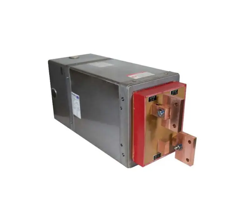
Casey O’Neill: From RoMan’s perspective, our core product is high-current, low-voltage, water-cooled transformers. We also integrate those power devices into power systems, like controls, breakers, PLCs, and communication with the main control system.
Single phase water-cooled transformer | Image Credit: RoMan Manufacturing
One of the key features is water cooling. In a lot of industries, there are applications where having a water-cooled transformer device is going to make the system more optimized than an air-cooled transformer would. While going to an air-cooled transformer may have a lower upfront cost, if you look at the total cost of ownership versus a power supply that integrates RoMan water-cooled device, because of the equipment optimizations, that will save money on energy and maintenance in the long run. RoMan builds our transformers in a way that integrates the water cooling right into the circuit of the transformer, creating a low-profile, high-power density product. The transformers are fully potted and completely sealed off from the elements. Like I said, we used to test our transformers by submerging them in a fish tank and powering them up to show that water could not get into the transformer and short it out. This allows the transformer to not have to be in a box, so it can be mounted on any equipment, because as long as you’re running the cooling water through the transformer, it’s not going to overheat. It’s impervious to any of the outside elements that you would normally put a different type of transformer in a box for. This allows the transformer to be mounted very close to a power feed-through of a furnace.
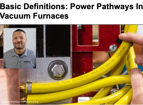
Related Reading: New to furnace power systems? Click on the image above to learn about how electricity travels through a vacuum furnace and why transformer placement matters.
Mounting the transformer in this way has many advantages. The secondary side of a transformer, the output side, is the high-current side of the furnace, and the high-current side of an electric circuit is the drastically more inefficient side of the electric circuit because current is heat.
On the primary side, it’s going to be higher voltage and lower current, but when you’re stepping down the voltage and stepping up the current, which is what you do in a transformer on a resistance-heated furnace, you’re creating a high-current, low-voltage secondary.
Well, high current is high heat. If you’re running high-current through big secondary cables from the transformer to the furnace, every foot of that cable is generating heat and wasting energy. So, you’re paying for energy that’s just going into the air.
Heather Falcone: And you’re heating the whole plant at the same time for nothing.
Casey O’Neill: Exactly. You then either have uncomfortable employees, or you need to get a bigger air conditioner.
What RoMan is working to integrate into this industry is remote mounting of transformers directly next to or close-coupled to the power feed-through of the furnace. By doing that, you’re eliminating the secondary cables altogether.
Not only does that save you energy losses in those cables, but those cables are also water-cooled, so you eliminate having to water-cool the cables. If they are air-cooled, and then they’re kicking heat off into the building. They’re also a large maintenance item and can be difficult to handle.
I’ve been to many different heat treating facilities, and I’ve talked with operators about integrating RoMan transformers where you’re closely coupling them to the power feeders and eliminating the cables. One of the operators joked with me and said he’d be my best friend forever if we could eliminate all those cables because of how difficult they are to do maintenance on. When you have a cable fail, it must be removed and replaced. RoMan is trying to eliminate those cables and mount this transformer right next to the power feed-through, making it more efficient and easier to maintain. We can do this because we’ve created a high-power, low-profile density transformer, that is impervious to elements; it can be outside of a box and mounted right next to the furnace.
Heather Falcone: That makes sense. When you’re looking for a system, you’re looking for something that decreases that, the past of least resistance, right? Faster, quicker, and easier.
Workforce Challenges (12:14)
Heather Falcone: The population of working people is shrinking, and in the next 10 years, it’s going to be the lowest it’s ever been. As such, it’s going to get harder to find and hire maintenance personnel, furnace operators, and electrical technicians. If companies eliminate that problem entirely, it’s a win-win.
Casey O’Neill: Exactly. One of the biggest challenges I see in the near-term future is a massive loss of knowledge base.
Across the heat treating industry, there are incredibly knowledgeable and experienced people that have kept heat treating companies running for the last 50 years that are approaching retirement.
As they leave the workforce, that knowledge base is not easily replaced. It’s quickly becoming one of the major challenges of not just heat treating but every industry.
Adoption of New Furnace Technology (13:30)
Casey O’Neill: At RoMan, our core product is high-current, low-voltage, water-cooled transformers, but we are also integrating some of this core product into broader power systems. As we start to integrate, we are also trying to create enough data feedback. We can monitor current, voltage, resistance values, and other parameters. With digital controls, that data can be extrapolated and fed back into the furnace system.
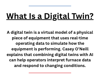
This is where we get into some fun technology. There are companies that can create a digital twin of a piece of equipment by engaging with the equipment and component manufacturers and the OEMs to understand how all of it behaves together.
If we see the transformer temperature internally rising, what does that mean or what could be causing that? If we see a certain part of the furnace inside getting a lot hotter, there are thermocouples inside reading the temperature.
They create a digital twin, and by integrating artificial intelligence, it can start to run simulations in real time, which allows them to communicate next steps with the operator based on what they are seeing with their simulations. So, as experienced personnel enter retirement, we’re going to need to start integrating more of this type of technology into systems or these systems will not operate as well as they should, which means productivity will decrease significantly.
One of the things that RoMan is actively pursuing is determining what feedback our power system can provide to the overall furnace system that’s going to feed into this digital twin and AI simulation to ensure that the furnace can continue to operate in a high productivity fashion, while simultaneously eliminating the challenge of our aging knowledge base.
Related Reading: As furnace systems become more connected, digital controls play an increasingly important role in energy efficiency. Click on the image above to learn about how communication between power systems and furnace controls can reduce energy consumption and support sustainability goals.
Heather Falcone: Right. When you’re undertaking a project like energy efficiency, our tendency might be to focus just on that piece of equipment, and we may miss the opportunity to look at the larger picture and incorporate every piece of equipment.
Casey O’Neill: Exactly. As electrification of heat treating furnaces continues, the operational expense of electricity becomes one of the biggest expenses for heat treat operations. So, managing electric consumption has to become one of the most critical issues to address in order to be profitable.
At RoMan, we don’t just try to sell our products, we try to really engage with the users of our products in every industry that we work in so that they understand from our side how to most efficiently use our products in their system as a way to help the overall OPEX of electricity in a heat treating company, keeping it as minimal as possible or at least as efficient as possible. That way, they are only paying for electricity that is actually used to heat treat products and not paying to kick off energy into the air.
Heather Falcone: Let’s talk a little bit about that whole process that you’ve come up with, because many heat treaters are working with legacy systems. It can seem daunting to go from a VRT to this solution. What do you recommend for how they can attack this issue without being intimidated and rejecting the project entirely?
Casey O’Neill: In a number of industries that we work with, this fear is common. Nobody wants to be first. Everybody wants to be second. If we have new technology, they don’t necessarily want to be the first one to be innovative and integrate it into their system because they also don’t want to be the reason that production goes down if it fails.
So, you have systems with legacy products that have been working for decades and that makes people very comfortable with that system. Even if we can make drastic improvements on the overall operational expense, they are motivated by job security, so they want to work with products and technology they feel comfortable with.
We engage with both small and large captive and commercial heat treaters, and what I found is when you engage with a company that has a group that’s really focused on energy efficiency, especially as electrification grows, those people end up having a lot more say in what technology ends up being integrated into a system.
RoMan has a number of systems integrated into heat treating furnaces, and within our product offerings we have different types of power systems used in various applications. We have air-cooled transformers manufactured at our facility in Grand Haven, Michigan, and we have our high-current, low-voltage water-cooled transformers that are 60 hertz, 480-volt input, very basic, that are integrated into different furnace systems.
Our legacy began in resistance welding in the automotive world. If you’ve ever seen the commercials for vehicle manufacturers where you have the metal frame of a car going down an assembly line with robotic arms moving around, sparks flying — that’s resistance welding. It’s a bad example because when you’re doing the welds, you don’t want sparks, but sparks are good for TV.
That’s a resistance weld. On that robot is a weld gun, and in that weld gun is likely (if it’s in North America) a very small RoMan transformer. The input into that transformer is 1,000 hertz, 620 volts, and it’s coming from an IGBT control. In that industry, in the late ’80s/early ’90s, they started to go from larger stationary spot-welding stations to this robotic welding. They’re putting thousands of amps through that little weld gun, and if they were to use an AC transformer, it would be large, and then they would be running those big heavy cables to the weld gun. Also, robots move around so much, so you end up having a lot of maintenance issues and inefficiencies.
By integrating this IGBT control that can put out 1,000 hertz, you can exponentially shrink the core of the transformer, which makes the transformer size shrink significantly. Now since the ’90s, almost every automotive line is using an IGBT control and a really small, high-current, low-voltage, water-cooled transformer that’s in the weld gun connected to where the weld tips are.
RoMan takes something that’s been used for 40 years in one industry and realized there were many applications that would benefit from integrating this type of technology onto a furnace. When you’re running continuous heat for a long time, you end up creating a lot of inefficiencies, which can get really technical.
This system overcomes many inefficiencies using these different types of technology that all look different from what people are used to seeing. What we are trying to do is educate people on the uses of these new technologies and the benefits of their integration on furnaces, particularly the improvement of operational expenses, electrical efficiencies, and also maintenance.
Furnace Integration — Retrofits (24:24)
Heather Falcone: We have discussed RoMan and the systems. Tell me about integration at the furnace level.
Casey O’Neill: As I have mentioned, we have different furnace applications that use different versions of our technology. For commercial heat treaters, heat treating is how they make money, managing operational expenses of the equipment is absolutely critical to profitability.
We have conducted several trials and product integrations where we’ve worked directly with heat treaters to retrofit equipment so they can start to understand and see the operational gains from using our products.
Related Reading: Casey discusses how power controls affect furnace efficiency and performance. Click on the image above for a deeper look at IGBTs and matching controls to heating loads.
In one case, we had a commercial heat treater that had a vacuum furnace with a large legacy power supply. We have some different data loggers that measure and log power data. We hooked them up to a power logger, and had them operate normally, run different parts that they normally run through that furnace, and we just logged the power data, the kVA, kW, the reactive power, and the power factor — parameters that matter when it comes to power and what the utility companies bill people for. Then we examined that data, and we saw that the power supply that they had for the work that they were doing was oversized.
One of the changes that we could make to optimize the operation of the power supply was to size it more according to their needs. In this case, we retrofitted that furnace with an IGBT control and our small MFDC transformer. We sized the kVA down more to their needs to add some efficiency to the system.
We had them turn it back on and operate normally, using the same parts. We logged the power again and we were able to compare the different runs. We also had them run a burnout run so we could compare the burnouts. As we were doing that, we noticed one run that they were doing after we retrofitted the furnace that wasn’t in any of the logs from before we retrofitted it. We did not know where it came from. The company explained that there is a certain part that they heat treat for a customer and that particular process has a very, very fast ramp rate to get to a very high temperature. In their facility, they only have one furnace that they can do that particular cycle on. After we retrofitted this furnace, they decided to try this particular process, and they were able to do it.
Heather Falcone: That’s awesome.
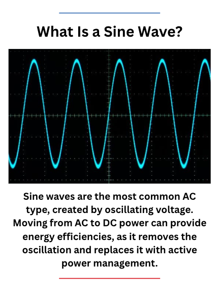
Casey O’Neill: Keep in mind; this was actually a smaller kVA transformer than what was on that furnace before. The output of this transformer is DC, not AC, and AC has a sine wave, which kind of goes like that, and there’s a zero point where it’s always crossing zero. Every time it crosses zero, it’s off for just a little bit. We’re talking milliseconds. But then it has to reheat a little bit. It continues heating, and then it’s off as it crosses zero again.
The MFDC, however, is DC power. DC power is just on, so you’re just managing how much it’s on. As a result, you never have to do that little reheat before you continue heating like you do with AC power.
The best explanation, and this is anecdotal, not data-driven, is when they retrofitted that furnace with DC power, because that DC can just stay on, they were able to ramp much faster and hotter. Even though it was a lower kVA transformer, it still had enough power to get up to temperature. Also, because of the DC power, it was a much better heat, so it could get up to temperature much faster and allow them to do that cycle.
So operationally, they’re now able to run that particular process in two furnaces instead of one. Double the capacity, which is now optimized for a commercial heat treater to be able to shift things around more and have some options when they’re in production.
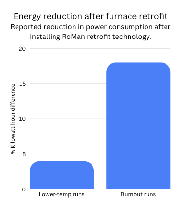
A burnout run is obviously a lot more power than a different run that’s lower temperature or a shorter period of time. On some of those lower temperature runs, there was about a 4% kilowatt hour difference in consumption after we retrofitted it. For the burnout run, the kilowatt hour difference was actually 18%. By retrofitting, it reduced the real power consumption by 18% on every burnout.
The ability to use DC in a resistance application is always going to make it more efficient. But then also by shortening the secondary, you’re eliminating energy waste, optimizing efficiency, and enhancing maintenance.
In that facility, about half of the furnaces now have that IGBT system and these small MFDC transformers. This is a more expensive system. When you look at the total cost of ownership, you have to weigh the costs, is the value there or not? There are certain cases where it is, and there are certain cases where it is not. As I mentioned, half of their furnaces have this system, and the other half do not. That’s because for half of them, there isn’t enough added value to make this change. But for other furnaces at other heat treating companies, we have AC high-current, low-voltage water-cooled transformers like this where those are integrated. We’ve closely mounted them to the power feed-through, and just by getting rid of those secondary cables, we’ve helped improve the efficiency of the furnace. That one is actually really easy to do the math on savings because different size cables have ratings of heat loss per foot. You can easily do the math. On every foot of cable we eliminate; you’re going to save this much in energy consumption.
In some other cases, the transformer, while important, actually becomes less important than the power control. In some commercial heat treaters and in many captive heat treaters, they may run one part over and over and over again. But they have to make sure that every single time it is done exactly the same. We integrate our transformers into a power system where we’re getting controls and other feedback devices that we integrate into the whole system so you can start to monitor and digitally send all that information into a main equipment PLC, which means they can make a lot more informed decisions on how to manage the equipment to ensure that the output is consistent time and time again.
Heather Falcone: Absolutely. I think that’s important to insert in part of the process. As somebody who’s looking to evaluate energy efficiency, you are looking at retrofit, so you need to get the right partner that can give you the education and the foundation to dispel any worries that you might have right up front.
Furnace Integration — New Equipment & OEMs (34:10)
Heather Falcone: But it’s not just retrofits; you can integrate with brand new equipment. Can you talk a little bit about this and working with OEMs.
Casey O’Neill: In general, RoMan has a history of trying to work with everybody in the supply chain, because I think that we offer different forms of value to different companies within that supply chain. The heat treating industry is no different. Furnace users and heat treaters are the ones that are paying their electric bill. They’re the ones that are paying the furnace operators, the maintenance personnel. They’re buying maintenance parts. For them, the value of the RoMan products is going to all be things that impact their P&L.
But we also work with a number of different furnace OEMs where the value is more on them being able to sell a more optimized piece of equipment to an end user. So, in general, most of the furnace OEMs, especially here in North America, are very familiar with RoMan products. They’re going to understandably be very sensitive to their customer needs and the demand. If I have the best product in the entire world, but my customers don’t want it, I am not going to go out of business holding the best product in the world.
As we work with OEMs, they understand how to integrate the RoMan products in various ways to optimize the equipment. At the end of the day though, it’s based on the demand from a heat treating company that will be buying that equipment. Whether they are going to integrate RoMan, add value, be more technologically advanced, or stick with the legacy equipment because that’s what they know.
Again, the education still needs to go back to the heat treating industry, commercial heat treaters and captive heat treaters, to understand the importance of having a highly optimized piece of equipment in their overall system and what it can do for their bottom line.
That’s really how the demand is going to shift. I’m part of RoMan, and so I will always say how they’re going to demand shift to RoMan. But in general, the demand is going to shift from how companies have done it for 50 years and are comfortable with seeing real value in this new technology because it’s going to optimize their system. It’s going to help them manage the system because they are losing a knowledge base. It’s going to give a better output. It’s going to lower their OPEX. As companies become more and more focused on optimization and value, I think you’re going to see a shift to more advanced technology.
However, what I tell everybody is that what RoMan sells is not new technology; it’s 40 years old. It’s just new to this industry.
Biggest Takeaways (37:48)
Heather Falcone: On that subject, what is the big takeaway that you want our readers and listeners to know from everything that we’ve talked about today?
Casey O’Neill: At Roman Manufacturing, our vision is to be the global brand of choice for industrial power conversion solutions, and the heat treating world is a part of that. We never try to just sell a product. Our goal is to work with our customers and the companies that are using our equipment, even if they’re not directly our customer, to make sure that they not only understand the added value, but also can capture the added value, because it’s one thing to know that a product can add value, and it’s another thing to make sure you’re actually capturing it.
At the end of the day, RoMan is focused on our customer and our user base. We will always support our products to make sure that people are squeezing every drop of value out of it that they can. I think that’s how you create really good partnerships when you’re working together to optimize a furnace system, for example. You start to learn from each other to be able to even optimize the equipment that they’re buying in a bigger way.
Heather Falcone: You can learn from each other, continually improve. We can’t do it without working together.
Casey O’Neill: Exactly.
Heather Falcone: Thank you so much, Casey. I really appreciate you spending time with me today.
About the Guest
Casey O’Neill Vice President of Sales and Marketing RoMan Manufacturing
Casey O’Neill is vice president of Sales and Marketing at RoMan Manufacturing, a Grand Rapids, Michigan-based manufacturer of high-current, low-voltage power conversion equipment serving industries including resistance welding, glass, furnace, and other industrial applications.
Casey leads RoMan’s sales, marketing, and market-development efforts with a focus on strategic growth, client partnerships, and expanding RoMan’s presence in global industrial markets. His background includes leadership roles in sales strategy, business development, operations, and manufacturing, giving him a practical understanding of how technical solutions, commercial strategy, and client needs intersect.
For Heat TreatToday, Casey brings a perspective shaped by working closely with industrial clients in demanding thermal-processing, furnace, and power-conversion applications.
Intalus, a U.S.-based manufacturer, is expanding its metal additive manufacturing capabilities through the acquisition of two electron beam powder bed fusion (EB-PBF) systems, a thermal processing technology used to produce high-performance metal components. The investment reflects continued growth in additive manufacturing, where downstream thermal processing is often used to optimize microstructure, density, and performance.
The order includes two eMELT machines from Freemelt, a developer of EB-PBF systems for metal additive manufacturing. Intalus will initially utilize the systems for technology and application development based on Freemelt’s open E-PBF platform, focusing on MedTech applications using titanium as a base material for future serial additive manufacturing. Following this phase, additional applications are expected to be evaluated using other refractory materials, including tungsten. Delivery of the first system is planned for the end of the third quarter of 2026.
Daniel Gidlund CEO Freemelt
“Entering into this agreement with Intalus represents an important milestone as we establish our first industrial presence in the U.S.,” said Daniel Gidlund, CEO of Freemelt.
The collaboration is intended to develop over time, with Intalus holding an option to expand the installation with two additional production machines, supporting a potential transition from development to serial production.
As metal additive manufacturing adoption expands, thermal processing remains an important step in qualifying components for demanding applications. Heat TreatToday has previously reported on the use of hot isostatic pressing (HIP), stress relieving, and other thermal processing methods used to improve the density, microstructure, and performance of additively manufactured metal parts. As noted in Dan Herring and Nikolai Alexander’s article published in Heat Treat Today’sAnnual Aerospace Heat Treating magazine (March 2026), thermal processing and HIP can play a key role in achieving final material properties and reducing internal defects. Readers interested in the relationship between additive manufacturing and thermal processing can explore additional Heat TreatToday coverage in related articles here: AM Drives Hypersonic Engine Development Demand and Can You HIP It? Investigating Hot Isostatic Pressing.
Press release is available in its original form here.
The U.S. Department of Energy’s new Industrial Technology Validation (ITV) program promises a more grounded, results-driven approach to industrial innovation funding that its predecessors. In this Technical Tuesday installment, Michael Mouilleseaux, general manager at Erie Steel, Ltd., examines how the ITV program stacks up against the DOE’s 2021 Industrial Decarbonization Roadmap and whether its structured framework can deliver real results for U.S. manufacturers.
This informative piece was first released inHeat Treat Today’sMay 2026 Sustainable Heat Treat Technologies print edition.
The U.S. Department of Energy (DOE) has introduced a new initiative — the Industrial Technology Validation program — positioning it as a forward‑looking effort to enhance industrial productivity while promoting energy efficiency. This comes on the heels of the DOE’s 2021 Industrial Decarbonization Roadmap, a policy many in the manufacturing sector will remember for its ambitious objectives and disruptive implications. That roadmap targeted five major industrial sectors, said to represent one‑third of national greenhouse‑gas emissions, and extended its reach into areas like heat treating, often relying on what some critics considered misguided science and commercially unproven technology in pursuit of net‑zero carbon emissions by 2050, with a near‑term goal of 50% mitigation by 2035.
Although many hoped these earlier ambitions had cooled, the emergence of this federal validation and funding program raises a familiar question: Is this truly a fresh approach or simply more of the same under a new banner? The DOE states that its latest program aims to enhance U.S. industrial productivity and competitiveness by evaluating emerging or undervalued technologies capable of improving performance, quality, and energy savings (U.S. Department of Energy n.d.).
To its credit, the initiative includes design elements that set it apart from its predecessor. The program requires partnerships between technology developers and industrial host sites, ensuring both the innovation and real‑world application are evaluated in tandem. Developers supply the technology; host sites provide installation environments and operational data. Each project follows a three‑phase structure — planning, installation, and analysis — with performance data reviewed by Lawrence Berkeley National Laboratory and published publicly to promote transparency (ENERGYWERX 2026).
Eligible technologies include pre‑commercial, early‑commercial, and underutilized innovations, with an emphasis on industrial AI, combustion systems, water treatment, and process heating. Funding is available up to $400,000, but critically, it must be cost‑shared 50/50 between the developer and host site — an approach intended to ensure genuine commitment from all parties involved.
The program’s limited application window (September 16, 2025, to January 29, 2026) offers a built‑in evaluation period that could determine whether it deserves extension or broader adoption. Unlike many governmental initiatives, funding is not guaranteed, progress is tied to defined milestones, and the structure appears designed to reduce abuse while fostering pragmatic technological advancement.
Still, the question remains: Does this thoughtful structure ensure success? Not necessarily. It does, however, represent a more grounded, disciplined approach than some previous federal technology‑driven efforts. In a landscape where industrial innovation and regulatory expectation often collide, this program may prove to be a more realistic model, one that acknowledges both the complexity of advanced technology development and the practical realities facing U.S. manufacturers.
Stay tuned. The coming months will reveal whether this model can deliver meaningful progress or simply become another chapter in a long series of well‑intentioned but uneven policy experiments.
U.S. Department of Energy. n.d. “Industrial Technology Validation Program.” Accessed April 3, 2026. https://betterbuildingssolutioncenter.energy.gov/industrial-technology-validation-program.
About The Author:
Michael Mouilleseaux General Manager Erie Steel, Ltd
Michael Mouilleseaux is general manager at Erie Steel, Ltd. He has been at Erie Steel in Toledo, OH since 2006 with previous metallurgical experience at New Process Gear in Syracuse, NY, and as the director of Technology in Marketing at FPM Heat Treating LLC in Elk Grove, IL. Michael attended the stakeholder meetings at the May 2023 symposium hosted by the U.S. DOE’s Office of Energy Efficiency & Renewable Energy.
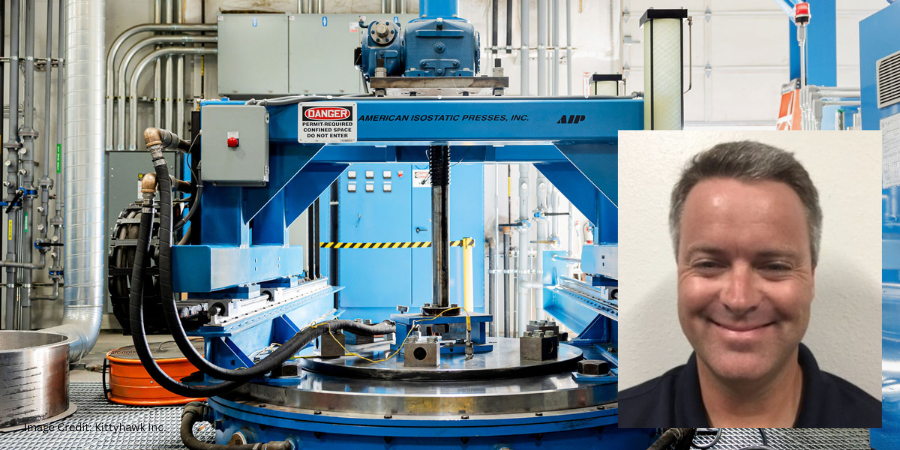
Kittyhawk Inc., a commercial provider of hot isostatic pressing (HIP) services, has placed a purchase order for a new HIP vessel at its facility in Garden Grove, California. The planned investment is intended to expand processing capacity for commercial aerospace, space, defense, and other industries that rely on HIP technology to improve material performance and component integrity.
The new vessel will complement Kittyhawk’s existing HIP operations and support growing client demand across critical manufacturing sectors. The company provides HIP processing services through facilities in California and Oregon.
Brandon Creason CEO Kittyhawk Inc.
“This new vessel is another step in our ongoing investment in long-term growth. As demand continues to increase, we want to make sure our [clients] have access to the HIP services they need when they need them,” said Brandon Creason, CEO of Kittyhawk.
The vessel will measure 46 inches in diameter by 100 inches high. Once operational, the additional system is expected to help reduce production bottlenecks, support faster turnaround times, and meet evolving needs of clients operating in highly regulated and performance-driven markets.
Press release is available in its original form here.
Each year, the 40 Under 40 initiative at Heat Treat Todayrecognizes 40 rising young leaders (ages 40 and younger) in heat treat who are going above and beyond in the industry.
To learn more about what makes someone a quality candidate for this honor, read below to hear from the individuals themselves — alumni of Heat Treat Today’s40 Under 40 — as they share personal updates and industry insights.
Click this link to nominate yourself, or someone you know, by June 26, 2026.
Olivia Ivone Pánuco Valdés
Since being recognized as a 2024 Heat Treat Today40 Under 40 honoree, Olivia Ivone Pánuco Valdés has expanded her role at General Motors from day-to-day metallurgical support into broader process validation, capacity analysis, and manufacturing strategy. Today, as senior process engineer for gears and shafts in metallurgy, she supports heat treatment validation, material quality, and supplier technical reviews for automotive components.
As her responsibilities have grown, so has the importance of collaboration. While technical expertise remains central to her work, Pánuco Valdés says some of her greatest professional growth has come from learning how to influence decisions across teams and organizations. “Technical expertise creates real impact only when it is combined with collaboration and clear communication,” she notes. She has found that even the best technical solutions only deliver results when suppliers, plant personnel, and business stakeholders are aligned behind a common objective. That mindset has also shaped her work as CQI-9 leader in Mexico, where she focuses on distortion control, recipe development, and scrap reduction initiatives.
One project challenge that stands out involved coordinating multiple teams while improving heat treatment processes and addressing quality concerns. Manufacturing decisions, she notes, rarely happen in isolation and often require balancing metallurgical requirements, production realities, supplier capabilities, and business priorities simultaneously. Staying close to the process, relying on data, and maintaining communication with plant teams and suppliers proved critical to moving those efforts forward.
For young professionals considering a career in heat treating, Pánuco encourages staying curious and spending time on the shop floor to understand how materials behave during processing. As the industry becomes increasingly tied to quality, productivity, and sustainability initiatives, she believes future heat treat leaders will need to pair strong metallurgical knowledge with data analysis, continuous improvement, and cross-functional problem-solving skills.
Sergio Gallegos Cantú
Recognized as one of Heat Treat Today’s 40 Under 40 honoree in 2025, Sergio Gallegos Cantú continues to advance heat treat innovation at Quaker Houghton through research, testing, and simulation. As senior metallurgist for the company’s Global Heat Treatment R&D Center of Innovation, he develops and evaluates quenchants while leading metallography and modeling efforts that support heat treatment applications.
The 40 Under 40 recognition brought increased visibility both within Quaker Houghton and across the industry, opening the door to more complex technical projects. “Projects and client needs often present inherent challenges, and I always aim to find a viable and practical solution to achieve the objectives,” Gallegos Cantú says. “These experiences help me grow, enabling us to deliver better solutions.”
One example involved designing a laboratory-scale quenching system capable of replicating a client’s large-scale process. After months of refinement, the team successfully validated the quenchant in the lab, and subsequent production-scale testing closely matched the experimental results — a milestone that demonstrated the value of combining research with practical application.
Gallegos Cantú encourages early-career professionals to embrace curiosity, remain persistence, and view mistakes as learning opportunities. Looking ahead, he expects the next generation of heat treaters to pair traditional metallurgical knowledge with digital tools such as simulation, data management, and artificial intelligence while adapting to emerging manufacturing technologies and energy-transition initiatives.
Eric Roth
Since becoming a Heat Treat Today40 Under 40 Class of 2025 honoree, Eric Roth has stepped into a new position as a metallurgical engineer at a steel and iron foundry, where he focuses on heat treatment quality control and product failure analysis.
The transition has reinforced a lesson he considers essential to long-term success: the importance of strong leadership and effective management. Roth says that understanding how people, processes, and business objectives intersect become increasingly valuable as he takes on greater responsibility for product quality and process performance.
Recently, he faced the challenge of adjusting heat treat cycles to meet tighter Brinell hardness requirements for a client application. The effort required him to deepen his understanding of continuous cooling transformation (CCT) and time-temperature-transformation (TTT) curves while producing a pearlitic microstructure — a notable departure from the tempered martensitic structures he had worked with previously.
One principle continues to guide his approach to the profession: safeguarding quality and protecting the reputation that earns client trust. “Your company’s reputation is priceless,” Roth says. “A few scrapped castings is worth scores more than damage to your reputation, leading to loss of goodwill and eventually of business and revenue.”
As experienced metallurgists and heat treaters retire, he encourages younger professionals to seek out mentorship opportunities and absorb as much knowledge as possible from those who have spent decades in the field.
Heat Treat Today’s 40 Under 40 Authors
Check out some of the technical content that 40 Under 40 alumni have published with Heat Treat Todayover the years:
We’re celebrating getting to the “fringe” of the weekend with a Heat TreatFringe Fridayinstallment: the completion of a strategic investment project at a U.S. vacuum metallurgy facility highlights ongoing efforts to expand plasma gas atomization (PGA) and advanced materials processing capabilities. The project reflects continued investment in the infrastructure behind high-performance manufacturing.
While not exactly heat treat, “Fringe Friday” deals with interesting developments in one of our key markets: aerospace, automotive, medical, energy, or general manufacturing.
A strategic investment in vacuum metallurgy and advanced materials processing capabilities has been completed in the U.S., expanding capacity for plasma gas atomization and manufacturing operations serving aerospace, defense, energy, medical, and specialty materials sectors.
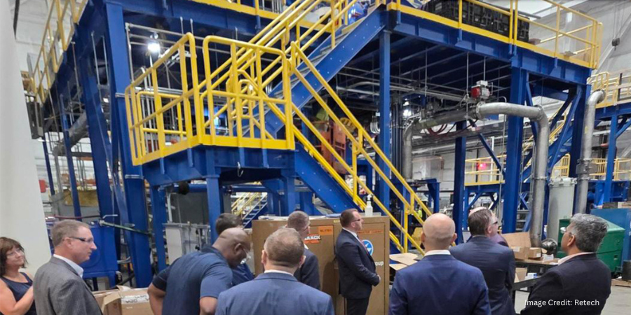
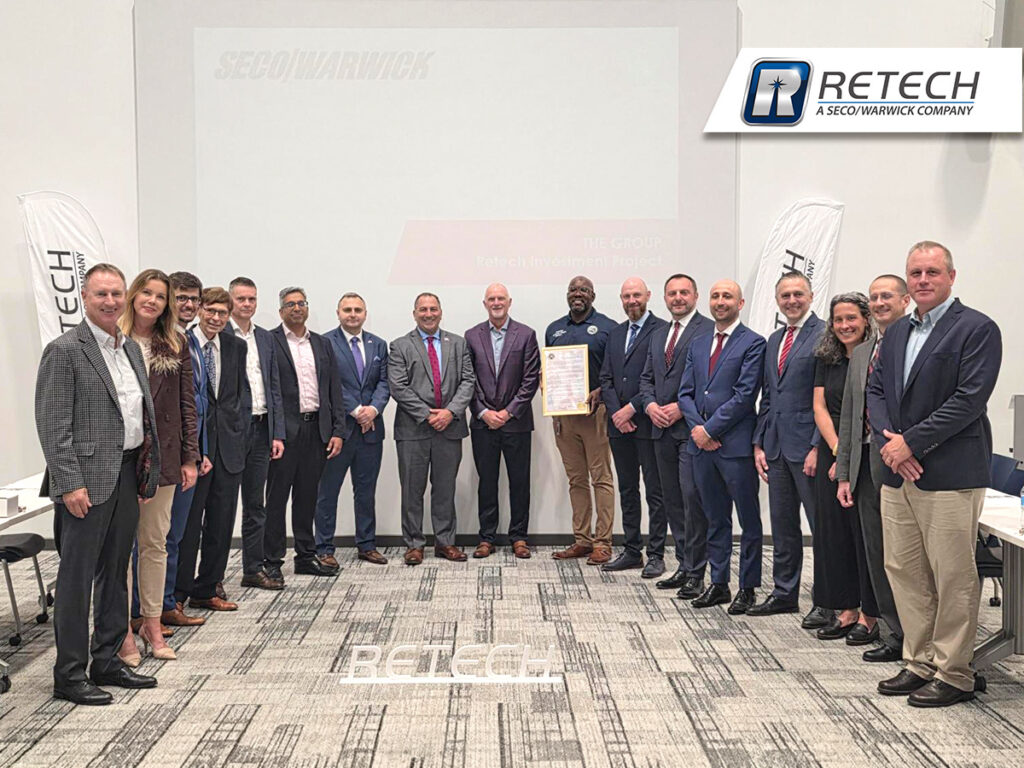
SECO/WARWICK concludeds Retech’s Strategic Investment Project in the U.S. | Image Credit: Retech
SECO/WARWICK and Retech marked the completion of the project during a ceremony at Retech’s facility in Buffalo, New York. Attendees of this milestone event to commemorate the expansion of Retech’s capabilities included representatives from PFR TFI, the Embassy of the Republic of Poland in Washington, D.C., and the U.S. Congress.
The event program included presentations on the growth of the SECO/WARWICK Group, the company’s operations in the United States, Retech’s technological capabilities, and the results of the investment project. Participants also toured Retech’s laboratories and technological facilities, where the Group’s U.S. company presented its processes and solutions. The investment expands Retech’s infrastructure, research, and technology base to support client needs across industrial markets.
Earl Good Managing Director Retech Systems, LLC Source: Retech
“This project is strategically important for Retech. It enables us to expand our technological capabilities, develop our laboratory resources, and respond even more effectively to the needs of [clients] operating in the most demanding industries. Buffalo is an important point on the U.S. industrial map, and Retech, as part of the SECO/WARWICK Group, combines American engineering expertise with the organization’s global potential,” emphasized Earl Good, managing director of Retech.
The project was co-financed by the Foreign Expansion Fund 2 FIZ AN. As part of the cooperation, Retech secured a long-term $10 million loan from the Fund for the development of metal powder production technology, including the development and installation of plasma gas atomizer (PGA) furnaces and the expansion of manufacturing and assembly operations. The investment was undertaken to support continued growth in advanced metallurgical technologies and related markets.
Image Credit: SECO/WARWICK Group
Press release is available in its original form here. Main image shows the shop floor at Retech’s headquarters in Buffalo, New York. Image Credit: Retech
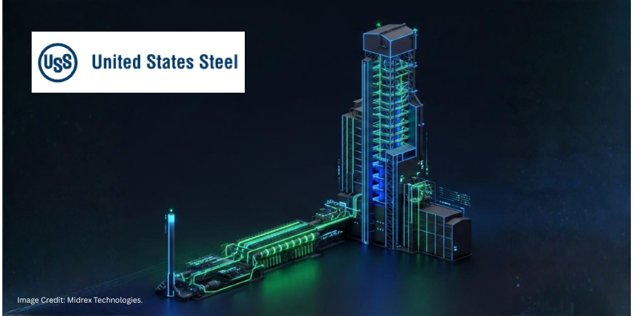
A new direct reduced iron (DRI) facility planned for U.S. Steel’s Arkansas-based steelmaking facility, Big River Steel Works, in Osceola, Arkansas, is expected to strengthen domestic steelmaking capabilities by linking iron ore production, ironmaking, and electric arc furnace (EAF) steel production within a single U.S.-based supply chain. The facility will produce hot direct reduced iron (HDRI) and hot briquetted iron (HBI) for use in downstream steel melting operations, supporting domestic steel production with a U.S.-based source of metallic feedstock.
The project is part of a $1.9 billion investment by U.S. Steel to construct a DRI facility adjacent to its Big River Steel Works operation. Once in service, the facility is expected to produce approximately 2.5 million metric tons of HDRI annually to support steel production at the site.
The DRI facility will process iron ore pellets sourced from U.S. Steel’s Minnesota Ore Operations, creating a domestic production pathway from iron ore mining through ironmaking and steel melting. The HDRI produced at the facility will be fed directly into the steelworks’ EAF operations, while HBI can be used as a metallic feedstock for steel production and transportation.
To support the project, Midrex Technologies was selected to provide its MIDREX Flex® technology, which is designed to operate on natural gas while allowing for increased hydrogen use as supporting infrastructure and supply become available. The facility plans to be the first U.S.-based DRI plant designed to produce both HDRI and HBI.
Construction is expected to begin in 2027, with startup anticipated in 2029. The project is part of U.S. Steel’s strategy to expand steelmaking capacity and strengthen a domestic “mine-to-melt” steel supply chain. It is expected to support production of steel grades for automotive, electrical, and industrial applications.
Press release is available in its original form here. Main image shows the Big River Steel MIDREX plant model. Image Credit: Midrex Technologies
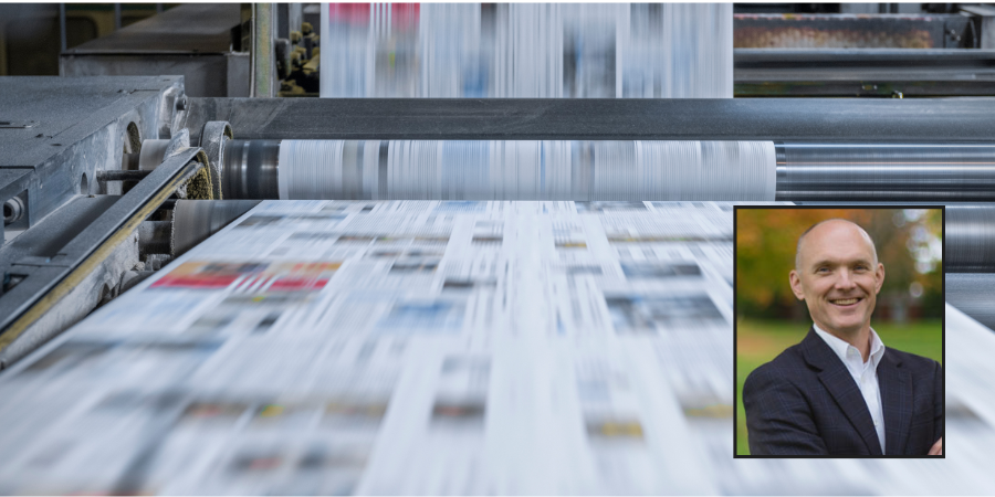
Heat Treat Today publishes twelve print magazines annually and included in each is a letter from the publisher, Doug Glenn. This letter from the May 2026 Sustainable Heat Treat Technologies print edition challenges the assumption that digital-only communication is the future, citing Heat TreatToday’s own subscription data and industry research to argue that print and tactile media are making a meaningful comeback.
46% of Gen Z say that they are taking steps to limit their screen time according to an extremely interesting article by Rocco Nugent in a recent print edition of The Epoch Times national weekly newspaper. In the same article, Nugent states that somewhere between 180,000 and 750,000 U.S. households are now living off the grid to some degree. Digital minimalism is officially “a thing.”
As you can imagine, the way Heat TreatToday’s audience consumes information is of immense interest to us. And, as you may not imagine, this curtailing and even abandonment of digital media is no surprise to our team. For many of you reading this column by holding a hardcopy in your hand, you also might not be surprised. But for those of you who are fighting with your upper management about whether to go all digital or do the more moderate approach of combining digital and “old-fashioned” tactile forms of communication, here are some facts that should help the cause.
70% of all subscriptions received by Heat TreatToday — and other trade journal publishers based on informal research — are for hardcopy print magazines. This is true across all age categories. We offer subscriptions to digital editions of the magazine and industry e-newsletters. Seven out of ten of these subscriptions include a request to receive the hardcopy magazine. They typically ask for at least one other digital subscription, but a full 70% request a hardcopy magazine. This is counter intuitive in what many wrongly believe is a digital-only age.
According to a study published by The Harris Poll in partnership with Quad, there has been a marked move back to tactile marketing efforts like hardcopy mailers, postcards, letters, and magazines because of the substantially better results (Quad 2025). They dub this effect “return of touch” — as opposed to return on investment (ROI). Most digital marketing campaigns brag about their ROI, but this study asserts that return of touch is now winning the day. People, including those Gen Zers mentioned above, are hungering for something more tangible, something they can touch and hold. Apparently, when you spend your entire day in front of a screen, it’s enjoyable to get away and grab something physical.
Heat TreatToday digital magazine subscriptions peaked at roughly 25% of our circulation 10 years ago; since then, it has steadily declined. Today, it is at or below 20%. That is to say, if you look at only magazine subscriptions, 20% or below are asking for digital-only subscriptions. In fact, we know that of the people who request digital editions, the number who look at their digital edition is not substantial. After decades of interacting with trade publishers and magazines, I can state that this is true across nearly all industrial trade magazine brands, not just Heat TreatToday.
All of this leads us to a simple conclusion: those who believe that we are in a digital age and that digital-only communication and marketing practices are the future, are mistaken. A small percentage of the companies we do business with have digital marketing firms. By default, these marketing companies, as their names indicate, have focused on digital marketing because they believed it was the future… back in the early 2000s. Unsurprisingly, these digital marketing companies would badmouth hard copy magazines and mailers, but that’s because their whole company existence is predicated on digital marketing assets. They were biased from the start.
Heat TreatToday has a horse in both races, so we are somewhat agnostic about whether a company goes all digital or maintains a more balanced approach. We just hate to see companies hurt themselves by believing that digital-only is the way to go when it is demonstrably not. You need to have digital. We are not in favor of throwing the baby out with the bath water, but a digital-only world is one where you will be missing up to 70–80% of your target audience.
References
Nugent, Rocco. 2026. “Silent Revolution.” The Epoch Times. March 11–17, 2026. p. A15.
Quad. 2025. “Return of Touch: Consumer Engagement Has an Omnichannel Revival.” May 13, 2025. https://www.quad.com/resources/research-and-tools/return-of-touch-consumer-engagement-has-an-omnichannel-revival.
Doug Glenn Publisher Heat TreatToday For more information: Contact Doug at doug@heattreattoday.com