"A compressive surface stress can benefit bend fatigue performance by reducing the mean stress experienced during service, effectively offsetting the tensile stress generated by the cyclic loading conditions." In this Technical Tuesday by Justin Sims of DANTE Solutions, learn how a simulation program, funded by the U.S. Army, modeled the method of Intensive Quenching®.
This article covers Phase 2 of the project, a follow up to an article that was previously featured on Heat TreatToday. Check out more original content articles in this digital edition or other editions here.
Justin Sims Lead Engineer DANTE Solutions
Helicopter powertrain gearing can be subjected to tremendous loads during service. The high tensile loads experienced in the root of the gear tooth, combined with the cyclic loading conditions inherent in gear operation, can lead to cyclic bend fatigue failures. To improve cyclic bend fatigue performance, low alloy steels are often carburized and quenched. The combination of a high carbon case and low carbon core leads to increased strength and hardness in the carburized case, while maintaining a tough core. In this manner, the case resists wear and can carry a high load without fracture, while the core is able to absorb the energy imparted to it during operation. Besides the increased strength and hardness, the addition of carbon creates a chemical gradient from the surface of the component towards the core. The carbon gradient creates delayed martensite transformations, relative to the low carbon in the core, and is responsible for imparting residual compressive surface stress. A compressive surface stress can benefit bend fatigue performance by reducing the mean stress experienced during service, effectively offsetting the tensile stress generated by the cyclic loading condition
Since the timing of the transformation to martensite is the main driver in the generation of compressive residual surface stresses, it is possible, to some extent, to control the magnitude of the surface stress by changing the quenching process. Historically, transmission gears have been carburized and quenched in oil. However, as more and more attention is paid to improving part performance through processing techniques, other forms of quenching have become available that show promise in increasing surface compressive stresses, and thereby improving bend fatigue performance. Of particular interest, is a quenching method which utilizes high pressure, high velocity water to quench parts.
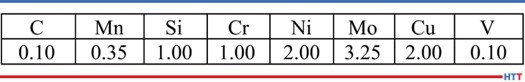
Table 1. Pyrowear 53 nominal chemistry.
Known as Intensive Quenching®, the method was developed by Dr. Nikolai Kobasko as an alternative means of quenching components to achieve deep residual surface compression and improve bend fatigue performance.1–3
The technology works by inducing a large temperature gradient from the surface to the core of the component. In non-carburized components, the process has been shown to provide an extremely rapid and uniform transformation to martensite in the surface layers, while the core remains austenitic. This creates a hard shell, under extreme compression. As the part continues to cool, the surface is pulled into an even deeper state of compression. As the core transforms, some compression is lost due to the expanding core, but the compression that remains is generally greater than that achieved by oil quenching.4–7
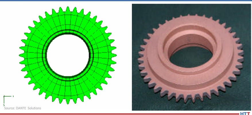
Figure 1. Gear CAD model (left) and actual test gear (right).
To evaluate the possibility of improving bend fatigue of helicopter transmission gears, a program was conceived to compare the bend fatigue performance of carburized gears quenched in oil versus carburized gears quenched using the Intensive Quenching process. Funded by the US Army, the project was comprised of two phases. Phase 1, described in a previous Heat Treat Today article, was a proof-of-concept phase, designed to prove that intensively quenched components could outperform oil quenched components in high cycle bend fatigue testing. Phase 2 then moved to actual transmission gear testing. DANTE heat treatment simulation was used extensively throughout the project to guide processing decisions and understand the mechanisms responsible for improved bend fatigue performance though the creation of residual surface compression. This article will examine Phase 2 of the project.
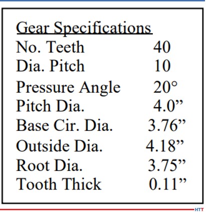
Table 2. Test gear specifications.
Pyrowear 53 was the material of choice for the project, as it is used extensively in helicopter power transmission gearing. Table 1 lists the nominal alloy chemistry for Pyrowear 53, which is a low-carbon, carburizing grade of steel. Figure 1 shows a CAD model of the test gear (left) and a picture of an actual test gear (right); the actual test gear is copper plated to selectively carburize only the gear teeth. The gears were carburized as one batch, and then hardened and tempered to a tooth surface hardness of 59 HRC and a core hardness of 42 HRC. An oil quenching process was used to harden half of the gears and an Intensive Quenching process was used to harden the other half of the gears. Table 2 lists the dimensional specifications of the gear.
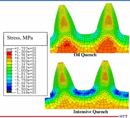
One benefit of using the Intensive Quenching process over a conventional oil quenching process is the development of high residual surface compression. Compressive surface stresses benefit fatigue performance by offsetting any tensile stress generated during loading, effectively reducing, or eliminating, the tensile load experienced by the material. Figure 2 compares the residual stress predicted by DANTE for the test gear subjected to an oil quenching process (top) and an Intensive Quenching process (bottom). It is clear that the Intensive Quenching process induces a greater magnitude of compression in the area of the tooth root, which is the location of most gear bending fatigue failures. The residual stresses present in the tooth flank appear equivalent between the two quenching processes, but the oil quenched component has higher tensile stresses under the carbon case. This could lead to problems should any inclusions or material defects be present in that location.
Figure 2. Residual stress prediction for test gear, comparing oil quench and Intensive Quench.
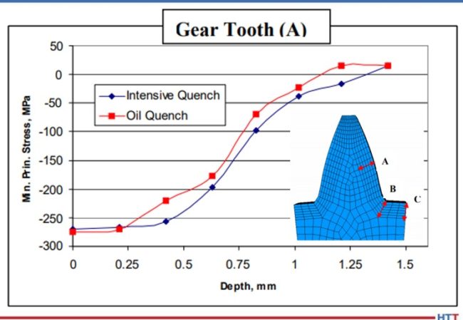
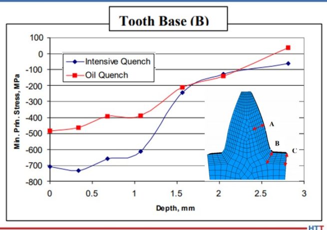
Figures 3 – 5 compare the residual stress profiles of the two gears at three gear tooth locations: flank, root-fillet, and root, respectively. The residual stress profiles for the two processes at the tooth flank, shown in Figure 3, are equivalent, as inferred from the contour plots shown in Figure 2. Both quenching processes generate a surface compressive stress of 275 MPa on the tooth flank. However, the residual stress profiles in the root area of the gear vary greatly between the two processes. Figure 4 shows the residual stress profile at the root-fillet, which is the location of the highest tensile stress during gear service. At this location, the rapid surface cooling afforded by the Intensive Quenching processes creates a large temperature gradient from the surface to the core, allowing more thermal shrinkage to occur after the surface transforms to martensite. The additional thermal shrinkage, combined with the concave geometry of the gear root area, creates additional compressive stresses in this area.
Figure 3. Residual stress versus depth prediction for test gear at point A, comparing oil quench and Intensive Quench.
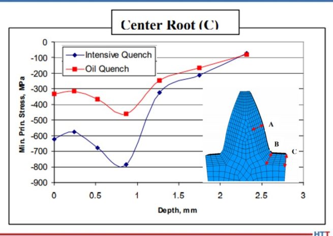
Figure 4 shows that the Intensive Quenching process generated a compressive stress of 700 MPa on the surface of the root-fillet, while the oil quenched gear produced a 500 MPa compressive surface stress in this location. The intensively quenched gear also has a deeper layer of high compression, not rising above 600 MPa compression until after 1 mm below the surface. Figure 5 shows a similar trend for the root, but with an even larger difference between the two quenching processes, since the geometry is even more concave at this location. Again, the gear subjected to the Intensive Quenching process has high compression up to 1 mm under the surface and a compressive surface stress magnitude 300 MPa higher than the oil quenched gear at the root location. The modeling results indicate that the intensively quenched gears should outperform the oil quenched gears in bend fatigue given the increased surface compressive stress present.
Figure 4. Residual stress versus depth prediction for test gear at point B, comparing oil quench and Intensive Quench.
Figure 5. Residual stress versus depth prediction for test gear at point C, comparing oil quench and Intensive Quench.
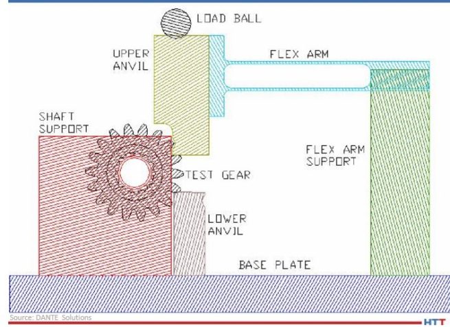
All of the hardened gears were tested at the Gear Research Institute, located at Pennsylvania State University in State College, PA, using a servo-hydraulic testing machine with a specially designed fixture to apply a cyclic bending load to two teeth. A schematic of the fixture is shown in Figure 6. A load ratio of 0.1 was used for all fatigue tests to ensure the gear did not slip during testing by having a constant tensile load applied. The fatigue test was considered successful, defined as a runout, if the gear completed 107 cycles given a certain maximum load. The maximum bending stress, calculated for a stress-free initial condition, was used to compare the two processes.
Figure 6. Schematic of fatigue testing apparatus.
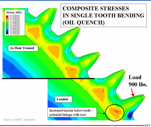
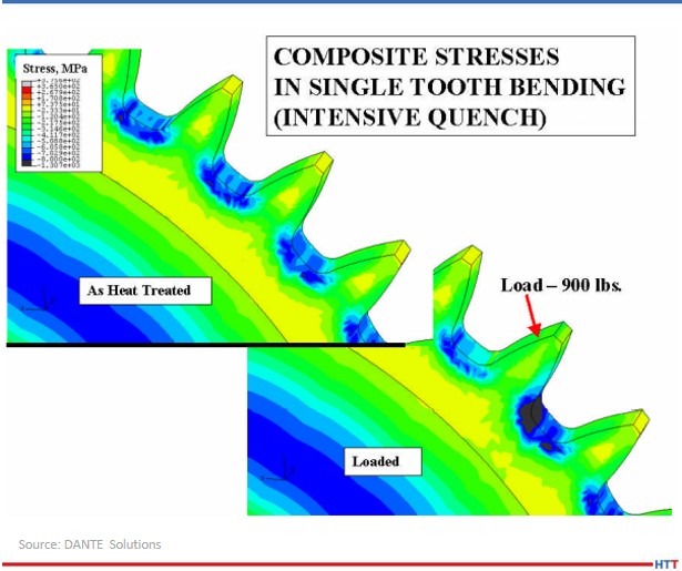
As previously mentioned, the effect of residual compressive stresses during tensile bend fatigue is to offset the tensile stress generated by the load. Figure 7 shows a DANTE model of the test gear subjected to oil quenching showing the residual stress from heat treatment (top) and the stress redistribution during the application of a 900 lb. load (bottom). Figure 8 shows the same conditions for the test gear subjected to the Intensive Quenching process. As can be seen from the two figures, in which the legend ranges are the same, there is substantially more compressive stress remaining in the root-fillet area of the gear subjected to the Intensive Quenching process when the load is applied. This means the effective stress experienced by the intensively quenched gear is less than that of the oil quenched gear, given an identical load.
Figure 7. Stress predictions for the oil quenched gear, showing the residual stress from heat treatment (top) and the stress change when a 900 lb. load is applied (bottom).
Figure 8. Stress predictions for the Intensive Quenched gear, showing the residual stress from heat treatment (top) and the stress change when a 900 lb. load is applied (bottom).
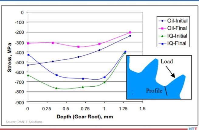
Figure 9 shows the residual stress profile from the surface at the root-fillet for both processes, in the unloaded and loaded conditions. From the plot, a load of 900 lb. generates a tensile stress of approximately 200 MPa, which is offset by the compressive residual stresses. With a 900 lb. load, neither gear sees any tensile stresses during loading, and thus, should runout during fatigue testing.
Figure 9. Comparison of predicted stresses versus depth for the oil quench and Intensive Quench gears in the unloaded (Initial) and loaded (Final) state.
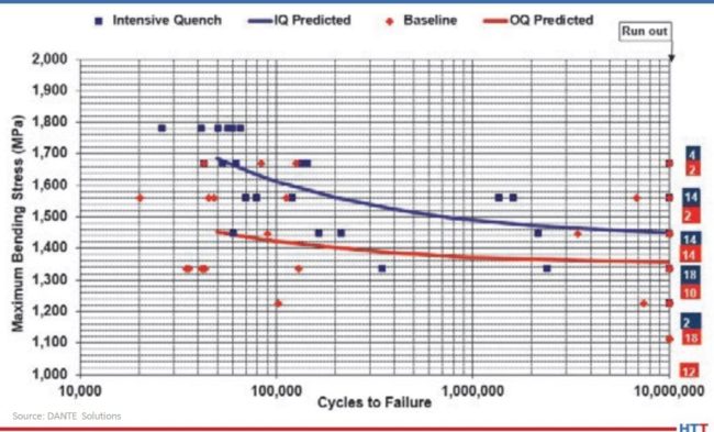
Figure 10 shows the results of the fatigue testing. As expected, the gears subjected to the Intensive Quenching process have an increase in fatigue performance. The endurance limit of the intensively quenched gears is approximately equal to the difference in surface compression, though additional tests should be conducted to confirm this. Regardless, increasing the magnitude of surface compression through a process change can significantly improve fatigue performance of power transmission gearing.
Figure 10. S-N curves for the oil quench and Intensive Quench gears tested.
In conclusion, achieving higher residual surface compressive stresses during hardening of a carburized power transmission gear by way of a process change was shown to improve bend fatigue performance. This was confirmed by the company's simulations, which showed a significant increase in compressive surface and near-surface stresses when the gear was quenched using the Intensive Quenching process, as opposed to an oil quench. The cause of the increased compression was determined from simulations to be due to the combination of martensite formation in the surface layers of the gear and the accompanying thermal shrinkage of the austenitic core, which draws concave geometric features, such as a gear tooth root, into a higher state of compression. The large temperature gradient induced during the Intensive Quenching process is necessary to produce these conditions. Physical fatigue testing confirmed the simulation results, showing a significant improvement in fatigue performance for the gears quenched using the Intensive Quenching process. Accurate process simulation pointed to a heat treatment process change that could be used to achieve increased power density through a transmission as opposed to more expensive and time-consuming design changes.
N. I. Kobasko and V. S. Morganyuk, “Numerical Study of Phase Changes, Current and Residual Stresses in Quenching Parts of Complex Configuration,” Proceedings of the 4th International Congress on Heat Treatment of Materials, Berlin, Germany, 1 (1985), 465-486.
N. I. Kobasko, “Intensive Steel Quenching Methods. Theory and Technology of Quenching”, SpringerVerlag, New York, N.Y., 1992, 367-389.
N. I. Kobasko, “Method of Overcoming Self Deformation and Cracking During Quenching of Metal Parts,” Metallovedenie and Termicheskay Obrabotka Metallov (in Russian), 4 (1975), 12-16.
M. Hernandez et al., Residual Stress Measurements in Forced Convective Quenched Steel Bars by Means of Neutron Diffraction”, Proceedings of the 2nd International Conference on Quenching and the Control of Distortion, ASM, (1996), 203-214.
M. A. Aronov, N. I. Kobasko, J. A. Powell, J. F. Wallace, and D. Schwam, “Practical Application of the Intensive Quenching Technology for Steel Parts,” Industrial Heating Magazine, April 1999, 59-63.
A. M. Freborg, B. L. Ferguson, M. A. Aronov, N. I. Kobasko, and J. A. Powell, Intensive Quenching Theory and Application for Imparting High Residual Surface Compressive Stresses in Pressure Vessel Components,” Journal of Pressure Vessel Technology, 125 (2003), 188-194.
B. L. Ferguson, A. M. Freborg, and G. J. Petrus, “Comparison of Quenching Processes for Hardening a Coil Spring,” Advances in Surface Engineering, Metallurgy, Finishing and Wear, SAE (01) 1373, (2002).
About the Author: Justin Sims has been with DANTE Solutions for eight years and is an excellent analyst and expert modeler of steel heat treat processes using the company's software. His project work includes development, execution, and analysis of carburization, nitriding, and quench hardening simulations. For more information, contact Justin at justin.sims@dante-solutions.com.
What do helicopter gears and heat treat modeling have to do with improving the bend fatigue performance of low-alloy gear steels? Find the answer in this interesting case study which analyzes the effects on compressive surface stress caused by changing the heat treating process.
This Technical Tuesday is provided by Justin Sims of DANTE Solutions and was featured in the Heat TreatToday's 2021 March Aerospace print edition. Check out more original content articles in this digital edition or other editions here.
Introduction
Justin Sims Lead Engineer DANTE Solutions
Helicopter powertrain gearing can be subjected to tremendous loads during service. The high tensile loads experienced in the root of the gear tooth, combined with the cyclic loading conditions inherent in gear operation, can lead to cyclic bend fatigue failures. To improve cyclic bend fatigue performance, low-alloy steels are often carburized and quenched. The combination of a high carbon case and low carbon core leads to increased strength and hardness in the carburized case, while maintaining a tough core. In this manner, the case resists wear and can carry a high load without fracture, while the core is able to absorb the energy imparted to it during operation.
Besides the increased strength and hardness, the addition of carbon creates a chemical gradient from the surface of the component towards the core. The carbon gradient creates delayed martensite transformations relative to the low carbon in the core and is responsible for imparting residual compressive surface stress. A compressive surface stress can benefit bend fatigue performance by reducing the mean stress experienced during service, effectively offsetting the tensile stress generated by the cyclic loading conditions.
Most gear steels contain enough alloying elements to guarantee a transformation to martensite upon quenching to room temperature from the austenite phase field. It is well known that the martensite starting temperature is significantly influenced by the amount of carbon in austenite at the time of transformation, with higher amounts of carbon generally lowering the martensite start temperature. This means the chemical gradient present after carburizing creates a nonuniform phase transformation, with the transformation starting at the base carbon just below the carburized case and progressing inward toward the core.
As the martensite is formed, the atomic rearrangement results in a volume expansion, causing a tensile stress to form on the surface as the core material pushes out on the surface. As the component continues to cool, the martensite start temperature is reached in the carbon rich case, usually well after the core has transformed to martensite or bainite, depending on the cooling rate. The transformation in the case progresses outward, with the surface being the last to transform. This core-to-surface transformation results in a compressive surface stress since the volumetric expansion created by the martensite transformation at the surface is constrained by the core material.
Because the timing of the transformation to martensite is the main driver in the generation of compressive residual surface stresses, it is possible, to some extent, to control the magnitude of the surface stress by changing the quenching process. Historically, transmission gears have been carburized and quenched in oil. However, as more attention is paid to improving part performance through processing techniques, other forms of quenching have become available that show promise in increasing surface compressive stresses, and thereby improving bend fatigue performance. Of particular interest is a quenching method which utilizes high pressure, high velocity water to quench parts.
Figure 1. DANTE residual stress predictions comparing a gear subjected to oil quenching and intensive quenching
Known as Intensive Quenching®, the method was developed by Dr. Nikolai Kobasko as an alternative means of quenching components to achieve deep residual surface compression and improve bend fatigue performance.1-3 The technology works by inducing a large temperature gradient from the surface to the core of the component. In non-carburized components, the process has been shown to provide an extremely rapid and uniform transformation to martensite in the surface layers, while the core remains austenitic. This creates a hard shell under extreme compression. As the part continues to cool, the surface is pulled into an even deeper state of compression. As the core transforms, some compression is lost due to the expanding core, but the compression that remains is generally greater than that achieved by oil quenching. 4 – 7
To evaluate the possibility of improving bend fatigue of helicopter transmission gears, a program was conceived to compare the bend fatigue performance of carburized gears quenched in oil versus carburized gears quenched using the Intensive Quenching process. Funded by the U.S. Army, the project was comprised of two phases. Phase One was a proof-of-concept phase, designed to prove that intensively quenched components could outperform oil quenched components in high cycle bend fatigue testing. Phase Two then moved to actual transmission gear testing. DANTE Solutions Inc. heat treatment modeling was used extensively throughout the project to guide processing decisions and understand the mechanisms responsible for improved bend fatigue performance through the creation of residual surface compression. This article will explore Phase one, with Phase two covered in a follow up article.
Phase One
Before any testing was initiated, the company heat treatment simulation was executed to compare the residual stress induced in a gear tooth root from oil quenching and Intensive Quenching. As can be seen in Figure 1, using Intensive Quenching significantly increased the near surface residual compression. This increase in compression should result in an increase in bend fatigue performance. Satisfied with these preliminary results, a testing regiment was initiated.
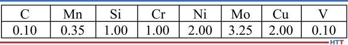
Table 1. Pyrowear 53 base chemistry
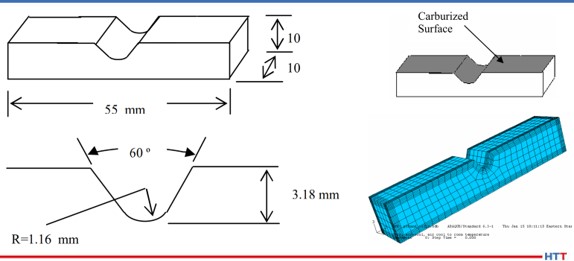
Figure 2. Coupon dimensions, selectively carburized surface, and finite element model
The steel alloy Pyrowear® 53 was chosen as the candidate material for this project. Table 1 shows the base chemistry of Pyrowear 53. The alloy is used extensively in the aerospace industry as a transmission gear material due to its ability to resist softening at high temperature in the hard carburized case, while maintaining high core impact strength and fracture toughness. A specially designed “V” notch 3-point bend fatigue sample was created by the company in conjunction with input from experts at the Army Gear Research Lab at NASA-Glenn and Bell Helicopter. The design was chosen to mimic behavior of a gear tooth root during loading. Figure 2 shows the dimensions of the coupon, the selectively carburized surface, and the finite element model used to explore the effects of process parameter changes on residual stress.
Figure 3. Schematic of intensive quenching orientation for Phase 1 study
A total of 40 coupons were manufactured and selectively carburized. The coupons were then split into two groups. Both groups were subjected to the same 1674°F (912°C) austenitizing, - 110°F (-79°C) cryogenic treatment, and double temper at 450°F (232°C). However, the two groups differ in the method of quenching, with one group quenched using the standard oil quenching practice for Pyrowear 53 and the second group quenched using the Intensive Quenching method. The two groups were processed separately. The Intensive Quenching unit utilized in this project uses a high velocity water stream to quench one component at a time. Figure 3 shows the coupon orientation within the intensive quenching unit. The blue arrow indicates the direction of water flow over the coupon.
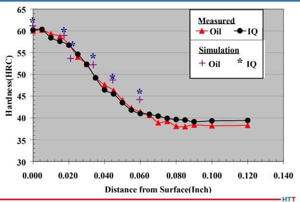
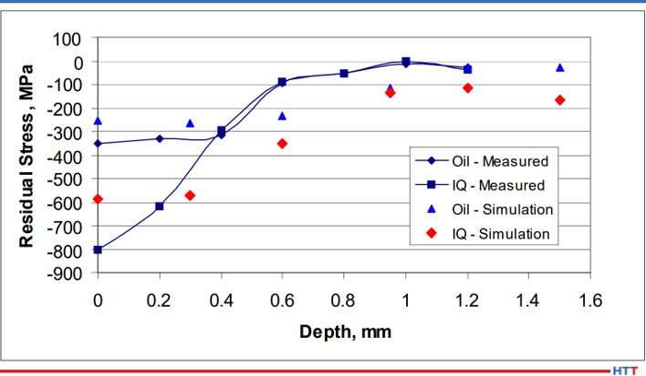
After processing all of the coupons and modeling the two processes using the same heat treatment simulation software, a comparison was made between the two processes and the simulation. Figure 4 shows the hardness profile comparison at the center of the notch. As seen, the hardness profiles are equivalent between the two processes. This is expected as the carbon and other alloy content in the material is identical between the two processes. The simulation also matches the experimental data well. While the hardness profiles are identical between the two processes, the residual stress profiles at the center of the notch are not the same, as shown in Figure 5. The intensively quenched coupon has a surface compressive stress of 800 MPa, more than double the compression induced by oil quenching. However, at 0.4 mm, the profiles converge. This is significant as the surface can now carry a higher load, yet no detrimental effects are seen subsurface. Again, the simulation matches the experimental results well.
Satisfied with the increased surface compressive stress gained through the use of Intensive Quenching, 3-point bend fatigue testing was initiated at Case Western Reserve University. Load control was applied, with a minimum to maximum load ratio of 0.1 used to maintain a state of cyclic tension. This type of loading ensures the sample remains stationary throughout the duration of the test.
Figure 4. Phase 1 hardness profile comparison between oil quench, Intensive Quench, and DANTE simulations of the two processes
Figure 5. Phase 1 residual stress profile at the notch center comparison between oil quench, intensive quench, and DANTE simulations of the two processes
Figure 6 shows the results of the bend fatigue testing. It appears from Figure 6 that the increased residual surface compression of the intensively quenched coupons contributed to an increase in bend fatigue performance when compared to the oil quenched samples. However, some scatter does exist. Several parameters could have influenced these results.
First, during coupon manufacturing, the notch was created in the coupon using a milling operation and then heat treated. After heat treatment, no finishing operation was performed on the notch. Therefore, the possibility of surface defects existed. Any surface defect can create a stress riser, creating a stress condition which exceeds the expected stress given the loading conditions and geometry. However, surface defects would not be consistent coupon to coupon, and therefore have the potential to skew fatigue results.
Figure 6. Phase 1 bending fatigue comparison between oil quench and intensive quench
The second parameter that could have influenced the scatter in the fatigue results is related to the intensive quenching process itself. The process is dependent on a steep temperature gradient to generate the greatest level of compressive stress. This requires high velocity water to impact the component quickly, as any delay or low velocity water impingement can create shallow temperature gradients. Using the DANTE software, it was determined that in order to generate the greatest amount of surface compression, full flow must be achieved in a maximum of one second. This was a significant discovery that may have gone unnoticed if simulation was not used to explore process parameter sensitivities. It was unclear if the equipment operation met this maximum time restraint during processing of all coupons. However, due diligence was given to system operation in future experiments with improved consistency.
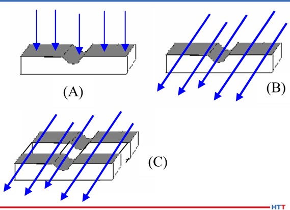
Figure 7. Schematic of intensive quenching orientations for Phase 1A study
Another processing parameter that has the potential to influence residual stress generated during an intensive quenching operation is the orientation of certain geometric features relative to the high velocity water flow. Again, the DANTE software was utilized, in lieu of expensive physical testing, to determine the optimum orientation of the fatigue sample in the intensive quenching unit. Figure 7 shows the three orientations evaluated. The orientation in Figure 7(A) has the water impinging on the notch surface and Figure 7(B) has the water impinging on the side of the coupon, with water flowing parallel to the notch. Recall that the original coupon orientation, shown in Figure 3, has the water impinging on the top of the coupon and flowing perpendicular to the notch. The final configuration, shown in Figure 7(C), places two coupons in the chamber side-by-side. This configuration has the potential to create an even steeper thermal gradient within the coupon due to the two coupons sharing thermal energy from being in contact with one another, and thus having a slower cooling rate in the core than a single coupon.
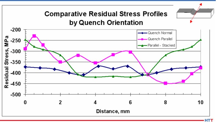
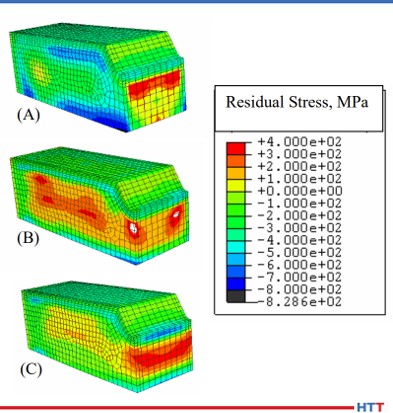
Figure 8 shows the surface residual stress across the width of the notch center, as shown by the red arrow in the Figure 8 inset, for the three orientations predicted by the simulation. Of the three orientations evaluated, orientation (A) resulted in the greatest magnitude of compression, as well as remaining the most consistent across the width of the notch. The residual stress contour plots of the three orientations, shown in Figure 9, confirm the uniformity of the residual stress profile across the width of the notch for orientation (A). The other two orientations show markedly reduced compressive surface stress near the edges of the notch. This type of profile would most likely fail in fatigue at those locations with reduced surface compression. To achieve the most consistent performance results, the most uniform surface condition should be sought.
Figure 8. DANTE residual stress profile predictions across the width of the notch center, as shown schematically in the figure inset, for the Phase 1A study
Figure 9. DANTE residual stress predictions for the Phase 1A study
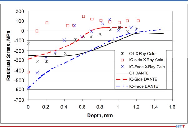
The residual stress profiles at the center of the notch are shown in Figure 10 for oil quenched coupons, intensively quenched coupons with orientations (A) (“IQ-face”) and orientation (B) (“IQ-side”), and the company simulation results for the three processes. As predicted by simulation, and confirmed by X-ray diffraction measurements, the intensively quenched coupon in orientation (A) results in the highest magnitude of residual surface compressive stress, as well as having the deepest compression. The measurements also revealed that intensively quenching the coupon geometry in orientation (B) results in a slight increase in surface compression, when compared to oil quenching, but the compression is reduced much quicker in the orientation (B) coupon. Based on the simulation results, it was surmised that orientation (A) would outperform orientation (B) in bend fatigue, and oil quench would outperform orientation (B). Due to the poor residual stress distribution predicted for orientation (C), no coupons were processed in this orientation.
Figure 10. Residual stress profile measurements and predictions at the notch center for orientations A and B of the Phase 1A study
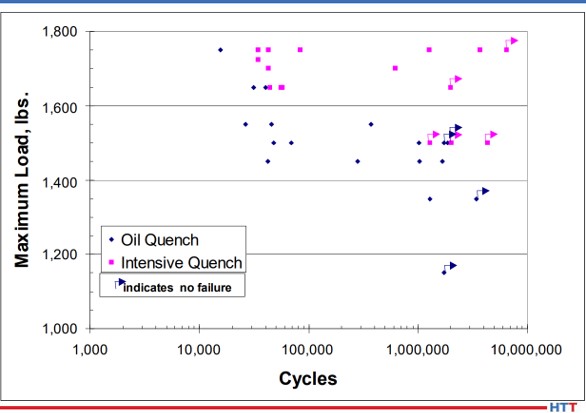
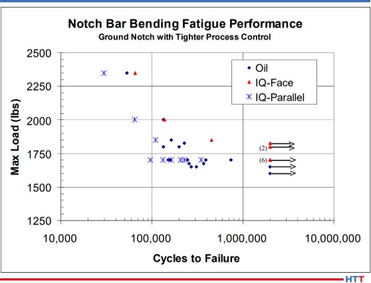
Figure 11 shows the bend fatigue results for the oil quenched coupons and the intensively quenched coupons in orientation (A) (“IQ-Face”) and orientation (B) (“IQ-Parallel”). As predicted from information gleaned from the DANTE simulation, orientation (A) outperformed the oil quenched coupons. The orientation (A) coupon recorded an endurance limit of approximately 1800 MPa, while the oil quenched coupons recorded an endurance limit of approximately 1600 MPa. This difference is approximately equal to the difference in near surface compressive stress induced by the two processes. The orientation (B) coupons failed to successfully complete a test at the loads chosen. Convinced that increasing the magnitude of surface compression through a process change could improve fatigue performance in transmission gears, Phase Two was initiated to evaluate the process change on an actual gear component.
Figure 11. Phase 1A bending fatigue comparison between oil quench and Intensive Quench
Conclusion
In conclusion, a project was launched to use heat treatment modeling, in conjunction with physical testing, to determine the effects of a process change designed to induce a greater magnitude of compressive surface stress to improve bend fatigue performance of a low-alloy gear steel. Pyrowear 53 was chosen as the gear steel and Intensive Quenching was chosen as the process change to induce a greater magnitude of residual surface compressive stress. Before any testing was initiated, DANTE modeling was used to show that intensive quenching could indeed produce a greater magnitude of surface compression, possibly improving bend fatigue performance by introducing a compressive mean stress and lowering the actual stress witnessed by the component. This modeling was also used to determine the maximum amount of time which may be used by the intensive quenching equipment to reach a full flow condition and still produce an increase in residual surface compression, as well as evaluate the residual stress profile of several different intensive quenching orientations.
Using this modeling to direct physical testing, hardness, residual stress, and bend fatigue performance were evaluated in coupons quenched in oil and coupons intensively quenched in three different orientations. The fourth orientation was not tested as modeling showed the residual stress profile to be unfavorable. Physical testing confirmed the modeling results: hardness profiles are equivalent between the processes, and residual stress profiles coincide with modeling results. Bend fatigue performance was indeed increased by increasing the magnitude of surface compressive stress. Phase One of the project showed that bend fatigue performance was improved by increasing the magnitude of the part’s surface compressive stress and demonstrated that modeling can be an invaluable tool when evaluating process parameter changes on material performance.
References
1. N. I. Kobasko and V. S. Morganyuk, “Numerical Study of Phase Changes, Current and Residual Stresses in Quenching Parts of Complex Configuration,” Proceedings of the 4th International Congress on Heat Treatment of Materials, Berlin, Germany, 1 (1985), 465-486.
2. N. I. Kobasko, “Intensive Steel Quenching Methods. Theory and Technology of Quenching”, SpringerVerlag, New York, N.Y., 1992, 367-389.
3. N. I. Kobasko, “Method of Overcoming Self Deformation and Cracking During Quenching of Metal Parts,” Metallovedenie and Termicheskay Obrabotka Metallov (in Russian), 4 (1975), 12-16.
4. M. Hernandez et al., Residual Stress Measurements in Forced Convective Quenched Steel Bars by Means of Neutron Diffraction”, Proceedings of the 2nd International Conference on Quenching and the Control of Distortion, ASM, (1996), 203-214.
5. M. A. Aronov, N. I. Kobasko, J. A. Powell, J. F. Wallace, and D. Schwam, “Practical Application of the Intensive Quenching Technology for Steel Parts,” Industrial Heating Magazine, April 1999, 59-63.
6. A. M. Freborg, B. L. Ferguson, M. A. Aronov, N. I. Kobasko, and J. A. Powell, Intensive Quenching Theory and Application for Imparting High Residual Surface Compressive Stresses in Pressure Vessel Components,” Journal of Pressure Vessel Technology, 125 (2003), 188-194.
7. B. L. Ferguson, A. M. Freborg, and G. J. Petrus, “Comparison of Quenching Processes for Hardening a Coil Spring,” Advances in Surface Engineering, Metallurgy, Finishing and Wear, SAE (01) 1373, (2002).
About the Author: Justin Sims has been with DANTE Solutions for eight years and is an excellent analyst and expert modeler of steel heat treat processes using the DANTE software. His project work includes development, execution, and analysis of carburization, nitriding, and quench hardening simulations. He has developed the DANTE HELP packages and is the primary trainer and software support person for the DANTE software.
“Many metallurgists or heat treat engineers only think in terms of water or oil for quenching steel. Water is the most common quench medium, followed by oil. However, polymer quenchants have made significant inroads into these traditional choices…”
In today’s Technical Tuesday feature, Greg Steiger and Keisuke Kuroda of Idemitsu Lubricants America share an original content article on the composition and uses of polymer quenchants, specifically polyalkylene glycol.
Introduction
Greg Steiger Senior Key Account Manager Idemitsu Lubricants America
Many metallurgists or heat treat engineers only think in terms of water or oil for quenching steel. Water is the most common quench medium, followed by oil. However, polymer quenchants have made significant inroads into these traditional choices.
The advantages of water are abundance, low cost, lack of flammability, and the ability to achieve high hardness. Still, there are many disadvantages associated with water as well. These are all associated with the very aggressive quench obtained from water. Issues such as quench cracking, distortion and soft spots from uneven cooling are just a few of the drawbacks of water.
Keisuke Kuroda Technical Advisor Idemitsu Lubricants America
Oil quenchants do not offer the hardenability of a water quench because the quench speeds of oil are more limited than those of water. Quench oils also pose a fire hazard which can create workplace environmental issues such as smoke generated during the quench process. Additionally, the disposal costs of used quench oils continue to increase as time goes on. Limited options for applications requiring a quench speed between oil and water were available until water soluble polymers were introduced to the market in the mid-20th century.
With water soluble polymers heat treaters could vary the concentration in water to achieve oil like quench speeds. Furthermore, using warm or hot water provided the ability to increase the quench speed to approach that of water yet minimize the quench cracks and distortion due to the high quench severity of oils.
Historically, polymer quenchants were used in hardening steel and in nonferrous (aluminum) applications and continues to be a popular choice for these operations today. However, its use in induction hardening has grown exponentially, and as such, polymer quenchants have become much more important to modern manufacturing and heat treating.
1. Types of polymer quenchants
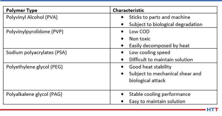
Today, there are many different types of polymers in use. Examples of these types of polymers include polyacrylates, polyvinyl alcohol, polyvinylpyrrolidone, polyethyloxazoline, polyethylene glycol and the most popular polyalkylene glycol (or PAG). The types of polymers and their characteristics are seen below in Table #1.
Table #1 Polymer types and their primary characteristics
While each of the chemistries listed in Table #1 are in use today, the scope of this paper will be limited to the most used chemistry, polyalkylene glycol.
1.1 Polyalkylene glycols and inverse solubility
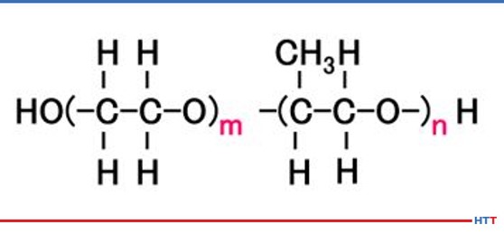
A polymer quenchant is composed of more than just the water-soluble polymer. In typical polyalkylene glycol polymer quenchants, water makes up the largest ingredient. However, there are additives such as ferrous corrosion inhibitors, nonferrous stain and oxidation inhibitors, alkalinity buffers, defoaming agent, biocides along with the polyalkylene glycol in typical polyalkylene glycol quenchants. Chemically, a polyalkylene glycol consists of nothing more than carbon, hydrogen, and oxygen. The chemical structure for a polyalkylene glycol is seen in Figure #1. The m and n represent the number of molecules contained in the polymer. The higher the values of m and n, the thicker and more viscous the polymer becomes.
Figure #1 Polyalkylene Glycol Chemical Structure
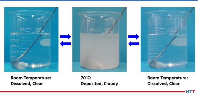
In examining the chemical structure of a polyalkylene glycol it can be seen there or OH and H molecules on each end of the polymer. As we learned in high school science classes, like dissolves like. Water is composed of these same compounds and this is why the polymer is soluble in water. However, a polyalkylene glycol exhibits inverse solubility at higher temperatures due to a phenomenon called a cloud point. At 70°C (approximately 160°F) the polyalkylene polymer becomes insoluble in water. By being no longer soluble in water the polymer then coats the part being quenched and controls the cooling rate to provide a slower quench speed than pure water thereby reducing or eliminating the risk of quench cracking and distortion. A demonstration of the cloud point phenomena is shown in Figure #2.
Figure #2 Polyalkylene Glycol Cloud point
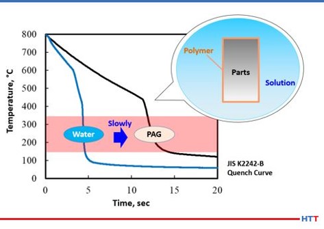
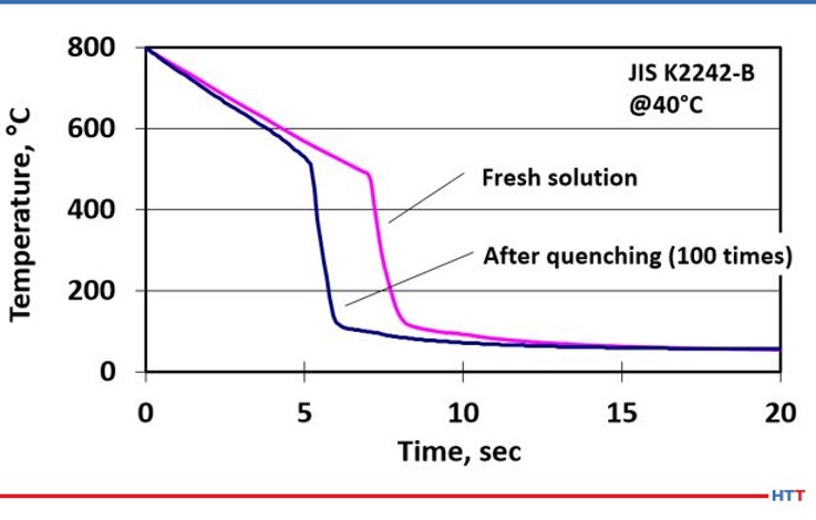
In examining cooling curves generated using the test method JIS K2242-B Heat Treating Fluids cooling curves for plain water and c solution can be examined. Using the cooling curves shown in Figure 3 the cooling curve for the water is on the left and the cooling curve for the polyalkylene glycol (PAG) is on the right. As cooling curves are shifted to the right the quench severity and quench speed both decrease. The inset shows a simulation of how a polyalkylene glycol polymer exhibits inverse solubility at elevated temperatures and coats the part being quenched to control the cooling speed.
Figure #3
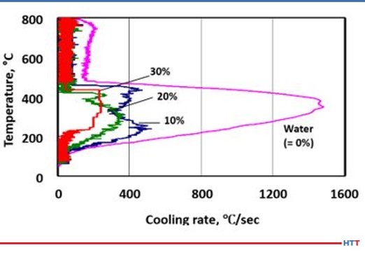
One of the unique properties a polyalkylene glycol possess that a quench oil does not is the ability to vary the cooling rate of the solution by concentration. Unlike an oil, a polyalkylene glycol solution is diluted with water and the amount of polymer to control the cooling rate varies with concentration. For instance, a 10% concentration of a polyalkylene glycol solution will have a faster and more severe quench rate compared to a 30% solution of the same polyalkylene glycol. Figure #4 shows a comparison of cooling speeds of various polyalkylene glycol solutions versus pure water.
Figure #4 The cooling rate of polyalkylene glycol solutions versus pure water.
2. The deterioration of a polyalkylene glycol polymer
While modern polyalkylene glycol quenchants are formulated to provide excellent corrosion and biological protection. The simple act of using them to quench parts creates conditions where the polymer deteriorates. As stated above, it the function polymer becomes inversely soluble at elevated temperatures and coat the parts to control cooling. This will also cause the depletion of the polymer and other additives through drag out. Similarly, as hot parts come into contact with the polymer, pyrolysis occurs. As a result of pumping, the polymer solution the polymer is mechanically sheared.
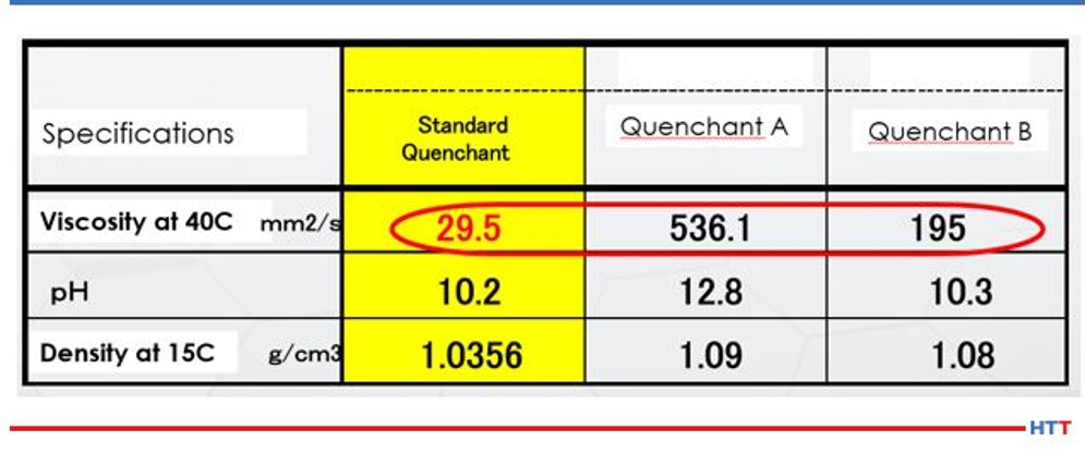
The solution undergoes mechanical shearing when a solution is continually circulated through a system by using a mechanical pump. The less viscous the fluid the less susceptible the fluid is to mechanical shearing. Table 2 shows the viscosity of three widely available commercial polyalkylene glycol polymers.
Viscosity and density of typical polyalkylene glycol polymers
Table 2 shows that Quenchant A is over 18 times greater than the viscosity of the viscosity of the standard quenchant, and Quenchant B is over 6 times the viscosity of the standard quenchant. Noting change in viscosity makes it is easy to see how mechanical shearing can affect polymers in different ways. As the solution is sheared and loses viscosity, the cooling properties of the polymer also change. Simple physics shows that the heat transfer properties of a thin, less viscous fluid, such as water, dissipates heat better than a thick, viscous fluid such as maple syrup.
In addition to mechanical shearing reducing the viscosity of the polymer, pyrolysis also creates a similar breakdown in the polymer. Pyrolysis is a chemical process where the polymer becomes thinner and less viscous due to the long chain length polymer being thermally broken into less viscous shorter chain polymers at high temperatures. Figure #5 shows the effects of mechanical shearing and pyrolysis on a short chain, less viscous standard quenchant polymer.
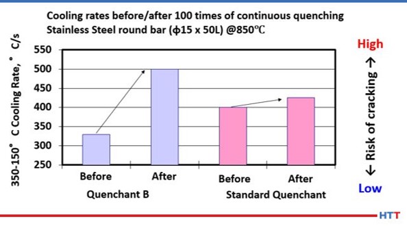
Figure #5 A depiction of viscous polymer subjected to pyrolysis after 100 quenches.
The severity of how pyrolysis and shearing affect the quench as the cooling speed of the polymer quenchant has clearly increased. This increase in the cooling speed is shown as the curve has shifted to the left. The increase in cooling speed and quench severity are directly related to the thinning polymer viscosity, which is directly attributable to mechanical shear and pyrolysis. To further emphasize this point, let’s look at how users of polyalkylene glycol quenchants determine concentration.
A handheld refractometer is typically used to measure what is often referred to as the refractometer reading. Some users and suppliers of polymer quenches instead use the proper term Brix%. The Brix% measures the amount of polymer dissolved in water and the contaminants within the polymer tank. Contaminants can be thought of as anything dissolved or emulsified in water. Several examples of dissolvable materials include hard water minerals such as calcium, or magnesium as well as any water soluble coolants or rust preventatives used in machining prior to heat treating. Some emulsified oils can be common machine oils, like hydraulic oil, that have leaked into the polymer tank.
Because all these dissolved or emulsified materials can impact the concentration levels of the polymer, most suppliers will ask for a periodic check of the solution be done using a benchtop refractometer. This reading measures how much light passing through a prism is refracted or bent by the polymer. Because the dissolved contaminants do not refract the light this is a more accurate method of determining the polymer concentration. However, it is a lab based piece of equipment and is not portable and must be liquid cooled to 20°C (68°F). Therefore, the portable Brix meter is typically preferred in heat treating operations.
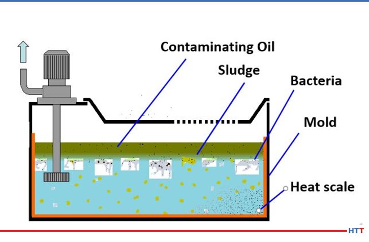
The most preventable form of deterioration of a polymer quench is from contamination by tramp oils, bacteria and in severe cases mold. Tramp oils are oils in the fluid that are not formulated into the quenchant. Because a polyalkylene glycol polymer does not contain oil any oil in the solution it is considered to be tramp oil. Regarding bacteria, there are two basic types: aerobic and anaerobic. Aerobic bacteria can live in the presence of oxygen and anaerobic bacteria thrive in oxygen depleted environments. The goal for users of polymer quench is not to eliminate bacteria entirely. This is because we do not live in a sterile environment. The water we drink, food we eat, and the air we breathe all contain bacteria. Instead, the goal of polymer quenchant suppliers and users is to prevent anaerobic bacteria and its “Monday morning odors.” Figure #6 shows a mockup of a typical sump containing a polymer quenchant and various contaminants.
Figure #6 Mockup of a Polymer Quenchant Sump
Above, the sludge layer consists of a mixture of tramp oil and polymer that has not gone back into solution. The most likely source of the tramp oil is from hydraulic oil or other machine oil leaks. This layer creates an impermeable layer against oxygen, leading to anaerobic bacterial growth. The tramp oil layer may be removed using an effective tramp oil skimmer. The anaerobic bacteria produce the rotten egg smell of hydrogen sulfide. The solution to eliminating the anaerobic bacteria is very simple. The removal of the tramp oil layer will allow oxygen to permeate through the solution through normal usage. However, removing the tramp oil layer is not enough. The second portion of the sludge layer is the polyalkylene glycol that emulsified with the tramp oil. Removing the tramp oil will cause this heavier than water polymer to sink to the bottom of the tank. This heavy polymer will prevent oxygen from reaching the material below the polymer once again creating a zone of anaerobic bacterial growth. The solution here is to use a shorter chain, less viscous polymer that will require less agitation to resolubilize in water at lower temperatures.
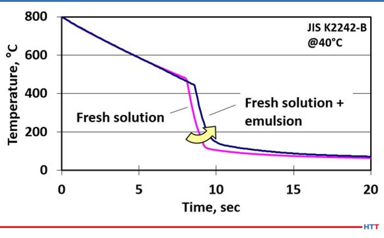
The effects on cooling speed are seen when a fresh solution of polymer quench is compared to the cooling speed of the same fresh polymer solution when a small amount of emulsified tramp oil and polymer is added to the same fresh polymer solution. This results in a shift of the cooling curve to the right, which slows the overall cooling speed and can result in lower case depth and softer than expected hardness results. The cooling curve is seen Figure #7.
Figure #7 These are the cooling curves of fresh polymer and fresh polymer mixed with tramp oil emulsion.
Another very common source of polymer deterioration is by contamination of heat scale which can easily be removed via filtration. Most individual induction hardening machines use an internal filter media bed. The micron size of these media filters can vary from the small ~2-3 micron to the large ~50 micron. For larger central systems and through hardening furnaces a canister filtration system is typically used. The micron size of the filtration media is typically an economic decision as the smaller pore size increases the cost of the filter. Also, the smaller the pore size the quicker the media will blind. A happy medium between cleanliness of the polymer solution and economics is typically found between 10- and 25-micron filter media.
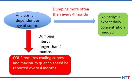
Figure #8 CQI-9 Flow Chart
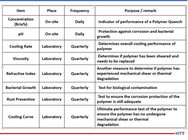
While CQI-9 requires only a daily concentration check and a cooling curve analysis for systems over four-months old, many suppliers of polymer quenchants recommend additional tests such as pH, viscosity, refractive index and other testing that is not practical for users of polymer quenchants to perform. Table #3 lists the test and frequency of the suggested test for a polymer quench solution.
Table #3 Suggested Tests and Frequencies for a Polymer Quench Solution
3. CQI-9 testing
This section will describe the testing required under CQI-9 as well as the frequencies and the reasons behind the suggested periodic tests.
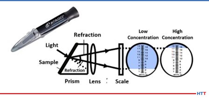
As mentioned earlier in this paper a daily concentration check is needed for a polymer solution. The most convenient and easiest method is to use a handheld refractometer. The operation of the handheld refractometer is seen in Figure #9.
Figure #9 Operation of a Handheld Refractometer
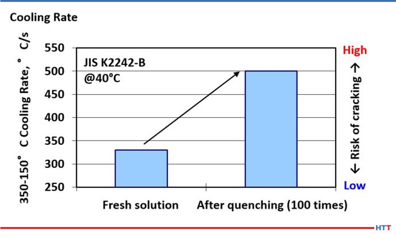
As previously noted, the mechanical shearing and effects of pyrolysis on a polymer are a reduction in the viscosity of the polymer in solution. Additionally, these same effects change the cooling properties of the polymer, as seen in Figure #6; the shifting of the cooling curve only describes the overall cooling curve of the polymer solution.
However, CQI-9 requires a cooling curve analysis. As a part of a compete cooling curve analysis, the cooling rate of the polymer should also be determined. Because there is a direct relationship between viscosity and cooling rate, it follows that as the effects of mechanical shearing and pyrolysis reduce the viscosity of the polymer in solution the cooling speed of the polymer will also increase as shown in Figure #101
Figure #10 Effects of Pyrolysis on Polymer Viscosity
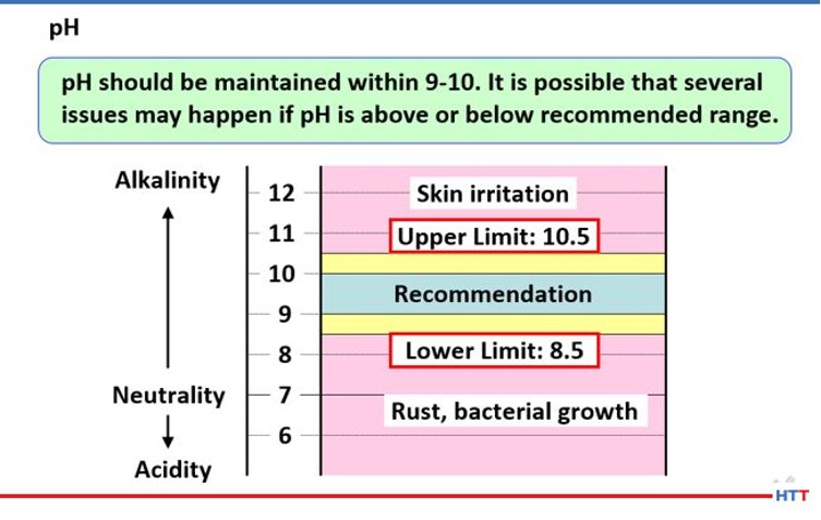
Knowing the pH of a solution is imperative for a few reasons. The higher the pH the higher the alkalinity and the better the protection against bacterial attack. Alkalinity is a measure of protection against corrosion. However, having too high of a pH can result in skin irritation. In Figure 11 below, the reader can see what pH manufacturers of polymer quenchants recommend.
Figure #11 Recommended pH Range
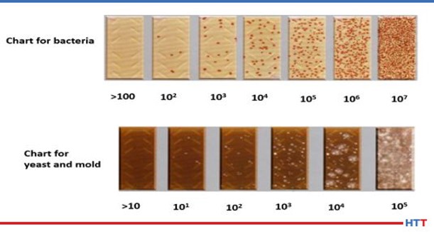
To run the bacterial testing on a polymer solution requires a special media called an agar to grow the bacteria colonies. These aerobic colonies are measured as a power of 10. Typically, these colonies are measured in the range of >100 to 10(7). In rare cases yeast and mold may also grow in a polymer quenchant. Once again, the colonies are measured in powers of 10. The typical range is >10 to 10(5). Figure #12 shows a pictogram of each level of bacterial and yeast and mold contamination. It is best to let the polymer supplier run this testing since it is dependent on sample handling and testing at a specified constant.
Figure #12 Agar Chart for Bacterial, Yeast, and Mold Testing
The last piece of maintenance to be addressed in this paper is the proper mixing of a polymer. Water should be added to the tank first. Once the water level reaches approximately ¾ of the full level, the water additions can end. The next step is to agitate the water while slowly adding in the polymer. It is important that the polymer not be added before the water as the polymer is much denser than the water. This will cause the water to remain on top of the polymer and will result in incomplete mixing. Once the polymer has been completely mixed into the water, a handheld refractometer can be used to determine the concentration, and then any needed water or polymer additions can be made.
Conclusion
This paper showed that the ability of a polyalkylene glycol to effectively quench and harden carbon steels is determined by a variety of factors:
Concentration
Polymer chain length
Viscosity of polymer
Mechanical shearing
Pyrolysis
Age of the polymer quenchant
The cooling speed of a polymer quenchant by concentration can be seen in Figure #4. The cooling speed varies by concentration because the amount of water present in the solution varies. The less dense water dissipates the heat faster than ticker denser polymer. Figure #13 shows the cooling curves of Quenchant A and the standard quenchant at concentrations of 10%, 20% and 30%. In Figure #13 the reader will notice less variation in the cooling curves for the standard quenchant compared to Quenchant A. This is due to the major differences in viscosity of the two products shown in Table #2.
Mechanical shearing will affect the cooling rate of a polymer by causing the viscosity of a thick polymer to thin out and become less viscous. Figure #14 shows how selecting a polymer with a polymer with a lower viscosity that is less resistant to mechanical shear and pyrolysis will exhibit less change in the cooling rate after continuous quenching.
Figure #13 Comparison of Colling Rates by Viscosity a After Continuous Quenching
Figure #14 Volume Savings Using Customer Data
In summary, a less viscous polymer is preferable due to the consistency of the quench, cooling speeds, and longer sump life than a more viscous polymer. Additionally, it will require less agitation to remix with water once the temperature of the solution is below the inverse solubility temperature of the polymer. Because the polymer remixes easily with water it does not plate out on the machines and fixtures and the carryout on the parts is greatly reduced. Since there is less plate out on the fixtures and machines along with the polymer remixing with water, there is a reduced need to dump the machine sump due to house cleaning issues. When the polymer goes back into solution, it does not settle to the bottom of the tank where it can create an environment for anaerobic bacteria growth as well. Figure #14 shows the annual volume reduction experienced when an actual customer switched to a lower viscosity polymer which resulted in a longer sump life and less drag out.
About the Authors: Greg Steiger is the sr. key account manager of Idemitsu Lubricants America. Previously, Steiger served in a variety of research and development, technical service, and sales marketing roles for Chemtool, Inc., Witco Chemical Corporation, D.A. Stuart, and Safety-Kleen. He obtained a BSc in chemistry from the University of Illinois at Chicago and is currently pursuing a master’s degree in materials engineering at Auburn University. He is also a member of ASM.
Keisuke Kuroda is the technical advisor for a line of industrial products which includes quench products for Idemitsu Lubricants America. Before joining Idemitsu in 2013, Keisuke held various sales and marketing positions. Keisuke holds a master’s degree in physics from Kobe University.
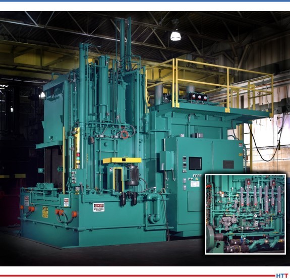
Considerable investment is made when purchasing a batch integral quench (BIQ) furnace. These popular furnaces need specific care and maintenance to keep them in prime operating condition. In this informative article by Ben Gasbarre, president of Industrial Furnace Systems at Gasbarre Thermal Processing Systems, learn how you can protect your BIQ from avoidable downtime.
This original content article appears in Heat TreatToday’s Air and Atmosphere’s February 2021 magazine. When the print edition is distributed, the full magazine will be accessible here.
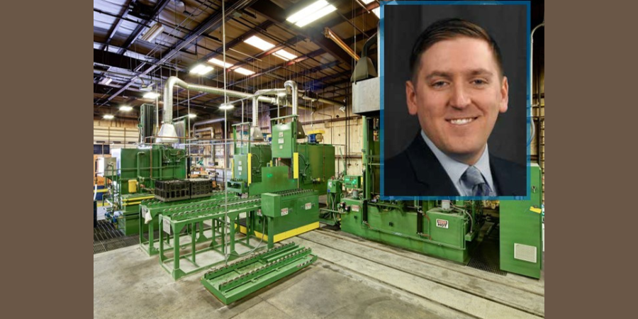
Ben Gasbarre President, Industrial Furnace Systems Gasbarre Thermal Processing Systems
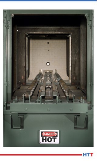
The batch integral quench furnace, or sealed quench furnace, is one of the most popular pieces of equipment in the heat treating industry. The core benefit is its versatility as it can easily adjust to changes in load weight, configurations, and heat treating processes. This makes
it a highly efficient and profitable piece of equipment for both captive and commercial heat treaters.
With all the good that is done in these furnaces, the downside comes in the maintenance of the equipment. By nature, these furnaces are hot, dirty, and have many moving parts, including multiple doors, load handlers, elevators, fans, quench agitators, and pumping systems; this furnace has it all! Although there are many areas of an integral quench furnace, understanding the subassemblies and having a good maintenance program can ensure the equipment operates safely and maintains its highest level of performance year after year.
Maintenance Safety
The discussion on maintenance of any piece of equipment begins and ends with safety. Prior to any work being done on the equipment, safety measures need to be considered based on the work being performed. Certain maintenance activities must be completed while the equipment is in operation; in these cases, proper personal protective equipment must be considered for work being done around hot surfaces, high voltages, elevated work, and potentially hazardous gases. If work is necessary while the equipment is offline, additional safety procedures must be followed, including lockout/tagout of all major power sources, special atmospheres, and natural gas supplies to the furnace.
Integral quench furnaces are considered confined spaces. Prior to entry into the quench vestibule, furnace chamber, and even quench pit, confined space procedures must be followed; hard stops must be in place for doors and elevators. Technicians need to ensure proper oxygen levels and air circulation prior to entry. The buddy system is always recommended when someone is entering the furnace. Prior to returning the furnace to operation, it is important to ensure all necessary safety and maintenance equipment has been removed, all supply lines are receiving designed gas pressures, and proper startup procedures are followed.
For furnace safety during shut down periods, it is wise to review furnace interlock systems and safeties to ensure proper operation. This includes items such as high-limit controllers, solenoid valves, burn off pilots, and other components critical to emergency situations. Additionally, per NFPA 86 requirements, valves and piping should be leak-checked periodically.
Reporting and Metrics for Optimum Performance
Image Source: Gasbarre Thermal Processing Systems
While Industry 4.0 is a popular concept in today’s manufacturing environment, the basic concepts behind the technology are what is important to any good maintenance plan. First, having an asset management system that enables engineers, operations, and maintenance personnel to access maintenance records is critical to ensure they can troubleshoot issues and perform maintenance activities more efficiently. Asset management tools are readily available and can range from well-established cloud-based software systems to simple Excel spreadsheet records. Ensuring important information, such as alloy replacements, burner tuning, or control calibration information, can help operations and maintenance personnel as they plan and assess future equipment needs.
The second concept is preventive or predictive maintenance plans. While these are not interchangeable concepts, the goal of implementing either is to reduce the likelihood of significant unplanned downtime, which can be costly to an organization. Preventive maintenance is a schedule of planned maintenance activities on a piece of equipment using best practices that give the best chance to catch a problem before it arises.
Predictive maintenance uses data and analytics from equipment operations that can be used to predict when problems are likely to occur. There are considerations for either approach, and the evaluation criteria for preventive versus predictive maintenance plans could be an article in and of itself.
Integral Quench Furnace Maintenance
As stated previously, breaking the furnace down into a series of subassemblies is the easiest way to develop an overall maintenance plan for equipment that has many sections and components. Discussed items will include mechanical assemblies, the heating system, the filtration system, atmosphere controls, temperature controls, and furnace seals. Each has its own importance to ensuring reliable equipment performance.
Mechanical Assemblies
Typical load transfer system alignment.
The mechanical system includes the load transfer system, recirculation fans, quench agitators, door assemblies, and elevator system. There are many exterior items that can cause abnormal equipment operation, including position sensors, rotary cam switches or encoders, and proximity switches, that if not operating properly can interrupt or cause failure within the furnace. Position settings should be logged for future reference, and sensors should be inspected regularly. Belts that may be used on recirculation fans and quench agitators should be inspected regularly for damage and excessive wear. Vibration of these items should be monitored as excess vibration can be an indication of damage or wear to the fan or agitator bearings, shaft, or blades.
The largest item of concern in this system is the alignment of the load transfer system. Unsuccessful load transfer due to misalignment or obstruction can cause significant furnace damage and create unsafe conditions within the furnace. Internal alloy components should be evaluated for integrity and alignment every six to twelve months. Elevator alignment should be reviewed to ensure smooth operation during the same period. Frequent visual inspection through sight glasses, quench time monitoring, and motor load data can give valuable information of future potential transfer issues within the furnace.
Heating Systems
Whether your furnace is gas or electrically heated, well-maintained systems can have significant impact on the operating efficiency of a furnace. For gas-heated systems, proper burner tuning and combustion blower filter cleaning can ensure optimum gas usage and can also improve radiant tube life. Burners, pilots, and flame curtains should be cleaned at least once or twice a year to ensure proper performance.
Electrically heated systems typically require less general maintenance and have fewer components that are susceptible to failure. Regular checks of heating element connections and electrical current resistance can help to identify upcoming element failure.
The largest and most critical components of reliable process performance are the radiant tubes. A crack or leak in a radiant tube can cause part quality issues. Changes in your furnace atmosphere gas consumption or troubles from controlling carbon potential can be signs of tube leaks. If the radiant tube failure is unexpected, it can also cause significant downtime if replacement tubes are not available. Cycle logs and run hour timers are the best metrics for preventive or predictive maintenance on radiant tubes.
Filtration Systems
Filtration systems are recommended for most integral quench applications. They help to eliminate build up and contamination in the oil recirculation system that flows through the heat exchanger and top/atmosphere cooler on the furnace quench vestibule. Filtration systems typically are comprised of a pump, dual filters, and an alarm system to alert users when it is time to change filters. Maintenance on your quench oil can vary by composition. Quarterly analysis of the quench oil performance is common. However, it is recommended to consult with your quench oil supplier to ensure safe and effective performance.
Atmosphere Controls
Integral quench furnace atmosphere systems can vary both by manufacturer and in overall gas composition. The most common being endothermic gas, nitrogen/methanol, along with options for ammonia or other process gases. Although these items may vary, maintenance remains consistent. Users need to ensure the integrity of the piping system including regulators, solenoid valves, and safety switches.
Endothermic gas lines should be cleaned out at least once or twice a year. Many furnace atmosphere problems can be traced back to endothermic gas generator issues, so it is important to have a well-maintained atmosphere generator to ensure peak performance in your integral quench furnace.
Typical integral quench furnace atmosphere system.
Recent technology allows for automatic burn-off of carbon probes and automated atmosphere sampling. However, probes should be burned off once per week if they are manual. Probes will require calibration and periodic replacement, and they can be rebuilt to like-new specifications. Controllers or gas analyzers that support carbon potential control should be calibrated quarterly, biannually, or annually depending on heat treat specification requirements.
Updates in the automotive CQI-9 specification will require calibration of all atmosphere flowmeters on a periodic basis. Users will need to be aware of this requirement and understand how their gas flowmeters should be calibrated. In some cases, control upgrades may be required.
Temperature Controls
Temperature control maintenance typically follows AMS2750 or CQI-9 specifications. This would relate to thermocouple replacement, system accuracy test procedures, and controller calibrations. Depending on the age of the equipment and specification requirement, these items may need to be done as frequently as once per quarter or annually.
Temperature uniformity surveys (TUS) follow similar specifications for frequency. However, a TUS can diagnose areas of the furnace that may need maintenance attention. Having a baseline TUS to reference will help identify changes in furnace performance. Changes to a TUS can indicate burner or element tuning requirements, an inner door leak, refractory damage, fan wear, or radiant tube failure.
Furnace Seals
Integral quench furnace seals can be a source of heartache for any maintenance technicians working to troubleshoot a furnace. Typical seal areas include the inner door cylinder rod, elevator cylinder rods, inner door seal against furnace refractory, outer door seal against quench vestibule, fan shaft(s), and an elevator seal if there is a top atmosphere cooler.
Typical sealing of cylinder shafts are glands comprised of refractory rope and grease. Greasing of these areas should be completed weekly. Outer door and elevator seals are typically fiber rope and may have adjustment built in as they wear, but ultimately will need to be replaced. Frequent inspection of these areas will help identify early issues. Using a flame wand or gas sniffer can help find leaks in unwanted locations. Small furnace leaks can cause part quality issues, and larger leaks can also create safety concerns within the furnace.
Additional Maintenance Items
Other key maintenance items include a bi-monthly or monthly burn out of the furnace heating chamber. This requires the furnace to have air safely injected into the chamber at or slightly above process temperature to allow the carbon to burn out of the furnace. Doing this process on a regular basis will help improve refractory and alloy component life as well as helping to maintain good process control.
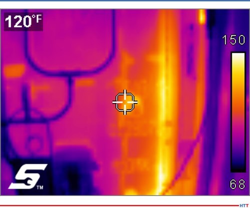
Example thermal camera image
Another helpful snapshot of furnace health is using a thermal camera to take images of the equipment. It is recommended to do this on a monthly or quarterly basis. Thermal camera images can identify hot spots on the furnace outer steel shell that may indicate refractory deterioration or a furnace atmosphere leak. Thermal images can also identify potential issues with motors or bearings on fans and agitator assemblies.
Conclusion
In the end, all furnaces have different nuances that require different maintenance approaches. This could be based on the manufacturer, types of processes being run, or utilization of the equipment. By consulting with your original equipment manufacturer or other furnace service providers, a strong maintenance plan can be developed and implemented. This can include support and training from experienced professionals on that style of furnace. Broader cost benefit analysis should be done as it relates to spare part inventories, resource allocations, frequency of preventive maintenance activities, or investments into predictive maintenance and asset management technologies and how those activities can maximize utilization of each piece of equipment.
About the Author: Ben Gasbarre is president of Gasbarre’s Industrial Furnace Systems division. Ben has been involved in the sales, engineering, and manufacturing of thermal processing equipment for 13 years. Gasbarre provides thermal processing equipment solutions for both atmosphere and vacuum furnace applications, as well as associated auxiliary equipment, and aftermarket parts and service.
All images provided by Gasbarre Thermal Processing Systems.
What do gas nitriding, hot isostatic pressing (HIPing), black oxide coating, and high pressure gas quenching have in common? They all are key processes in heat treating firearm components.
Written by Rob Simons, manager of metallurgical engineering at Paulo, this in-depth Original Content article covers Paulo’s perspective on the thermal processing of firearms components and best practices for handling and lot traceability.
Check out more of Heat Treat Today’sTechnical Tuesday articles by searching “technical tuesday” in the search bar.
Rob Simons Manager of Metallurgical Engineering Paulo
While many industries are continuing to reel from the ongoing coronavirus pandemic, the firearms industry in the United States is booming. Over the past decade, the sector’s strong growth has only accelerated in 2020, fueled by consumers’ response to the pandemic and ongoing civil unrest. According to the NSSF’s 2020 Firearm and Ammunition Industry Economic Impact report, the firearms industry is responsible for well over 300,000 American jobs—a figure that has doubled since 2008.
Consumer demand for firearms also drives the need for heat treatment services for this highly regulated industry. Proper thermal processing is critical for safety and also plays a key role in delivering the quality finish that manufacturers want and consumers expect. In this article, we’ll share our firearms heat treatment expertise, delving into the common processes, specifications, and considerations of servicing this thriving industry.
Key Heat Treatment Processes for Firearms Components
Gas Nitriding
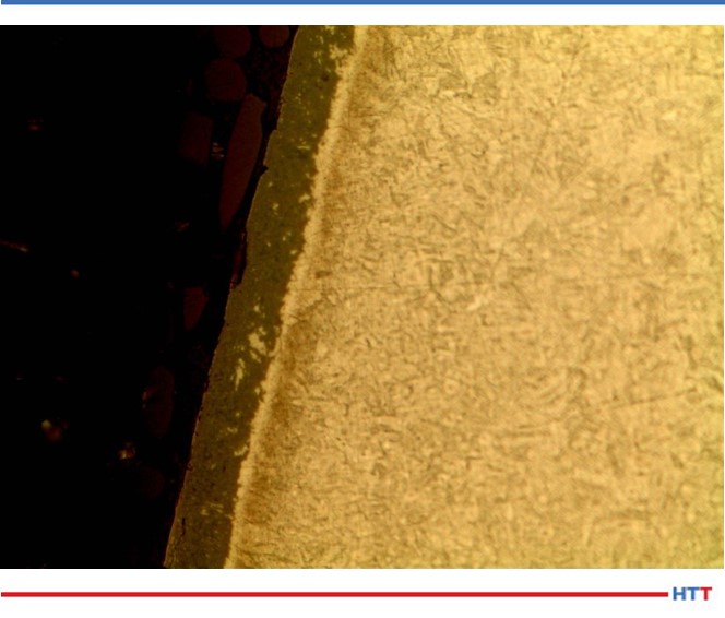
Nitrided 17-4.
Gas nitriding is used to case harden parts that must retain softer, more ductile cores. Because it is carried out at a lower temperature, gas nitriding helps prevent the part distortion that can sometimes occur as a result of conventional heat treatment. In addition to hardness characteristics, parts are often nitride coated for cosmetic purposes and to enhance corrosion resistance. Nitriding results in a beautiful, highly durable black coating that is often used in place of black oxide coatings or other blackening processes. Nitride coating is much harder than the alternatives, so the black finish will stand up to heavy use significantly longer.
Components and Materials Commonly Treated With Nitride Coating
Nitride coating is typically performed on outwardly visible components (and those you’d see while cleaning the gun) such as handgun slides and barrels, as well as muzzle devices such as flash hiders, muzzle breaks, and compensators.
These components are usually manufactured using the following materials, which can be nitrided to achieve the desired black finish and case hardness:
4140 steel. AISI 4140 is a chromium-, molybdenum-, and manganese-containing low alloy steel (usually referred to as chrome-moly steel). It has high fatigue strength, abrasion and impact resistance, toughness, and torsional strength.[1]
Grade 416 stainless steel. Grade 416 steel is a free-machining, martensitic stainless steel with a machinability of 85%. [2]
Grade 410 stainless steel. Grade 410 stainless steels are general-purpose martensitic stainless steels containing 11.5% chromium. Grade 410 steels have good corrosion resistance properties which can be further enhanced by hardening, tempering, and polishing.[3]
Grade 420 stainless steel. Grade 420 stainless steel is higher incarbon than 410 with a minimum chromium content of 12%.
4340 steel. AISI 4340 alloy steel is a low alloy steel containing chromium, nickel, and molybdenum. When heat-treated, it exhibits high toughness and strength. This material is considered extreme duty and is typically used for higher-end firearms.[4]
17-4 stainless steel. 17-4 stainless steel is an age-hardening martensitic alloy combining high strength with the corrosion resistance of stainless steel. It is relatively cost-effective and more weldable than other martensitic alloys.[5]
Nitriding Specifications
The most common measurement that firearms manufacturers specify in desirable nitriding results is intermetallic depth. Typical specifications fall between four and 25 microns of white layer depth. The amount of allowable porosity within the case depth is also commonly specified, and while there are varying ranges, less than 50% porosity is a typical target.
While porosity is often regarded as an undesirable characteristic, there are advantages to some porosity in the finished material. These microscopic voids can hold oils and enhance corrosion resistance. The resulting porosity in nitrided materials allows the coating to last dramatically longer than phosphate- or black-oxide-coated steels.
Some manufacturers utilize blanket aerospace specifications such as AMS 2757 or AMS 2959/12 because they encompass the desired porosity and case hardness depth for nitrided firearms components.
Vickers hardness testing is our preferred method for evaluating intermetallic depth in nitrided components. While 850 HV is typically the top achievable hardness for stainless steel, our team has consistently achieved 2000 HV with our nitriding processes. Higher-end hardness is beneficial for firearms components because it enhances wear resistance in components that slide against each other.
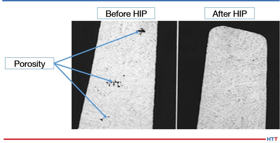
Casting of unknown material showing consolidation of macro pores through HIP.
Hot Isostatic Pressing (HIP)
With hot isostatic pressing, parts are heated to very high temperatures in a sealed chamber capable of generating very high pressures in the presence of inert gas. During processing, heat and pressure combine to close the voids that formed during part manufacturing, eliminating weakness in the parts. Most firearms components respond well to standard coach cycles for HIP, which commonly run at 2050–2200°F and 15,000 psi.
Firearms Components and Materials Commonly Processed With HIP
HIP is especially well suited for removing porosity from metal injection molded (MIM), additively manufactured (AM), and investment cast parts.
MIM is a fast, cost effective way to produce fire control components such as hammers, triggers, and safety selectors, especially for AR-15’s. Traditionally, MIM components have had a reputation in the industry for being inferior to those manufactured with conventional machining because they have been known to fail early in the field.
Common MIM grades used in the manufacturing of firearms include 4140 steel, 17-4 stainless steel, and…
FL-4605. FL-4605 is a low alloy steel with prealloyed manganese, molybdenum and nickel content for enhanced hardenability.[6]
420 stainless steel. 420 stainless steel is relatively high in carbon with a minimum chromium content of 12%, which gives it the highest hardenability of stainless steel grades.[7]
Additive manufacturing has not yet been widely adopted in the firearms industry, but we have seen it increasingly used in the manufacture of suppressors. These components—commonly known as silencers—trap the expanding gas as the weapon is fired to reduce noise, and are used for military sniper rifles. AM is an ideal method of manufacture for these components due to their complex geometry that is difficult or even impossible to achieve with traditional machining.
Investment casting is another process we see used in the production of handgun frames, specifically in the M1911 pistol.
MIM, AM, and investment castings all have one thing in common: these manufacturing methods leave voids behind in the internal structure of parts. HIP eliminates unwanted porosity in these parts, increasing their toughness, gross strength, and fatigue life which allows firearms components to withstand being repeatedly subjected to high impact.
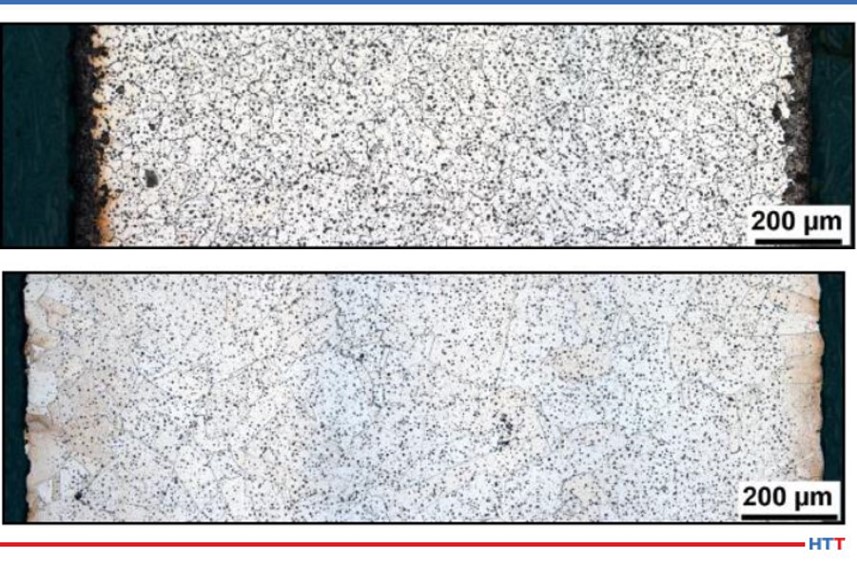
MIM 316L before (top) and after (bottom) HIP. Porosity has been consolidated, but there are solid inclusions in the material.
HIP Specifications
For additive manufactured firearms components, we encounter two primary specifications:
ASTM F3301, a specification that outlines standards for thermal post-processing for metal parts made with powder bed fusion. ASTM F3301 identifies hot isostatic pressing as an acceptable means to stress relieve additive manufactured components.
ASTM F3055, the standard specification for additive manufacturing nickel alloy with powder bed fusion. In this specification, HIP is required for Class B, C and D components and is considered optional for Class G.
In both specifications, components must be processed under inert atmosphere at no less than 100 MPa within the range of 2048 to 2165°F (1120 to 1185°C). Parts must be held at the selected temperature within ∓27°F (15°C) for 240 min ∓60 min, and cooled under inert atmosphere to below 797°F (425°C), or to parameters as agreed upon between the component supplier and purchaser.
Black Oxide Coating
Black oxide gives firearms a sharp black appearance, enhances corrosion resistance, and minimizes light reflection. Unlike paint, black oxide doesn’t add any additional thickness to gun components. The desired result in the black oxide process is creating magnetite (Fe3O4), an alloy of iron and oxygen, on the surface of the metal. The black oxide process enhances corrosion resistance by adding rust preventive oils to the metal part.
While it doesn’t last as long as gas nitride coating, black oxide is still a popular, cost-effective option to give visible gun parts the perfect black look. Finding a partner that can provide heat treatment and black oxide under one roof can reduce your transportation costs, speed up turnaround time, and simplify your overall process since one supplier owns the final results.
Firearms Components and Materials That Use Black Oxide Coating
Like nitriding, black oxide coating is used on outwardly visible components like slides, barrels, and muzzle devices including flash hiders, muzzle breaks, and compensators. It can be applied to any carbon steel component, but it will not adhere to stainless steel.
Specifications for Black Oxide Coating
Unlike nitriding and HIP, we rarely encounter standard specifications when it comes to black oxide results. However, as a best practice we work with customers to establish boundary samples for each part number treated with black oxide so we can compare our results to what both sides agreed upon as a desirable appearance.
High Pressure Gas Quenching
High pressure gas quenching can be performed in a vacuum furnace as an alternative to oil quenching for any firearms components that are near net shape or completely finished—or where distortion is a chief concern. In high pressure gas quenching, parts are austenitized under vacuum. Then, the chamber is backfilled with inert gas, which is heavily agitated by powerful motors.
High pressure gas quenching results in cleaner parts than oil quenching, but it has other benefits that can prove highly valuable for firearms components. This process can take a conventional 4140 alloy and make it achieve the same properties as a vacuum arc remelted (VAR) 4340, a much higher quality nickel-based material. This can allow firearms manufacturers to see similar hardness and strength results in everyday components as those they would expect from an extreme duty material like 4340.
Handling and Traceability for Firearms Components
No heat treater should make a habit of losing any type of parts, but the implications for serialized firearms components are more severe than any other mass-produced components. Serialized components are what the U.S. government considers the firearm—it refers to the part that features the serial number, usually the lower frame assembly and sometimes the barrel or slide.
Firearms components to be treated with gas nitriding that have AMS 2757 or AMS 2759/12 identified as the standard are also subject to the recordkeeping guidelines outlined in the specification. AMS 2757 requires that documentation includes the equipment and approved personnel’s identification, date of processing, number of parts, alloy, lot identification, and actual thermal processing times and temperatures at a minimum.
Proper handling of firearms components by heat treaters is essential to keep the supply chain running smoothly. Improperly heat treated parts will either wind up in the scrap bin or require reprocessing, and lost parts can result in an ATF audit or investigation. At our company, we’ve engineered our process to prevent issues from occurring in the first place. Here are a few examples of how we do it:
Electronic tracking. Each lot of parts is assigned a barcode that links to electronic records of all relevant information about the job—process parameters, specifications, shop orders, etc. The process parameters on the parts’ barcode are integrated with equipment, so when parts are scanned for processing, the furnace will be automatically set to the proper parameters according to the parts’ recipe. This helps us prevent parts from being improperly heated or subject to the wrong process altogether.
Secure storage. In Paulo plants that process firearms, we use locked cages and secure vaults to protect serialized components. All access to these areas is monitored and recorded to maintain accountability and, if applicable, adhere to AMS specifications.
Specialized handling. To give our firearms customers more peace of mind and to safeguard against errors in our process, we’ve also engineered secure fixturing for many components that allows them to remain locked throughout the entire heat treatment and finishing process.
In addition to a Federal Firearms License (FFL), heat treaters should also have a documented quality management system in place. Choosing an ISO 9001-certified supplier can help give manufacturers confidence in a heat treating partner’s ability to maintain quality operations. Maintaining other certifications such as IATF 16946 and CQI-9 is also a good sign that your partner is well equipped to handle firearms work.
Conclusion
The firearms industry relies on its thermal processing partners to sustain its growth. Proper heat treatment and metal finishing results in better performing, longer lasting firearms for our military and law enforcement, which helps keep our country safe. In uncertain times, the firearms industry represents a bright spot in the U.S. economy that we are proud to support.
About the Author: Rob Simons is manager of metallurgical engineering at Paulo where he leads the commercial heat treating industry’s largest in-house metallurgy team. Rob continuously spearheads research and innovation at Paulo that lead to advanced capabilities and better results for the company’s customers. Rob holds a bachelor’s degree in Metallurgical Engineering from the Missouri University of Science & Technology.
About Paulo: Founded in 1943, Paulo is one of the largest providers of thermal processing and metal finishing solutions in North America. Headquartered in St. Louis, Paulo operates six divisions servicing the United States and northern Mexico.
In this episode, Heat TreatRadio host Doug Glenn talks with Joe Powell of Integrated Heat Treating Solutions in this fourth and final episode about bringing heat treating into the 21st century. This episode covers Direct from Forge Intensive Quenching – forge shops, listen up!
You are about to listen to the 4th and final episode in a series on rethinking heat treatment, with Joe Powell, of Integrated Heat Treating Solutions. You can find the previous episodes at www.heattreattoday.com/radio.
Below, you can either listen to the podcast by clicking on the audio play button, or you can read an edited version of the transcript.
The following transcript has been edited for your reading enjoyment.
DG: Joe, if you don't mind, take us on a 30,000 foot overview of what you've been doing at Integrated Heat Treating Solutions.
JP: What we've been doing for the past 23 years at Integrated Heat Treating Solutions and the last 75 years at Akron Steel Treating is applying heat treatments to parts made by others. We had over 1200 customers on our customer list at Akron Steel Treating and they use various materials. We kind of grew up in the shadow of the Cleveland market, which is the largest market for heat treaters, and there is the largest number of commercial heat treaters in the Cleveland market. This was possibly outnumbered by Detroit at one time, but I still think that we're probably the number one market for heat treating in this part of the country.
What has happened over the last century, in the 20th century, is that heat treating has become very, very good. New equipment has been developed like controls, thermocouples, oxygen probes, vacuum furnaces, vacuum quenching, high pressure vacuum quenching, oil skimmers, new quenchants made with reverse solubility polymers - all of these things have come together and made heat treating very, very good. However, as part of that, there has been a commoditization of heat treatment. That means that heat treating became so good that parts rarely crack or distort unacceptably, and companies have devised methods for correcting the distortion through hard turning, grinding, straightening, flattening, you name it. And the part makers and the heat treaters got along, in a kind of peaceful coalition, to get the parts out the door to the end user.
However, in the 21st century, that is just not good enough. In lean manufacturing, you have to offer an integrated solution for what you're doing. The entire value chain for making a product has to be on the same page; they have to be in alignment. The processes have to be in the proper order. What we're trying to do with Integrated Heat Treating Solutions is bring the last dimension of part design, what we call the Z dimension, to the part makers, their designers, and their material suppliers, so that we present a solution that delivers the optimal amount of value and eliminates the waste from heat treatment, or forging, as we'll talk about today.
[1] Defense Logistics Agency, "About," https://www.dla.mil/AboutDLA/ [2] DFIQ FIA Technical Committee Presentation, "Evaluation of Intensive Quenching Hardening Process Immediately After Completion of Hot Forging Operations," 2018. [3] Forging Process Improvement Using Intensive Quench, 2019.DG: Right. In these four episodes we've been talking to people about bringing heat treating into the 21st century. On your website, integratedheattreatingsolutions.com, there is a good illustration table that shows what heat treating was like in the 20th century and what it is like in the 21st century. That's basically what we're talking about. Just a quick recap of the previous three podcasts we've done: It all revolves around a customized heating, but more importantly, a customized quenching of materials so that the distortion of those parts is predictable, and that the part design can be altered so that there is essentially no post heat treatment processing. In other words, you can pretty much eliminate grinding or any type of machining, straightening, and that type of thing. Once heat treated and quenched with the technologies that you're talking about, the part is essentially pack and go.
We've talked about several examples, but the two we talked about in the recent podcasts were an 18” bevel gear, which was quite interesting. Then we talked about a fracking pump valve seat, which was also quenched in this way. So today, you and I want to talk about, as you alluded to, the forging industry. We're going to talk about something called (direct from the) forge intensive quenching (DFIQ). If you don't mind, tell us what that is. For those people in the forging industry, what is direct from forge intensive quenching?
JP: It's the principle that the forging processes use a lot of BTUs of heat to heat up a billet, and then bang it into a shape and get the grain flow going in the direction that will be great for the part mechanical properties. Once that forged shape is attained and the grain flow is attained, the part is usually allowed to cool at the end of the forging trim die line, and those cooling forgings will all cool at different rates. Because they cool at different rates, you have some fast cooling on the surface, the corners and the thin sections; but you have some very slow cooling in the core. At the end of the day, the part needs to be heated a second time in a normalization process, which heats the part to a high temperature and then does a controlled cooling of the part to align the grains of the part and the size of the grains to remove the kind of mishmash of structure that is present in an as-forged part. Then, if the part is going to be hardened at some point, and usually there is a lot of rough machining that goes on to remove the scale from the forging process, machining is necessary to remove the scale from the steel mill that has basically been hammered into the surface of the forging. All of that rough machining is done to basically present a rough machine part that can then be heat treated. So, companies like Akron Steel Treating or the captive heat treats at the forging plants will then heat the part a third time to the austenitizing temperature. If the part is made out of a martensitic steel, they'll quench it, usually in oil or polymer, and then possibly temper it to stabilize the part, and present it to the part maker for final machining, grinding and whatever final processing needs to be done to turn that forging into a useful part with the desired mechanical properties.
Akron Steel Treating doesn't do a lot of forged heat treat. We do some aerospace parts for braking systems for airplanes, called torque tubes, which is basically the hub of the braking system. Those torque tubes are generally made out of forgings which we see after forging, and then see again after 50% of the material is removed. Then the part is heat treated. In those instances, direct from the forge intensive quenching is not going to work.
Direct from the Forge Intensive Quenching
This direct from the forge intensive quench (DFIQ) project came out of a desire by the Forging Industry Association (FIA), which incidentally Akron Steel Treating has been a member since 2012. We've always felt that we could create more streamlined processing as well as a better part with leaner material if we worked together with the forgers and integrated the heat treat process with the forging process. Companies like the TimkenSteel Company have come out with low alloy materials that are forged all the time, and then they do a controlled cooling where they'll actually air cool the forging. With the alloying elements that are in there, they are able to come up with mechanical properties directly from the forge after a controlled air cool. No normalization is needed and no further austenization, or third heating, is needed. Basically, the part is air quenched and tempered right there in a controlled manner from the hot forge.
Some folks in India and Japan have tried several times to do direct from the forge liquid quenching using oils directly from the forge. What they found is that the oil quench catches on fire, and if they can keep it from catching on fire by enclosing the quench under an inert atmosphere, they're still going to have the problem of the very high heat, like 2000°-2200° F, creating a steam blanket of hot oil, or in the case of polymer water, a steam blanket of polymer water mix around the outside of the part. This then produces an inability to uniformly quench the part because the thin sections will very quickly quench out, the thick sections will sit there under a blanket of gas and essentially those two mixes of nucleat boiling - very fast evaporative cooling in the thin sections and a full-blown gas blanket on the thick sections - create a nonuniform shell around the outside of the forging. As that part cools under that nonuniform shell, it is also going to thermally shrink in a nonuniform way. Also, when it cools to the martensite start temperature, it's going to start transformation and face change in a nonuniform way in that shell.
The successes of direct from the forge quenching didn't happen until this project we started in 2015 with the Defense Logistics Agency (DLA), which “manages the global supply chain – from raw materials to end user to disposition – for the Army, Marine Corps, Navy, Air Force, Space Force, Coast Guard, 11 combatant commands, other federal agencies, and partner and allied nations,”and the FIA tech committee members who sat down and asked: “Do you think we can do this in water?” If we can do it in water, we obviously eliminate the fire hazard, but how do we eliminate the boiling hazard, or the boiling issue in the nonuniformity? And that's where we had, at that time, 15 years of experience in applying the intensive quenching process or intensive quench process.
Luckily, John Tirpak, who was then working with the DLA and the FIA as a technical advisor, saw the benefit in giving it a try. We had done lots of parts that people had said, over the years both at Akron Steel Treating and Euclid Heat Treating, couldn’t be done. And we did it. We applied it in the case of the valve seat to ductile iron to replace an 8620 carburized seat. So, we have this great flexibility, we have this great new tool, we just need to use it, or at least try it, at the forge. And that's what the DLA funded. They basically gave us a budget for the building of a prototype unit which was built and is pictured in the final report It shows the test parts that were actually quenched directly from the forge at Bula Forge in Cleveland, and then we moved the prototype unit next to Welland Forge in Canada and finally to Clifford-Jacobs Forge in Illinois.
The upshot of all of this was that once we figured out that if we could remove the film boiling from the outside of the hot forging, we could basically set the shell, and once the shell is set, we get, on most parts and most geometries, a martensite shell that is formed. That martensite shell continues to form down into the layers of the onion below the surface as the martensite temperature is reached and that martensite transformation continues by conduction, very uniformly through the mass of the part. What you end up with is a part that comes out of the quench pretty much like it went through a normalization process and then a third reheating and an oil quench and a temper. We get some self-tempering as well because we interrupt the intensive water quench before the part is fully cooled. Nonetheless, we found in the first phase of testing that parts should be tempered in a tempering furnace to develop the full effects of the tempering process, so that process is still done after the parts come out of the quench. But you eliminate the normalization process and the third reheating for an oil quench and temper that would normally be required.
Examples of DFIQ equipment (Photo source: Joe Powell)
DG: Can you tell us what parts were actually run?
JP: Yes, there were a variety of parts, and they're all pictured in that report. They ranged from a link that weighed, I believe, close to 50 pounds all the way down to a tine that was on a tiller machine (ground engaging tool) that went into a piece of farming equipment. One of the parts in between was a pintle adapter that was basically a mounting post for a machine gun for the Army. This part went through several operations. It's documented in the report, but we basically saved $13 per part to the Army by eliminating the multiple steps that took place after forging and just incorporated it into an integrated heat treating solution right there at the trim die.
DG: How did that look? Let's take the tine, for example. It's stamped out on a forge press. You've got a hot piece of metal put on a forge press stamped out. Then, one at a time, these parts are taken off of the forge press and immediately put in a quench?
JP: After they come out of the trim die, they're still pretty hot - they're still austenitic, and range in temperature from like 1900°F all the way up to 2200°F - and then they go directly into the quench. 15-45 seconds later another one comes out of the trim die and goes down into the shoot and up the conveyor and into a box to await tempering. We time the conveyor so that the dwell time in the intensive water quench is properly timed so that the core still has enough heat to self-temper, but not too hot that it over tempers the part.
DG: I'm curious about the part. After the part comes off the trim die, is it manipulated? Is there a manipulating hand that comes in and grabs it, takes it off, puts in the quench tank?
JP: In the case of the prototype, the manipulating hand was the forger. He came with tongs and provided a very 19th century placement of that part. But, obviously, all of this stuff can be automated and integrated, and with the proper equipment can be done in a way that is seamless from the time the billet is heated all the way through.
DG: Tell me this, that tine again, when the guy took it off the trim die, did he just throw it in an intensive quench tank or was it fixtured?
JP: Picture an elevator platform. It was placed on an elevator and then the elevator went down between two panels that presented water at very high flow to the part and knocked off the film boiling. I should add, the tine was the thinnest part and the enthusiasm at Clifford-Jacobs was very, very high because once they figured out that this worked, the guys on the floor said, “Let's try this part, let's try that part, let's try this part.” And of course, in the first test at Bula Forge, we actually tested at least four different alloy materials and so all of those variables would have to be integrated into the design. I call it the Z dimension of the design. You pick the right material, you have the right forging temperature of the billet, and you don't overheat it. One of the lessons learned in the four-year study is that if you overheat the forging to “help with die life” - that overheating of the forging to 2400°F (almost to the melting point) - the grains blow up. No amount of intensive quenching is going to bring them back. So, you've got to keep the temperature around 2150°F; that's about the maximum in Fahrenheit.
All I can say is that if you maintain a forging temperature uniformly around 2150°F in the billet, we can devise a quenching system that will blow the film boiling off and set that shell in the part in all but the thinnest parts in the prototype. We did about 150 tines in a row with the protype, and then the water heated up because we only had so much chilling capacity in the water tank. But as the water heated up, the quench wasn't as effective, and the tines actually exhibited some cracks when we ran another 150 - that's because there was film boiling in the mounting holes. The lesson learned was you have to have a flow, but you also have to have some pressure in order to instantly impact that part. That instant impact is key in the proprietary processes that Integrated Heat Treating Solutions is developing to bring the next version of the DFIQ unit to make it able to do the thinner parts without cracking.
DG: DFIQ, of course, standing for direct from forge intensive quench.
You've referred to a study multiple times and that study is a 2019 study called,Forging Process Improvement Using Intensive Quench. It looks like that was, as you mentioned, funded by the DLA in either 2014 or 2015. We will make that report available and people can take a look at it. Anyone that is a forger in a forge shop, or a captive forge would certainly want to take a look at that. Would forge press companies be interested in this? Could they build quenches into the actual press itself so that this process could be, more or less, in line?
JP: Yes, absolutely. Again, it is a different paradigm for them. Just like I mentioned before, all the heat treating equipment makers call themselves furnace companies and all the forging equipment makers call themselves press makers or forging die makers. The reality is the process continues and the mechanical properties in the setting of those grain flows happen in the heat treating process; the refinement of those grains happens in the heat treating process which happens in the quenching process. So, again, we need to integrate that quench into the forming equipment. Again, I have no intention, as Integrated Heat Treating Solutions or Akron Steel Treating, of getting into the business of building systems- that's not my thing. My thing is to develop a robust process that can be applied and implemented using automation and new equipment with the proper pumps and material handling that is all integrated into a seamless process.
DG: Let's talk very briefly about the benefits. We've already alluded to quite a few of them, but let's try to enumerate them here. What are the benefits to a captive forge shop in considering a DFIQ type system- why do it? What's the commercial value?
JP: We can save up to 66% of the energy that's needed to heat treat that part. The part comes off the trim die and is cooled in a box or set aside somewhere. Next, it needs to be reheated and normalized. Then, it has to be reheated a third time and austenitized before quench and temper, and that's a lot of energy. And it's also not usually done at the forge plant. It's usually done either at a captive heat treat that is integrated with the forging company or it goes to a commercial heat treat where they use huge continuous furnaces to reheat the parts and quench and temper them. I'm not going to make a lot of friends in the areas that do this, but if we're going to compete in the world and make great parts, be lean, save energy, and also have safe carbon emissions, we've got to stop heating parts that don't need to be reheated if you can avoid it. I'm not going to claim that it works on each and every part and that it should be used for each and every part. I'm just saying that there's a lot of parts that could be made a lot more efficiently if we would quench them right at the trim die.
DG: So, one of the benefits you just mentioned is potentially saving 66%, basically two-thirds, because you don't have to do a second and third heat. What else do we have?
JP: What you can have is better uniformity of mechanical properties. You can also elicit more hardenability out of a particular alloy by having this higher ability to harden with a very, very fast quench. That intensity of quench locks in mechanical properties that are unattainable in a typical oil quench or polymer water quench. One example of that is a forging that we do for a company, in fact it was one of the companies in the study. It's a 44” gear rack- it's 44 inches long, about 5 inches wide and about 4 inches thick. This gear rack is used as a piece of mining equipment and actually 10 of them are used on each side of a tower. This gear rack allows the spinning, drilling rig to go up and down and spin as it is drilling holes in the earth. This part was traditionally made from 4330 material but the end use customer, the people using this piece of mining equipment, said they’d really like to be able to replace and repair these gear racks when they get worn or a tooth gets broken.
If we could do this in the field, that would be great; but with 4330 material, we can't because we have to pre- and post-heat the weld when we replace or repair a tooth in the field. That’s just not practical in some cases, especially if this piece of equipment is on the side of a mountain and it's pretty cold outside. So, is there a way to get field repairability? That's a topic the DLA is very interested in because equipment used by the Army is often times used in very cold environments, so is there a way to repair that piece of equipment without taking it offline or bringing back for repairs?
For this particular gear rack, after they forged it to a rough shape with the gear teeth in on one side and it looked pretty much like a gear rack that was ready for rough machining, they wanted to be able to still get the same mechanical properties from a leaner hardenability steel like 4130 to replace the 4330, so that they could weld it in the field without pre- and post-heating to avoid cracking the part for the weld. They came to us at Akron Steel Treating and they asked if we could this with our 6,000-gallon batch system. We didn’t know. I took a look at the jominy curve for 4330 and the jominy curve for 4130 and said it's going to be close. The thing is 4” inches thick by 5” wide, and I just didn’t know. But I was willing to try. That has always been my favorite answer, “Let's try it.” If it blows up or it doesn't work, I'm going to learn something. You might not be happy because I blew up your part, but I learned a lot and I'm happy and we're going to move on.
So, they gave us five actual parts made out of 4130 and we heat treated them in our 6,000- gallon system. Next, we sectioned them and found that they turned out very, very uniform. They had the right surface hardness all over the part and also had the right core hardness throughout the 44” length. Then they did some field trials, and everybody was happy.
DG: So, in that case, the benefit is potentially being able to replace higher alloy parts with lesser alloy parts, field repairability, lower cost to manufacture the part, and easier to machine. You also talked about the fact that you can do significant energy savings which also potentially shortens the lead time because you're not having to go through two or three processes, but only one. The one thing we haven't mentioned, which I think probably should be mentioned explicitly, although we've alluded to it, is the elimination of some environmentally unfriendly quench media.
JP: It's a water quench. You use just a little of restorentative salt and that's it. It's water.
DG: And obviously you've got better mechanical properties which you've also mentioned.
JP: There's one more chapter to this and it ties back to podcast #2. First of all, we do these parts 15 at a time on racks in our controlled atmosphere furnace and then transfer all of them to the handling cart and quench them in our 6,000-gallon system. We noticed that when they went into the quench, they were straight, but when they came out of the quench, they were all uniformly bowed about 1 inch at the middle of the 44” length. We mentioned to the customer, that when it's time to redo these forging dies, they should bow the forging so that it comes out of the trim die with a 1” bow in the opposite direction. Once it quenches, it will quench to fit and be relatively straight and will avoid the cold straightening operation that is done after heat treat and temper to get the part straight enough so it can be rough machined.
Again, time savings as well as monetary savings and we're not imparting cold strains into the part that has been hardened after heat treat, which is a no-no, because those cold strains can find a discontinuity in the material or an inclusion, and the two combined can, once in a great while, literally blow up as it is being straightened and fly across the room into two pieces. Cold straightening is something you want to avoid if at all possible.
DG: So, again, the benefit there is that you can go back to the part designer and the heat treater.
Let's back out again to 30,000 feet. We're not talking about the gear racks anymore, just talking generally. In your concluding thoughts, what is the main message we're trying to communicate here?
JP: The integration of lean and heat treating and forging. I think bringing all that together, all of that lean thinking and applying it to the part design at the front end, and the material selection at the front end, so that we deliver the most added value with the least amount of waste in the process to the end user.
DG: I would like to wrap up by saying this too, there are a large number of people who are in the Heat Treat Today audience that I think ought to be interested in this. Basically, anybody who is a captive heat treater, manufacturer with their own in-house heat treat who is doing oil quenching, or anything of that sort, and currently doing it in batch, ought to be thinking about contacting Joe to see if they can eliminate that batch process and put the heat treat directly in line. Those are manufacturers.
Also, as we just talked today- the forging shops ought also to be interested in this. Taking forge parts of the finish/trim forge and putting them directly into a quench. But there is one other group that also ought to be interested in this and ought to be talking to you Joe, and that is the heat treat equipment manufacturers who have a stake here. They have a stake here because their current batch processes, if we continue to move down this path into the 21st century, they could be on the cutting edge of providing the type of equipment that can be potentially more inline and more quench type equipment. For what it's worth, I think that's worth mentioning.
JP: Yes. The 21st century of heat treating is moving towards induction heating and individual part by part quenches. That is really the only way to control distortion consistently, and also to effectively get the most that an alloy hardenability has to offer for the end user, in terms of strength and ductility.
DG: If these people want to get in touch with you, Joe, what's the best way for them to do that?
JP: Through the website integratedheattreatingsolutions.com or ihtsakron.com. The other person who is working with me very closely in the FIA technical committee is Rick Brown. Rick Brown is a former executive at TimkenSteel here in Canton, OH. He helped develop a supply chain for making parts out of seamless tubing that Timken made and still makes, and that supply chain included not only cutting up tubing into rings and making parts out of those rings, but also heat treatment, and in some cases, forging. Rick has a wealth of experience. He's a great guy and is one of our Integrated Heat Treating Solutions consultants who helps people at the part makers, part designers and end users get the most value out of the heat treating and forging processes. We're all working towards that goal of moving heat treatment from the 20th century fully into the 21st century.
One of the great benefits of a community of heat treaters is the opportunity to challenge old habits and look at new ways of doing things. Heat TreatToday’s101 Heat TreatTipsis another opportunity to learn the tips, tricks, and hacks from some of the industry’s foremost experts.
Heat TreatToday’s latest round of 101 Heat Treat Tips is featured in Heat TreatTodayfall issue (also featuring the popular 40 Under 40).
Today’s selection includes tips from ECM USA, Carrasco Hornos, and Quaker Houghton. Each of them has provided quick steps or comments on a variety of topics ranging from furnace brazing to furnace expenses to quench performance or maintenance.
Heat TreatTip #1
How to Achieve a Good Braze
In vacuum brazing, be certain the faying surfaces are clean, close and parallel. This ensures the capillary action needed for a good braze.
A good brazing filler metal should:
1. Be able to wet and make a strong bond on the base metal on which it’s to be applied.
2. Have suitable melt and flow capabilities to permit the necessary capillary action.
3. Have a well-blended stable chemistry, with minimal separation in the liquid state.
4. Produce a good braze joint to meet the strength and corrosion requirements.
5. Depending on the requirements, be able to produce or avoid base metal filler metal interactions.
(ECM USA)
Heat TreatTip #2
How Much Lost Money Flows Through the Walls of Your Furnace
In a strict sense, heat flows through the insulating lining of your furnace wall: the lower the outside temperature in the furnace shell, the less heat is lost and, consequently, less money.
Fourier’s Law of Heaat Conduction (Source: Carrasco Hornos)
For example, an outside temperature on the oven shell of 160°F (71°C) equals a heat loss of approximately 190 BTU/hr ft2, just multiply this number by the square footage of the entire outside surface of the oven. A well-designed and well-maintained insulation can reduce the outside temperature of the shell, say 120°F (49°C), and heat losses would be close to 100 BTU/hr ft2, that’s 90% more heat lost and therefore fuel.
So, my Tip for today is: “Let’s go for the basics that don’t change, and it will always give good results.” By the way, how many furnaces are there in your plant and how many square feet do their surfaces add up to?
(Carrasco Hornos)
Heat TreatTip #4
Check Your Quench Oil
Safety – Performance – Oxidation
Safety
Water content should not exceed a maximum of 0.1% in the quench oil.
Flash point should be checked to ensure no extraneous contamination of a low flash point material (i.e. kerosene) has been introduced into the quench tank.
Performance
Cooling curve analysis or GM Quenchometer Speed should be checked to confirm the quench oil is maintaining its heat extraction capabilities. Variances in heat extraction capabilities could possibly lead to insufficient metallurgical properties.
Oxidation
TAN (total acid number) and Precipitation Number should be checked to ensure the quench oil is thermally and oxidatively stable. Oxidation of the quench oil can lead to staining of parts and possible changes in the heat extraction capabilities.
Sludge content should be checked… filter, filter, filter… sludge at the bottom of the quench tank can act a precursors for premature oxidation of the quench oil.
Work with your quench oil supplier on a proactive maintenance program… keep it cool… keep it clean… keep it free of contamination to extend the life of your quench oil.
(Quaker Houghton)
Heat TreatTip #28
Aqueous Quenchant Selection Tips
Greenlight Unit (Source: Quaker Houghton)
Determine your quench: Induction or Immersion? Different aqueous quenchants will provide either faster or slower cooling depending upon induction or immersion quenching applications. It is important to select the proper quenchant to meet required metallurgical properties for the application.
Part material: Chemistry and hardenability are important for the critical cooling rate for the application.
Part material: Minimum and maximum section thickness is required to select the proper aqueous quenchant and concentration.
Select the correct aqueous quenchant for the application as there are different chemistries. Choosing the correct aqueous quenchant will provide the required metallurgical properties.
Review selected aqueous quenchant for physical characteristics and cooling curve data at respective concentrations.
Filtration is important for aqueous quenchants to keep the solution as clean as possible.
Check concentration of aqueous quenchant via kinematic viscosity, refractometer, or Greenlight Unit. [See image: Hougton Intn’l Greenlight Unit and/or Houghton Int’l GL Display B] Concentration should be monitored on a regular basis to ensure the quenchant’s heat extraction capabilities.
Check for contamination (hydraulic oil, etc) which can have an adverse effect on the products cooling curves and possibly affect metallurgical properties.
Check pH to ensure proper corrosion protection on parts and equipment.
Check microbiologicals which can foul the aqueous quenchant causing unpleasant odors in the quench tank and working environment. If necessary utilize a biostable aqueous quenchant.
Implement a proactive maintenance program from your supplier.
Heat TreatRadio host Doug Glenn talks with Joe Powell of Integrated Heat Treating Solutions in this third of a four episode series about bringing heat treating into the 21st century. This episode covers the fascinating heat treatment of a fracking pump valve seat.
Below, you can either listen to the podcast by clicking on the audio play button, or you can read an edited version of the transcript.
The following transcript has been edited for your reading enjoyment.
Doug Glenn (DG): We're continuing our conversation with Joe Powell of Integrated Heat Treating Solutions. on rethinking heat treating. I strongly recommend that you listen to parts 1 and 2 of this series as well as today's episode. All three are fascinating. To hear the first two parts, click here.
Today, we’ll be talking about what I think, if you've listened to the first two episodes of this four part series, is a very fascinating, I think, somewhat revolutionary advancement in heat treat.
Today, basically what we want to talk about is a really interesting example of the general concept of what we talked about in session one. I want to review that first session very briefly and ask you a couple of other quick questions before we jump into the example of a fracking pump valve seat, which is where we're headed today. But first, maybe from a 30,000-foot view, Joe, tell us what we're talking about here. If you were to put this in a minute, how would you describe what it is you've been doing over at Integrated Heat Treating Solutions?
Joe Powell (JP): Integrated Heat Treating Solutions (IHTS) is a consultancy that takes 75 years of practical commercial heat treating and applies it to help part-makers make better parts by using heat treating knowledge. We also work with the material-makers who want to get more added value out of a given hardenability material. What IHTS is essentially doing is taking off from the idea that quenching causes the most problems in heating: it causes distortion, part cracking and size change that is unpredictable. That distortion engineering has been part of the ASM and other societies that have had task forces, committees, and various conferences that are dedicated to the control of distortion.
Potential factors influencing distortion (Source: American Gear Manufacturers Association, sourced by Joe Powell)
The reality is that the control of distortion has been approached by many, many people, including Dr. George Tautin, who was one of the inventors of the reverse solubility polymers when he worked for Dow Chemical and Union Carbide, and Dr. Kovosko in the former Soviet Union, who was my partner in IQ Technologies starting back in 1999. What we've discovered working with all of these very smart people is that the quench cooling rate and its relationship to causing part distortion or part cracking is a bell shape curve. In other words, if you quench very slowly in air or gas or hot oil or martemper salts, hot salts for austempering, you will not crack the part. But, if you quench faster in brine, water, or even water polymer mixtures that don't have enough polymer in them to act like an oil quench, the cooling rate will become relatively fast. That relatively fast cooling rate will give you a much higher probability of part cracking, until on some parts you'll literally crack every part you put in the quench if it's quenched in water.
If you can create a shell on the outside of the part and quench it 752°-1112° F (400°- 600° C) per second, that shell will literally hold that hot part while the hot core thermally shrinks underneath and pulls that shell under compression. As that thermally cooling shell and hardened shell of martensite goes through volume change and actually increases in volume, the grains are actually pushed up against each other under compressive surface stresses, and that compressive surface stress holds the part like a die. So, regardless of its geometry or mass, that part is going to come out of the quench having cooled by uniform conduction down to its core through that shell in a very predictable shape.
DG: That's exactly what I wanted to get to: what we're talking about here is a quenching issue. It's quenching parts fast enough so that, in a sense, what you're doing is creating a hard outer, immovable shell, if you will, pretty much instantaneously, which holds that part in place while the core cools down to the temperature that is needed.
The quenching media, in one sense, don't really matter. It can be done. The issue is getting that shell formed quickly, uniformly and then holding it at a certain temperature until the core cools.
You and I have spoken in the past, Joe, about a kind of interesting quote which I'd like you to comment on before we get to the fracking pump valve seat example of what we're talking about. Here’s the quote I'd like you to address, “Everyone knows how to heat treat. All you need is a torch and a bucket of water.”
"Every day I learn that in the 23 years that I've been working on heat treat quenching and focusing on that and controlling of distortion, there is always something new, and there is always something new in the field of, what I call, metallophysics."
JP: That's correct. Every machinist you'll ever meet, and even a machining handbook, will tell you how to heat treat a part, and do it quick and dirty. The problem is everybody thinks that it’s because they've heat treated a part in the past, that they know a lot about heat treating, and that is just not the case. There is so much to know, that all I can tell you is that every day I learn something new. Every day I learn that in the 23 years that I've been working on heat treat quenching and focusing on that and controlling of distortion, there is always something new, and there is always something new in the field of, what I call, metallophysics.
DG: Right. It brings me back to a couple of thoughts along that line. One, it's the whole idea that “a little knowledge is a dangerous thing” – we think we know and yet, we don't. You've told me a story in the past and I think it's worth our listeners hearing it, and that is just an abbreviated version of the Jack Wallace story. Again, Jack Wallace, the head heat treat metallurgical guru at Case Western Reserve University, comes into your shop and you tell him, “I can quench these things so super-fast,” and he looks at you and says, “You are a crazy man. It's not possible.”
JP: Actually, it was worse than that. Dr. Michael Aerinoff came from Russia and was telling Jack about this technology that Dr. Kovosko discovered back in the former Soviet Union. So, it had two strikes against it. Not only was it new information and contrary to the idea that the faster you quench, the more likely you are to blow up the part, but it was also contrary to the information, “Hey, we're in the United States. We know all about heat treating and metallurgy!” At the end of the day, this metallophysics twist that Dr. Kovosko put on the dynamics of the heating and cooling process is really the key to understanding and viewing metallurgy from another dimension – the dimension of residual and current compressive stresses that are affecting the part. That's what Dr. Kovosko told us about, and finally, that's what unlocked the ability of the parts that Professor Wallace witnessed being quenched and not cracking.
DG: I would have loved to have been there and seen the eyebrows of Dr. Wallace.
JP: The other two metallurgists who were in the room besides me – two owners of heat treating companies, Wayne Samuelson of Shore Metal Treating at that time and John Vanas at Euclid Heat Treating – both of them basically wrote Michael off as a crackpot because they had heard what professor Wallace had said. I was the only one dumb enough to think, “Well, come on down. If you want to demonstrate some parts, they're either going to blow up or they're not. If they don't blow up, it'll be interesting, and if they do blow up, it will be funny, so let's try it!”
DG I wanted our listeners to hear some of the other people who are now, as I say in quotes “true believers.” You've got Jack Wallace who now believes what you say is actually true. You've also got, I believe, George Tautin, who is kind of the “king of quench.”
JP: Absolutely. He's actually written a book with us. It's an ASTM book; it's publication #64, I believe, and that book tells you exactly how to build the first and second generations of IQ (intensive quenching) equipment. George also said in 2014, after he retired from making polymer quenches, that you don't really need oils or polymer quenches. You can do quenching very nicely with a properly designed quenching system and water, or water and a little bit of salt. That was a pretty strong statement from a guy who literally spent his career making those quenches better.
DG: You had mentioned one other individual, Robert O'Rourke.
JP: Yes, he is a metallurgist with over 30 years of experience with ductile iron. Bob worked with one of the industry giants, Chip Keough,* who founded Applied Process and also austempered ductile iron. Chip's company not only worked with the ductile iron society for many years, but also with Bob O'Rourke, who was one of the principals at the Ductile Iron Society; in fact, he was president back in 2015. At the end of the day, he basically said that we could take this kind of crappy material, ductile iron, and austemper it. Chip made a very good business out of austempering ductile iron at Applied Process and converted many, many parts from either as-cast ductile or even steel parts to austempered ductile iron parts.
That, to me, showed that it's possible to take a heat treating process and apply it to a material and literally create a new material out of as-cast ductile irons. Chip even said, “I know what you guys are doing. When we quench in salt, it's very uniform. There is no film boiling. There is no nonuniformity in the cooling. All you're doing is just kicking it up a notch with higher intensity and knocking off the film boiling with the intensive agitation.” And I said, “You're absolutely right, Chip.” What we did not know at that time was that it could be applied to ductile iron.
DG: Let's jump into this fracking pump valve seat. A couple basic questions. First off, we're talking about a pump that is used in the fracking industry to extract out, I assume, the fracking fluids, and things of that sort.
JP: It's actually to inject the high-pressure water sand. They call the sand a proppant. After the pump has fractured the shale layers, then they inject water and sand to hold up and prop up those cracks in the geology and allow the gas to flow out more quickly.
DG: Good. So, the point is, it is very rugged and the pump takes a beating. What was the problem that the company was having? How did it come to your attention?
JP: The frackers were having to rebuild the pumps every 40-60 hours and replace these valve seats. They had high pressure water and sand flowing through the valves. The valve would open and close under pressure at about four times a second, and that constant abrasion of the valve opening and closing and banging into the seat was causing the seat to wear out. Once the seat is worn, then the pump can't maintain its pressure, and they're not getting anywhere in terms of putting that fluid down in that well, and therefore, making it produce more oil and gas products.
DG: Essentially, you've got fracking companies who are having to replace valve seats and rebuild the valves every 40-60 hours. What was the material that was being used for the valve seat?
JP: For years, these types of seats were made of 8620 carburized steel. They usually start with a forged ring, and then they machine that ring into a valve seat with a taper and a strike face where the valve closes onto the valve seat. That part is generally carburized around 90,000th of an inch effective case step and tempered and then put into the pumps. Again, that case hardened surface is 60–65 Rockwell and wears very, very well and resists the abrasion of the sand and water. Because it's 8620, it has a ductile core underneath the strike face that absorbs the impact of the valve opening and closing on top of it every four seconds under pressure.
You have to have a combination of hard, yet ductile. And you have to have a tough part that resists wear and abrasion.
DG: These guys were using it and still having to replace it every 40-60 hours, so what was your thinking on it and how did you guys help?
JP: A whole bunch of people had tried to put tungsten carbide inserts into the strike face to make the strike face even harder than case hardened material. Then a company came out with a solid sintered tungsten carbide valve seat that costs upward of $500–800 each. You’ve got to remember that there are ten of them in the pump, and they were built as a lifetime valve seat because they actually outlasted the pump block and some of the other parts of the pump. But that was not a great solution because, at that point, you have a seat that's lasting longer than the pump block. You still had to take apart the pump anyway for other things that were worn; it's too good and it's too expensive. If you've got $8,000 worth of seats, you're not going to throw the pump block out because it's worn out, you're going to try to remove those seats.
Large Rolls on Their Way into IQ Tank (Source: Joe Powell)
Again, what they were looking for was a longer life valve seat, not necessarily a lifetime valve seat, but something that would last for all of the stages used by that pump at a certain well. They would move it at the time that the well completely fracked and started to produce and take it back and rebuild it at their shop. They were shooting for 200 hours.
DG: Right. Again, the normal was 40-60 hours with the 8620 material.
JP: Right. Having had the experience with the elongator roll and the ability to make something that was literally so hard they couldn't knurl it, we had to temper those elongator rolls back quite a bit in order for them to knurl them and then use them at the mill. I thought, if we don't temper the valve seat back and just leave it that hard, it should be carbide-like hard, because if a carbide tool can't knurl it, it's pretty doggone hard. We fired up our existing piece of equipment that we had at Akron Steel Treating, a 6,000-gallon intensive quenching tank. We heated the parts and quenched them in that big batch tank, and we got very nonuniform results.
One of the things we did not understand back in 2012 was that ductile iron, because of all the graphite particles that are in there, has a very low thermal diffusivity, meaning that in order to get the heat into it or out of it during the quench, you had to be more than intensive; you had to be, what I call, instantaneously impacting that surface with high pressure water that literally pulls the heat out at a rate that will allow you to get to the martensite start temperature, cool to the martensite start temperature, and form that shell in less than 2/10th of a second – and you have to do that all over the part surface to create that shell. This required the making of some new induction heating equipment that have an integrated quench system built into it. This integrated quench system is going way past the ability of our 6,000-gallon tank with its propellers flowing the water laminally across the surface and literally impacting the part instantaneously after the induction heat is turned off.
DG: I want to mention to the listeners that we'll put a photo of this part in the transcript that we'll have on the website so that they can get a much better sense of what the part is; there are some lips and turns and there is an inside diameter and an outside diameter. As you say, if you're flowing water laminally over this, you're going to be missing parts and you're going to be missing areas of the part, so you need to get it quenched quickly.
JP: They actually did crack in the O-ring groove and under the flange out of our 6,000-gallon tank, so we knew we had to do something different. The first thing we tried was to put in the flange and the O-ring groove after it was heat treated, but that wasn't going to work because the part-maker didn't want to have to machine it twice. We had to come up with a way of delivering that water all over the shell of that part and also keeping the core relatively ductile. We didn't want to harden it all the way through and make it brittle, so that's what we came up with while working with the folks at Induction Tooling in North Royalton.
DG: So, it was basically an induction heat and an integral induction quench, very high impact, instantaneous, probably way beyond what anybody else has seen. Describe very briefly, what kind of horsepower was needed to go into the quench.
JP: We used a 60 gallon/minute pump for the ID and a 60 gallon/minute pump on the OD. Both pumps were operating at 60 psi, so there is quite a bit of pressure and quite a bit of flow over a very, very small area.
DG: Which is exactly what needed to be done. So, talk about the results. You're hinting at them here, but what are we talking about in regards to Rockwell hardness and that type of stuff?
JP: We're getting 60+ Rockwell hardness. Again, you've got to remember that this is an apparent hardness because the Rockwell machine is fooled by the very soft graphite particles that are in the matrix. You have very, very hard martensitic iron and carbon in the surface, but you also have these little particles of spherical graphite, and that graphite acts as, what we believe, a lubricant. We haven't quantified it in the valve seat, but we've quantified it for some dies that gives lubricity that's not present in a steel part. The graphite lubricates whatever is traveling over the surface of the part. The other thing that we learned is that the compressive residual surface stresses, when tested by x-ray defraction, are about double that you get when you do carburization of the 8620 valve seat. The very high residual compressive surface stresses also hold those grains of iron carbides in place and does not allow them to abrade or erode. In the first testing, we had three seats that went out to the field somewhere in west Texas, and they lasted 166 hours. We were almost there.
So, we've modified the quenching system, we've modified our heating recipe on the induction tooling, and we made another set of valve seats which we are currently sending out for more field testing. We hope we're there and we'll see what happens. But we literally created a new material. The history of ductile iron goes from as-cast to austempered ductile iron and now, what we call, instantly quenched ductile iron or IQDI
DG: Nice. It all sounds very, very interesting, but I can see some people listening to this saying, “Ok, how much is this going to save me?” Let's talk about the ways that this process saves money. In my mind, you've got a shorter processing cycle time, you're using less expensive material, and you're getting a longer life. Are those the three major ones?
"With the valve seat, the forging and the 20 hour carburizing cycle are eliminated, and it’s machined three times faster. One customer let slip that they were saving about 66% on the material cost."
JP: There is also one other and that is ductile iron because those graphite particles machines about three times faster than steel. So your through-put in your CNC machine goes up by 2 or 3 times when you're making the part and that is no small matter. Also, because the quench is so impactful and so uniformly impactful, it sets the part and you literally get a part that quenches to fit. Once the green size before heat treating is adjusted, the part may not need much, or if any, final grinding.
DG: So, you're saving on post heat treat processing, as well.
JP: Right. And, because we use no oil, we don't have to wash the parts and we don't have to worry about disposing of quench oils or about quench oil fires. And, the process can be done in the machining cell, so it's an in-line process versus a batch carburizing process that has to go someplace for 20 hours to be carburized.
DG: Significant. I think you threw out a dollar figure when we spoke about this previously. What are the savings per valve seat?
JP: With the valve seat, the forging and the 20 hour carburizing cycle are eliminated, and it’s machined three times faster. One customer let slip that they were saving about 66% on the material cost.
DG: Wow. Significant cost savings is the point, so something worth looking into. We're going to have one more episode where we talk about another example. What do you think we'll talk about in the last episode?
JP: The integration of heat treating into the forging process.
DG: Alright super. Thanks for being with us, Joe. It’s always interesting and intriguing.
JP: The integration of heat treating into the forging process. The forging industry association sponsored a project with IQ Technologies. Akron Steel Treating is a member of the forging industry technical committee and has been for years, and we've always thought that there should be a closer alliance between forgers and their heat treaters. We're going to take the information that we gained from this 4 year project, the published final report will be on our website, and we're going to try to commercialize that for a lot of different parts.
“Successful heat treating begins by understanding the make-up of the steel that is to be treated.”
Heat Treat Today’sTechnical Tuesday feature provides an overview of the heat treatment process and the benefits wrought from heat treating in salt baths. The article also illuminates details to understand part composition and the austempering and quenching process as a whole.
The author of this Original Content article, Jerry Dwyer, market manager at Hubbard-Hall, has previously written for Heat Treat Today on the topic of polymer quenchants as an alternative to water and oil quenching. Read more here.
Heat treating is a process in which metal is heated to a predetermined temperature and then cooled in a particular manner to alter its internal structure for obtaining a desired degree of physical, mechanical and metallurgical properties. The purpose is to obtain maximum strength (i.e., increase the metal’s hardness) and durability in the material.
Numerous industries utilize heat treated parts, including those in the automotive, aerospace, information technology, and heavy equipment sectors. Specifically, manufacturers of items such as saws, axes, cutting tools, bearings, gears, axles, fasteners, camshafts, and crankshafts all rely on heat treating to make their products more durable and to last longer.1
The heat treating processes require three basic steps:
Heating to a specified temperature.
Holding at that temperature for the appropriate amount of time.
Cooling according to prescribed methods.
Understanding the Part Material
According to the ASM International’s Heat Treating Society, about 80 percent of heat treated parts are made of steel, such as bars and tubes, as well as parts that have been cast, forged, welded, machined, rolled, stamped, drawn, or extruded.1
SAE Designation. (Image source: Jerry Dwyer. Reference source #3.)
Successful heat treating begins by understanding the make-up of the steel that is to be treated. The American Iron and Steel Institute (A.I.S.I.) and the Society of Automotive Engineers (S.A.E.) utilize a four-digit system to code various types of steel used in manufacturing. The alloying element in the AISI specification is indicated by the first two digits, and the amount of carbon in the material is indicated by the last two digits. The first digit represents a general category of the steel groupings, meaning that 1xxx groups within the SAE-AISI system represent carbon steel. The second digit represents the presence of major elements which may affect the properties of steel; for example, in 1018 steel the zero in the 10xx series depicts no major secondary element. The last two digits indicate the percentage of carbon concentration. SAE 1018 indicates non-modified carbon steel containing 0.18% of carbon, while SAE 5130 indicates a chromium alloy steel containing 1% chromium and 0.30% carbon.
Carbon steel has a main alloying constituent of carbon in the range of 0.12% to 2.0%. Plain carbon steel is usually iron with less than 1% carbon, plus small amounts of manganese, phosphorous, sulfur and silicon. Carbon steel is broken down into four classes based on carbon content:
Austempering is one of several heat treatments that is applied to ferrous metals and is defined by both the process and the resultant microstructure of the work. In steel, it produces a bainite (or a plate-like) microstructure.
Typical Austempering Heat Treatment Cycle in Ductile Iron
When heated to temperatures below 730°C (1346°F), the pure metal iron has a body-centered cubic structure; if heated above this temperature, the structure will change to a face-centered cubic. On cooling, the change is reversed, and a body-centered cubic structure is once more formed. The importance of this reversible transformation lies in the fact that up to 2.0% carbon can dissolve in a face-centered cubic, forming what is known as a “solid solution.” While in a body-centered cubic iron state, no more than 0.02% carbon can be dissolved this way. The solid solution formed when the carbon atoms are absorbed into the face-centered cubic structure of iron is called austenite.
Austempering Process Steel Structuring
When quenched, carbon is precipitated from austenite not in the form of elemental carbon (graphite), but as the compound iron carbide Fe3C, or cementite. Like most other metallic carbides, this substance is usually very hard; as the amount of carbon increases, the hardness of the cooled steel will also increase.
The temperature of the quench tank is set so that the material is rapidly cooled down at a rate fast enough to avoid transformation to intermediate phases such as ferrite or pearlite and then held at a temperature that falls within the bainite region but staying above the martensitic phase. The bainitic microstructure that is formed as a result of austempering imparts high ductility, impact strength, and wear resistance for a given hardness; a rifle bolt was one of the first applications for this process.
The salt quench also provides low distortion of work with repeatable dimensional response. The materials have increased fatigue strength and is, in general, more resistant to hydrogen and environmental embrittlement.
Heat Treat with Salt Baths
Salt bath heat treatment is a heat treatment process comprising an immersion of the treated part into a molten salt, or salts mixture.2 There are numerous benefits of heat treatment in salt baths, the most prevalent is that they provide faster heating. A work part immersed into a molten salt is heated by heat transferred by conduction (combined with convection) through the liquid media (salt bath).2 The heat transfer rate in a liquid media is much greater than that in other heating mechanisms, such as radiation or convection through a gas.2
Using salt baths also helps with a controlled cooling conditions during quenching. In conventional quenching operation, typically either water or oil are used as the quenching media and the high cooling rate provided by water/oil may cause cracks and distortion. Cooling in molten salt is slower and stops at lower temperature and avoids may of the pitfalls associated with a faster quench.2
Salt baths also provide low surface oxidation and decarburization, as the contact of the hot work part with the atmosphere is minimized when the part is treated in the salt bath.2 There are additional advantages to salt heat treat:
Wide operating temperatures: 300°F -2350°F
Most of the heat is extracted during quenching by convection at a uniform rate.
Salt gives buoyancy to the work being processed to hold work distortion to a minimum.
Quench severity can be controlled or manipulated by a greater degree by varying temperature, agitation and water content of the salt.
Excellent thermal and chemical stability of the salt means that the only replenishment required is due to drag-out losses.
Nonflammable salt poses no fire hazard.
Salt is easily removed with water after quenching.
About the Author: Jerry Dwyer is Hubbard-Hall’s market manager for product groups pertaining to heat treating, phosphates and black oxide. To learn more or get in touch, please visit Hubbard-Hall’s website.
CQI-9 compliance demands adherence to the standards for the purpose of excellence in automotive heat treating. Poorly maintained quench oil can cost heat treaters in many areas.
In this Heat TreatToday Technical Tuesday feature, Greg Steiger, senior key account manager at Idemitsu Lubricants America, shares how costly quench oil issues can be addressed through proper adherence to the CQI-9 quench oil testing protocols. Let us know if you’d like to see more Original Content features by emailing editor@heattreattoday.com.
Greg Steiger Sr. Key Account Manager Idemitsu Lubricants America
Introduction
A poorly maintained quench oil can cost a heat treater in more ways than simply the cost of having to replace the oil. The costs can quickly expand to include those associated with poor quality. For example, costs associated with part rejects, or rework and downstream costs for shot blasting, or third-party inspection are often the cause of poor quench oil maintenance. Dirty or poorly maintained oils can affect part cleanliness, surface hardness, and surface finish. For instance, it is well known that a heavily oxidized oil may create surface stains that must be shot blasted to remove. High molecular weight sludge or excessive water can create surface hardness issues. Many of these issues can be addressed through proper adherence to the quench oil testing protocols established by CQI-9.
How can CQI-9 help?
CQI-9 is designed as a tool to help heat treaters produce consistent parts. Using a CQI-9 compliant quench oil analysis can also be a very powerful tool in a heat treaters tool kit. Just as the level of carburization is influenced by the carbon potential of a carburizing atmosphere, the cooling speed of the oil influences microstructure formation and microstructure composition along with mechanical properties such as hardness as well as tensile and yield strength. Furthermore, the cooling speed is dependent upon the viscosity of the oil, the amount of sludge, moisture level, and oxidation of the oil. All of these are tested on a regular basis under the requirements of CQI-9, ISO TS 16949, and most quality systems adopted by modern heat treaters. All of the tested parameters required under CQI-9 will be addressed individually later in this paper.
What is CQI-9?
The member companies of the Automotive Industry Action Group (AIAG) encompassing automotive manufacturers and their Tier I suppliers have enacted an industry heat treating standard called CQI-91. This standard was originally a standalone standard designed and adhered to primarily by North American OEMs and Tier I suppliers as a quality tool to create consistent documented processes within the heat treating industry with the goal of producing consistent reproducible results. Since that first implementation of CQI-9, the standard has now been incorporated into the ISO TS 16949 standard and is now adhered to by most automotive OEMs and their Tier I suppliers. The full range of management responsibilities, material handling, and equipment operations of the CQI-9 standard is beyond the scope of this paper. Instead we will be discussing the used quench oil analysis requirements of CQI-9, why the tests are required, and how heat treaters need a CQI-9 compliant quench oil analysis to properly care for their quench oils.
Utilizing a compliant CQI-9 analysis and the supplier provided operating parameters for the CQI-9 required tests is the first step in the proper care of a quench oil.
CQI-9 Compliant Analysis
Most quench oil suppliers provide a quench oil analysis. Although the quench oil supplier may provide a quench oil analysis, for the analysis to be CQI-9 compliant the analysis must contain the following tests or their equivalent:
Water content; ASTM D6304
Suspended solids; ASTM D4055
Viscosity; ILASD509
Total acid value; ASTM D664
Flash point; ASTM D92
Cooling curve; JIS K2242
The frequency of the above testing must be a minimum of semiannually. A more frequent sampling interval does not violate CQI-9. In fact, the more often a quench oil is analyzed, the easier it is to use the quench oil analysis as a tool in the proper care of a quench oil. It is important to note that the CQI-9 standard does not prescribe specific test methods be used in the above testing; however, they must be performed to a traceable standard. The CQI-9 standard only states that the above values, along with a cooling curve, must be reported. The following sections will describe each test in a CQI-9 compliant analysis.
Water Content
Everyone knows water in a quench oil can be have catastrophic safety and performance consequences. However how much water is too much? That is a question that is difficult to answer. The answer depends on a variety of factors such as the quench oil used and all of the variables associated with a furnace atmosphere. A general rule of thumb when it comes to water levels is to keep the water level below 200PPM. At levels above 200PPM of water, uneven cooling begins to occur.2 It is important to remember a quench oil is not a pure homogenous fluid. Samples taken at various places throughout the quench tank will be similar but will also have differences. These differences will include water and solids levels. Therefore, in areas where the water content exceeds the 200PPM level, uneven cooling will begin. Parts coming into contact with this “localized” quench oil with high water can potentially begin to crack, have a high surface hardness, or have staining problems. Yet parts in other areas of the load continue to behave normally. For this reason, and also because water is much heavier than oil, it is imperative the oil be under agitation. In addition to the potential uneven cooling issues high water may create, a high level of water can also influence the rate of oxidation in an oil.
Suspended Solids
Because solids are typically denser and more viscous than liquids they do not have the same heat transfer properties as a liquid. Due to the inequality of heat transfer capacities between liquids and solids, it is very important to keep the solids level, especially high molecular weight sludge, at a minimum. Sludge reacts in an opposite manner of water. Where water can increase quench speed, high molecular weight sludge will decrease quench speed through uneven cooling.2 The result of the uneven cooling from sludge is typically seen in soft surface microstructures or soft surface hardness. Also, like water, sludge is heavier than oil and the lack of homogeneity in the oil means having proper agitation is paramount when sampling.
Viscosity
Changes in viscosity can lead to both faster quench rates and slower quench rates. As the quench oil is used in the quench process, it undergoes thermal degradation.3 This degradation process can be seen when the oil becomes thinner or less viscous. During this process, a small portion of the base oil and a small amount of the quench oil additives undergo a process called thermal cracking. In this process, heavier molecules are broken into smaller molecules through the use of heat. This thermal cracking creates lighter less viscous oil from heavier oils. The newer lighter viscosity of the quench oil can potentially lead to changes in the quench speed of the oil. These changes can have an impact on the microstructure, case depth, core hardness, and surface hardness on the quenched parts.
As an oil is subjected to the high temperatures of a quenching operation, oxidation is a natural occurrence in the oil. As the oil oxidizes it will begin to increase in viscosity until it reaches the point of forming an insoluble sludge. Therefore, an increase in viscosity typically means the oil is oxidizing. Just as an oil that becomes thinner and less viscous may have a change in cooling properties, an oil that becomes thicker and more viscous may see a change in cooling performance. A thicker oxidized quench oil may affect surface hardness, microstructure, case depth, and core hardness. In severe cases of oxidation staining may result. Such stains typically require post quench and temper processing such as shot blasting.
Total Acid Value
The Total Acid Value, or TAV, is a measure of the level of oxidation in a quench oil. The amount of oxygen in a quench oil cannot be measured without a sophisticated laboratory analysis. However, the formation of organic acids within a quench oil can be easily determined via a titration method. It is well understood that these organic acids are the precursors in a chain of chemical reactions that will eventually form sludge. As the TAV increases so will the levels of oxidation, and in turn, the amount of sludge will also increase. Consequently, as the TAV increases, the amount of staining due to oxidation may increase. The cooling properties of the oil may decrease due to the increased sludge formation as well. Figure #1 shows an example of how the acid value increases the viscosity of a quench oil due to the formation of polymeric sludge in the quench oil.2
Figure #1. Acid number vs kinematic viscosity for Daphne Hi Temp A
Flash point
The flash point of a quench oil is another check to ensure the safety of the quench oil user. As oil thermally cracks, the heavier base oils become not only lighter in viscosity, but their flash points also decrease. If left unchecked, the decrease in flash point could result in a higher risk of fire. In addition to serving as a watchdog against the results of excessive thermal cracking, a flash point is also a safeguard against human error and adding the wrong quench oil to a quench tank. High temperature oils typically have a higher flash point than conventional oils. An increase in flash point, along with no change in TAV, and an increase in viscosity could indicate a contamination issue between oils has occurred.
Cooling curve
There are many different methods of running a cooling curve. Many Asian suppliers of quench oil will use the Japanese Industrial Standard (JIS) K 2242. European suppliers will use the ISO 9950 and North American suppliers rely on the ASTM D 6200 method. All of these standards measure the same basic property, the ability of an oil to reach martensite formation. However, they differ in one basic item. The JIS K-2242 and methods used in China and France use a 99.99% silver probe that is smaller than the size of the Inconel probe used in the ASTM and ISO methods of Europe and North America. Because of this difference, it is important to note that cooling curves and cooling rates between the methods should not be compared. Figure # 2 shows the comparison between the two probes and their dimensions.
Figure # 2. ASTM D-6200/ ISO- 9950 and JIS K 2242 quenchometer probes^2 ISO/ASTM Inconel probe 12.5mm x 60mm. JIS K 2242 Silver probe 10mm x 30 mm
In addition to comparing the cooling curve against the standard for the quench oil used, the Grossman H value should also be calculated and used as an indicator of cooling performance. Unlike the old GM nickel ball test that tracked the time to cool a 12mm nickel ball to 352°C, the Grossman H value measures the severity of the quench6.
In using the Grossman H value, the lower the value, the slower and less severe the quench. For use as a rough guide in comparing the quench speed in seconds to the Grossman H value measured in cm-1 the table below can be used.
Table #1
For example, air has an approximate H value of 0.01 cm-1 and water has an approximate H value of 0.4 cm-1 compared to oil with an approximate H value of ___ cm-1
The calculation used to determine the Grossman H factor has historically been:
H=h/2k
Where h is the heat transfer coefficient of the part when measured at the surface of the part and k is the thermal conductivity of the steel. Typically the heat transfer coefficient is measured at 705°C. A steel’s thermal conductivity does not typically change according to alloy composition or temperature. Therefore, the Grossman H value is proportional to the heat transfer coefficient of the part.
Interpreting a CQI-9 quench oil analysis
Table #2
Discussion
In examining the test parameters for CQI-9, it becomes apparent that many of the test results should be compared with other test results. For example an increase in the amount of sludge or solids should also increase the viscosity of the quench oil. As the sludge increases, the level of oxidation increases, and therefore, the level of organic acids formed in the quench oil should be increasing the TAV. Finally, as the sludge increases, the cooling property of the quench oil should decline as indicated in the lower H value.
Figure #3. Total Acid Value (TAV) and Grossman H value
Likewise, as the flash point decreases the amount of thermal cracking is increasing, which should reduce the viscosity and thereby increase the H value and the overall cooling speed of the quench oil. Conversely, if the test parameters are not working in concert with each other, there may be other issues going on within the quench oil. For instance, an increase in the water content can be detected before the increased water levels begin the oxidation process thereby increasing the TAV. Or a viscosity change without a change in other parameters could be an addition of the wrong quench oil to the quench tank. The graph below for Idemitsu Daphne Hi Temp A helps illustrate this point.
Figure #4. Graph for Idemitsu Daphne Hi Temp A demonstrating viscosity change
In the graph above, it can be seen when the water H value increases and the viscosity remains stable, the likely explanation is an increase in water. When both the H value and viscosity decrease, additive consumption is the most likely reason. Likewise, when the viscosity increases and the H value decreases, the formation of sludge from oxidation is the culprit.
Having test parameters that work in conjunction with each other is only beneficial if sample frequencies are often enough. While CQI-9 only stipulates a semi-annual sampling frequency, the conditions of a quench tank can change in very short order. There are the obvious changes when water is added to the tank. However, many of the changes are more subtle, and left unchecked over time can create potential costly solutions such as a partial dump and recharge of the quench tank, poor part quality, or an increase in downstream processing such as shot blasting. For this reason, many quench oil suppliers request a minimum of quarterly sampling. In addition, if a sample is missed on a quarterly sample frequency, there is still time to sample the quench tank and remain in compliance with CQI-9.
Conclusion
Over time the condition of a quench oil will change and corrective measures will be needed to bring the quench oil back into the suggested supplier’s operating parameters. The chart below helps understand what some of the methods need to be.
With proper care and maintenance, a quench oil can last a very long time. A conventional oil should last 10 to 15 years or longer while a marquench oil should last seven to 10 years. The proper care of a quench is simple and straight forward. A quality quench oil should not need the use of additives to improve oxidation resistance or quench speed. Simply adding enough fresh virgin oil to replace the oil that is being dragged out through normal operations should replenish the oxidation protection and quench speed to within the normal operating parameters. The table below offers recommendations for treating out of normal operating parameters for the required CQI-9 tests.
Recommendations for treating out of normal operating parameters for the required CQI-9 tests
Most heat treaters make weekly quench oil additions to their quench tanks. The most popular type of filtration system is a kidney loop style where the quench oil is constantly filtered. There are two basic types of these systems. They differ in the number of filters used. For a single filter system, a 25 micron filter is sufficient for quench oil filtration. In a two-stage filtration system, a 50 micron filter is typically used in the first stage and a 25 micron filter is used in the second stage. In a two-stage filter, the cheaper 50 micron filter will be replaced more often than the 25 micron filter in the second stage.
Utilizing a compliant CQI-9 analysis and the supplier provided operating parameters for the CQI-9 required tests is the first step in the proper care of a quench oil. The next basic steps are ensuring there is enough fresh quench oil available for regular additions to replace the oil that is lost through drag out and proper filtration of the quench oil in a constant kidney loop type of a system. With these steps in place, a quench oil will offer consistent performance for years and will be one less concern heat treaters face in the operation of their furnaces.
References:
Automotive Industry Action Group, “CQI9 “Special Process: Heat Treatment System Assessment;” AIAG version 3, 10/2011.
M.A. Grossman and M. Asimov. Hardenability and Quenching. 1940 Iron Age Vol. 107 No.17 Pp 25-29.
About the Author:
Greg Steiger is the senior key account manager of Idemitsu Lubricants America for quench products. Previous to this position, Steiger served in a variety of technical service, research and development, and sales marketing roles for Chemtool, Inc., Witco Chemical Company, Inc., D.A. Stuart Company, and Safety-Kleen, Inc. He obtained a BSc in Chemistry from the University of Illinois at Chicago and is currently pursuing a Master’s Degree in Materials Engineering at Auburn University. He is also a member of ASM International.