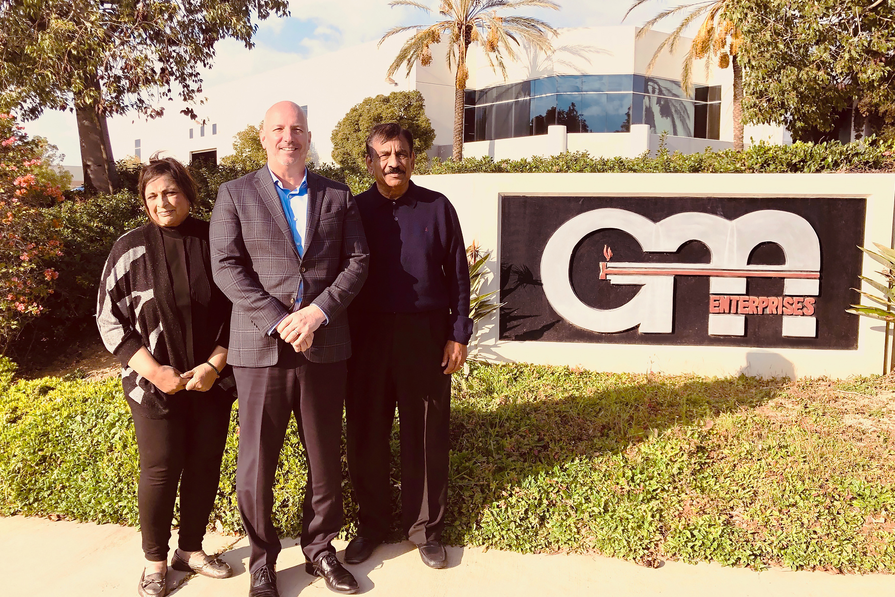
Nitrex, a global provider of fully integrated heat-treating solutions and technologies based in Montreal, Canada, acquired G-M Enterprises, a manufacturer of vacuum furnaces, headquartered in Corona, California.
Mrs. Veena Jhawar, G-M Enterprises COO; Mr. Jean-François Cloutier, Nitrex CEO; Mr. Suresh Jhawar, G-M Enterprises President
The addition of G-M Enterprises will further expand Nitrex’ integrated heat treatment solutions to customers; both share the same goal of providing technologies that focus on customer workflow and efficiency while maximizing the life span and quality of engineered parts and components.
Jean-Francois Cloutier, Nitrex CEO
“This acquisition will allow Nitrex to bolster its turnkey solutions business by bringing a new, innovative and broader mix of heat treatment systems to our customers,” said Jean-Francois Cloutier, Nitrex CEO. “We also look forward to welcoming the entire G-M Enterprises’ team into the Nitrex family.”
“Joining forces with Nitrex and becoming part of its family of companies will ensure we keep pace with our customers’ evolving needs and expectations,” says Suresh Jhawar, G-M Enterprises President. “What this means for the future of G-M Enterprises is an opportunity to enhance our products and services, expand our international presence further by leveraging the resources, expertise, and capital of Nitrex.”
A global technology group, an industrial gases company, an additive and design company, and an engineering university in Germany have entered into a research partnership with the end goal of supporting the aerospace and automotive industries through their research and development of aluminum based-alloys.
Oerlikon, a global technology group, entered into a research partnership with Linde, an industrial gases company, GE Additive, an additive and design company, and the Technical University of Munich (TUM), a leading German university in engineering, to conduct additive manufacturing (AM) research with the aim of developing new high-strength, lightweight aluminum-based alloys that can serve the safety and weight reduction needs of the aerospace and automotive industries.
Dr. Marcus Giglmaier, Project Manager for the AM Institute
This collaboration seeks to address the challenge of aluminum AM. “There are significant challenges during the AM of aluminum alloys because the temperatures reached in the melt pool create an extreme environment that leads to evaporation losses of alloying elements that have comparatively low boiling temperatures — such as magnesium,” said Dr. Marcus Giglmaier, project manager for the Additive Manufacturing Institute and research funding manager. “Additionally, the cooling rates of more than 1 million °C per second, create high stresses during the solidification process, which can cause micro cracks in the solid material.”
The project draws on the strengths of each of its members. Oerlikon’s experience in powder and material science will contribute to the development of the novel material; Linde’s technology and expertise in gas atmosphere control and evaporation suppression during the AM process – including the processing of aluminum-based alloys – overcomes impurities within the print chamber, which will help manufacturers achieve optimal 3D-printing conditions; GE Additive will assist in the collaboration; and, for its part, the Institute of Aerodynamics and Fluid Mechanics (AER) at TUM will be able to provide a detailed understanding of the physical phenomena taking place during the AM process using numerical simulations.
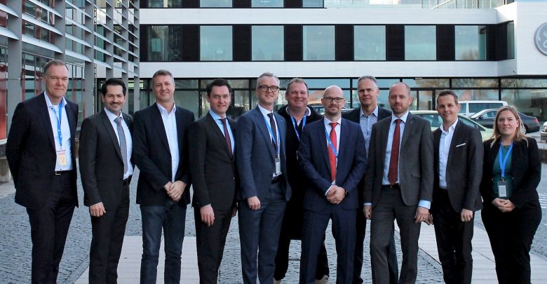
From left to right: Dr Sven Hicken (Business Unit Head, Oerlikon AM), Prof Thomas Hofmann (President, TUM), Jason Oliver (President and CEO, GE Additive), Dr Wolfgang Dierker (CEO, GE Germany), Dr Christoph Laumen (Executive Director R&D, Linde AG), Prof Michael Suess (Chairman of the Board of Directors, Oerlikon Group), Dr Christian Haecker (Head of Industrialisation, Oerlikon AM), Dr Andreas Lessmann (Managing Director, GE Additive Germany GmbH, Senior Leader, Legal Operations), Dr Christian Bruch (Executive Vice President & CEO, Linde Engineering), Andreas Rohregger (Head of Global Properties, GE Additive), Dr Alice Beck (Deputy Director, TUM ForTe) (Courtesy Oerlikon)
A global materials engineering group explored alternative methods of applying a hard surfacing alloy at the ITSC conference in Japan.
Engineers from Wall Colmonoy Corp. discussed in a conference presentation how the properties of a hard surfacing alloy change when applied by different methods. Alloy Ni-15Cr-15W-3B-4Si-3.5Fe-0.6C is a hard surfacing alloy designed to extend the life of OEM parts that are subjected to various wear mechanisms in service. The alloy can also be used to repair/rebuild those worn parts and extend service life.
This hard-surfacing alloy can be applied by various methods, including thermal spray processes, laser cladding, PTA welding, GTAW, OFW, and GMAW. This study compared the properties of the alloy applied by different methods using various test procedures, and also included the cost/benefit ratio of each.
Test procedures included abrasion testing by ASTM G-65; erosion testing by ASTM G-76; Vickers hardness by ASTM E-92; and Rockwell hardness by ASTM E18. In addition, metallographic examples of the test specimens were prepared.
A steel producer based in Fort Wayne, Indiana, recently announced the expansion of their rolling mill, which will include a 3-MW induction furnace to heat the stock coming from the existing mill.
Steel Dynamics USA announced the expansion at their Columbia City, Indiana, location. Among other equipment being added are a 70-m conveyor connecting the existing medium section mill to the new spooler line, six housingless SHS 180 roller stands, complete with quick stand-changing table, a 6-pass Delta-type finishing block driven by a low-voltage- 2.5-MW motor and finishing services.
SDI and Danieli teams studied a temporary removable solution, steel support structure to support the existing furnace-exit roller table, allowing the execution of the Billet Welder concrete foundation with only minor impact to the MSM (Medium Section Mill) production schedule.
A western Pennsylvania heat treat provider recently completed construction of a new brazing and assembly room, built primarily to accommodate a large aluminum brazing project for a specific customer.
Bob Hill, president of Solar Atmospheres of Western PA
Solar Atmospheres of Western PA, based in Hermitage, Pennsylvania, stated that the room will also be used for other brazing and assembly work.
“During successful development and prototype runs, our customer, along with Solar management, understood that in order to bring this critical aluminum brazing project to full production a separate braze/assembly room would be needed,” said Bob Hill, president of Solar Atmospheres of Western PA. “We worked together with our customer to develop the best space that is in close proximity to the vacuum furnace being utilized.”
Main photo credit/caption: Solar Atmospheres / The inspection of critical braze joints being analyzed within Solar’s newly constructed Braze-Assembly room.
This article continues the ongoing discussion on Equipment Selection for Induction Hardening by Dr. Valery Rudnev, FASM, IFHTSE Fellow. Six previous installments in Dr. Rudnev’s series on equipment selection addressed selected aspects of scan hardening and continuous/progressive hardening systems. This post is the third in a discussion on equipment selection for one of four popular induction hardening techniques focusing on single-shot hardening systems.
Previous articles in the series on equipment selection for single-shot hardening are here (part 1) and here (part 2). To see the earlier articles in the Induction Hardening series at Heat TreatToday as well as other news about Dr. Rudnev, click here.
Single-Shot Inductors for Non-Cylinder Parts
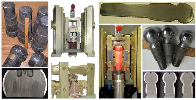
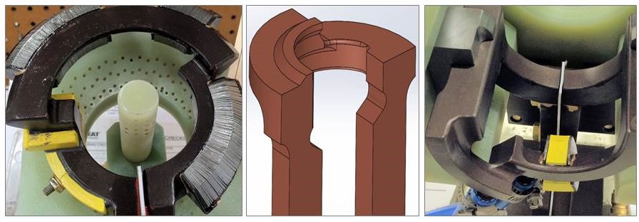
Single-shot inductors can be successfully used for hardening not only components of classical cylinder geometries but other geometries as well. This includes workpieces of general conical shapes, such as elliptic, parabolic, hyperbolic geometries—and the list can grow. As an example, Figure 1 shows induction surface-hardened ball joints (ball studs) and the single-shot inductors used to harden them. Ball studs are used in automotive, off-road, and agricultural machinery and can be different in shape and size (Compare images on the left in Figure 1 with images on the right.), requiring noticeably different hardness patterns.
Figure 1. Surface-hardened ball joints (ball studs) and single-shot inductors used for its hardening. (Courtesy of Inductoheat Inc., an Inductotherm Group company.)
In any attempt to scan harden workpieces with appreciable diameter changes, the scan coil must have a sufficient gap to clear the largest diameter. When scanning the section(s) of the workpiece with smaller diameters, an inductor-to-shaft air gap might be very large, resulting in low electrical efficiency and potentially exhibiting difficulties in load matching as well as in controlling the austenitizing pattern along the length of the part producing "cold" and "hot" spots. Additional difficulties may appear in controlling the hardness pattern in regions (e.g., near geometrical irregularities) where good control is most needed.
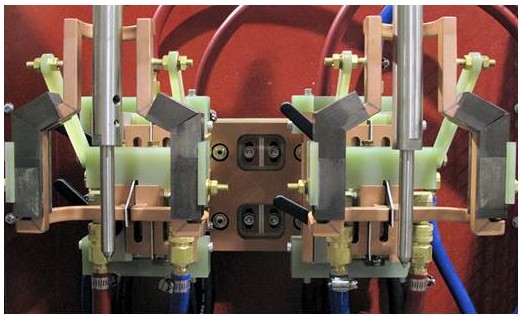
Thus, the substantially different workpiece-to-inductor electromagnetic coupling variations might not permit using classical multiturn solenoid coils or scan inductors. In contrast, single-shot inductors allow not only better electromagnetic coupling along the entire length of heat treated components (Figure 2) but also better address the geometrical irregularities of heat treated workpieces, producing the required hardness patterns at minimum process times with superior metallurgical quality.
Figure 2. Single-shot inductors allow better electromagnetic coupling along the length of heat treated components properly addressing the geometrical complexity of the workpiece. (Courtesy of Inductoheat Inc., an Inductotherm Group company.)
As stated in Part 1 of this series, in contrast to scan hardening, a single-shot inductor can be contoured along the length of the part properly addressing the geometrical complexity of the workpiece. Furthermore, the use of flux concentrators helps drive the current into the desired areas and allows producing a well-defined hardness profile with minimum distortion. The trade-off here is that more finesse is required in the design stage to produce the properly profiled single-shot inductor at the lowest possible cost.¹ Errors are costly since these inductors are each custom made for a given part or application and modifications can be quite costly. Thus, computer modeling is a helpful assistant as an attempt to keep the development cost down and shorten the "learning curve".
Proper hardening of such components as output shafts, flanged shafts, planet carriers, yoke shafts, sun shafts, intermediate shafts, driveshafts, turbine shafts, and some others may require extensive copper profiling, making a single-shot hardening inductor a complex electromagnetic device.
Certain geometrical features such as flanges, diameter changes, bearing shoulders, grooves, undercuts, splines, etc., may distort the magnetic field generated by an inductor, which, in turn, can cause temperature deviations, making it challenging to achieve certain hardness patterns.
For components containing fillets, it is often necessary to increase the heat intensity in the fillet region owing to the geometrical specifics. Also, the larger mass of metal in the proximity of the heated fillet and behind the region to be hardened produces a substantial thermal “cold sink” effect.¹ This draws heat from the fillet due to thermal conduction, which must be compensated for by generating additional heating energy in the fillet area.
Needed energy surplus can be achieved by narrowing the current-carrying face of the crossover segment of the single-shot inductor (Figure 3). Here is a simplified illustration of an impact of a copper profiling of the inductor’s heating face: if the current-carrying portion of the inductor heating face is reduced by 50 percent, there is a corresponding increase in current density. This will be accompanied by an increase of the eddy current density induced within the respective region. According to the Joule effect, doubling the induced eddy current density increases the induced power density roughly by a factor of four. Also, attaching a magnetic flux concentrator to certain areas of the hardening inductor further enhances the localized heat intensity.
Figure 3. Longitudinal leg sections of single-shot indicators and their crossover segments can be profiled by relieving selected regions of the copper to accommodate workpiece geometrical features. Attaching a magnetic flux concentrator to certain areas of the inductor further enhances localized heat intensity. (From V. Rudnev, A. Goodwin, S. Fillip, W. West, J. Schwab, S. St. Pierre, Keys to long-lasting hardening inductors: Experience, materials, and precision, Adv. Mater. Processes, October 2015, pp. 48–52.)
When using a single-shot inductor, it is particularly important that the workpiece is properly located in the heating position because seemingly minor dislocations may noticeably affect the heat treat pattern and metallurgical quality of hardened parts.
Traditionally designed single-shot inductors may exhibit high process sensitivity that is associated with the electromagnetic proximity effect.¹ A change in positioning of the workpiece inside the single-shot inductor attributed to excessive bearing wear of the centers, improper machining of the centers and fixtures, incorrect part loading, and other factors may produce a correspondent appreciable variation in the hardness pattern (particularly within the fillet region, undercut areas, and the part’s end zone). A reduced hardness case depth and the formation of unwanted microstructural products associated with incomplete phase transformation may be the result of that. Magnitude and distribution of transient and residual stresses might also be altered. Thus, attention should be paid to part’s reliable positioning during heating and quenching cycles.
As can be concluded, there are good reasons for using single-shot hardening, scan hardening, or continuous/progressing hardening approaches in induction hardening applications. The decision must be well thought out based on many factors such as geometry specifics, product quality, production rate, design proficiency, limitations of available equipment, reliability requirements, cost considerations, and some other factors.
The next installment of this series, “Dr. Valery Rudnev on . . . ”, will continue the discussion on design features of induction single-shot hardening systems.
Extensive wear or fatigue from friction and contact stress cause many engineering components made of ferrous or titanium alloys to fail. In this Best of the Web
Edward Rolinski,”Dr Glow”, Advanced Heat Treat
Technical Tuesday feature, Edward Rolinski, aka Dr. Glow, from Advanced Heat Treat Corp., compares “wear resistance between engineering components that were carburized vs nitrided,” originally published in his article, “Tribological Performance-Enhancing Surface Treatments for Improving Durability of Engineering Components” at AHT’s website.
An excerpt:
“The results of the tribological studies strongly suggest that for many engineering components, the application of nitriding may be more beneficial than carburizing since the nitrided layer had better wear properties than the carburized layer despite the fact that the layer was about four times as thick.”
Rolinski defines the uses, advantages, and tribological behavior of nitrided and carburized steel and provides illustrations of samples subjected to both treatments.
Main image photo credit/caption: Advanced Heat Treat Corp / Advanced Heat Treat’s Cullman, Alabama, location ion nitroding vessel, which the company says is one of the largest in the United States—”big enough for two small cars to fit inside.”
A cooperative research and development agreement (CRADA) has recently been reached that has as its objective improving the process reliability of electric beam melting technology (EBM) through the use of in-situ process monitoring and closed loop control, expanding the technology to new materials systems, specifically nickel-based superalloys, and validating microstructure and properties of titanium Ti-6Al-4V materials fabricated with increased deposition rate.
GE Additive announced that it entered into the five-year CRADA with the US Department of Energy’s Oak Ridge National Laboratory (ORNL). The agreement focuses on processes, materials, and software to drive industrialization and encourage the broader adoption of additive manufacturing technology.
The new CRADA, which covers all GE Additive equipment, materials and engineering services capabilities, focuses on developing and implementing novel additive technologies into commercial products including:
Building on existing research into process simulation methodologies and in-situ monitoring and quality control, on both EBM and direct metal laser melting (DMLM) systems
Materials modeling and development
Industrialization and commercialization of equipment and processes
Moe Khaleel, associate laboratory director for Energy and Environmental Sciences at ORNL
“Our pioneering research with GE Additive was essential to resolving scientific challenges in advanced metals manufacturing using new electron beam methods,” said Moe Khaleel, associate laboratory director for Energy and Environmental Sciences at ORNL. “We’re excited to again push the boundaries with GE and lower the barriers for widespread adoption of more efficient, low-cost manufacturing techniques.”
Daniel R. Simmons, assistant secretary for DOE’s Office of Energy Efficiency and Renewable Energy
“By collaborating with industry partners such as GE Additive, DOE’s Oak Ridge National Laboratory brings its multi-disciplinary expertise and capabilities to bear on real-world challenges and moves technologies into the marketplace where they will have the greatest economic impact,” said Daniel R. Simmons, assistant secretary for DOE’s Office of Energy Efficiency and Renewable Energy.
Josh Mook, innovation leader, GE Additive
“We’re really looking forward to applying the collective brainpower and expertise from both organizations to addressing the challenges around industrialization, but we also have an eye on the future,” said Josh Mook, innovation leader, GE Additive. “The next wave of additive technology is already upon us—whether that’s binder jet or rapid advances in software—so we’re excited to see where the next five years will take us.”
The agreement supersedes an existing CRADA in place since 2012 between ORNL and GE Additive Arcam EBM.
Main photo credit / caption: GE Additive / From left to right: Christine Furstoss, chief technology officer, GE Additive; Daniel Simmons, assistant secretary, US Department of Energy – Office of Energy Efficiency and Renewable Energy; Moe Khaleel, associate laboratory director for Energy and Environmental Sciences and Chris Schuppe, general manager, engineering, GE Additive.
During the day-to-day operation of heat treat departments, many habits are formed and procedures followed that sometimes are done simply because that’s the way they’ve always been done. One of the great benefits of having a community of heat treaters is to challenge those habits and look at new ways of doing things. Heat TreatToday’sannual 101 Heat TreatTips, tips and tricks that come from some of the industry’s foremost experts, were featured in the 2019 Heat Treat Show Edition, as a way to make the benefits of that community available to as many people as possible. This edition is available in a digital format here.
Today we offer the first Heat TreatTip from the 2019 edition: Debbie Aliya of Aliya Analytical Inc. on “Where You Measure Matters”, categorized under Materials Testing. Debbie is also one of Heat TreatToday’s featured Heat TreatConsultants. Click here for more information on our Consultants’ page.
Heat TreatTip #6
Where You Measure Matters
Eugene Gifford Grace (August 27, 1876 – July 7, 1960) was the president of Bethlehem Steel Corporation from 1916 to 1945. He also served as president of the American Iron and Steel Institute and sat on the board of trustees for Lehigh University, of which he was an alumnus. One of his famous quotes is as follows:
“Thousands of engineers can design bridges, calculate strains and stresses, and draw up specifications for machines, but the great engineer is the man who can tell whether the bridge or the machine should be built at all, where it should be built, and when.”
If you check out the additional accomplishments of Mr. Grace, you will see that he was a successful and smart person. Maybe all of us are not capable of reaching such breadth of vision as he articulated above, but as heat treaters, do we simply accept the specification given? Or do we stop to ask if the specification has been properly determined?
With modern computer added stress analysis (FEA), we have at our fingertips a way to move beyond both the “guess and test” and the “copy the historical spec” methods of determining the case depth. Within “guess and test,” of course there are scientific guesses and scientific wild guesses. If you are using a wild guess, chances are that the field is the test lab!
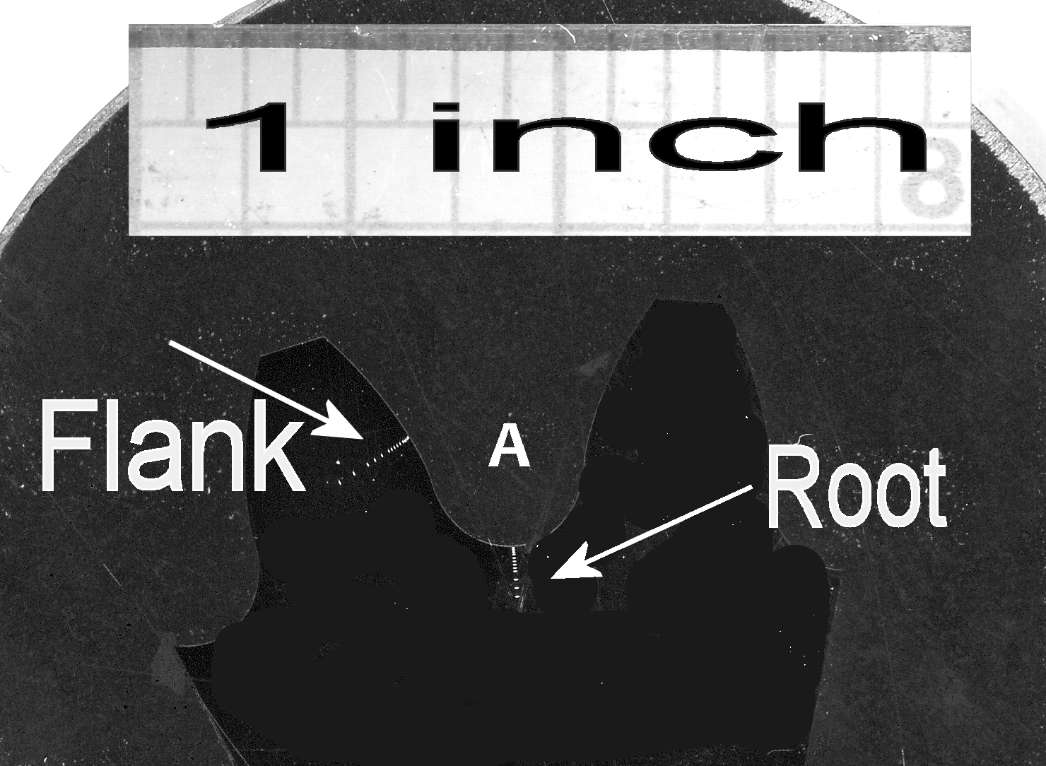
Figure 1. Metallurgical mount holding a cross-section of the steel gear.
Especially for carburized components, deeper case is more time in the furnace, and thus more expensive. I continue to wonder why, if even back in the 1950s, thousands of engineers were available who could calculate stresses and strains and thus set a quantitative foundation for a case depth, in 2019, so few people take advantage of modern technology to optimize the cost of their products.
If you are not ready to take this big step toward design optimization, maybe you would consider always using effective case depth, based on hardness and thus linked to tensile strength, instead of total case depth, which is not linked to any durability or strength criteria.
Figure 1 shows the metallographic cross-section that was used to measure the hardness. Each white pin point is a Knoop 500 gram hardness indentation. The cross-section of the gear was mounted in black epoxy resin. Figures 2 to 4 show the data collected to determine the effective case depths to the common Rockwell C 50 criteria.
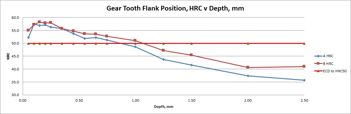
Figure 2. Knoop 500 gram hardness data converted to Rockwell C at the tooth flank.
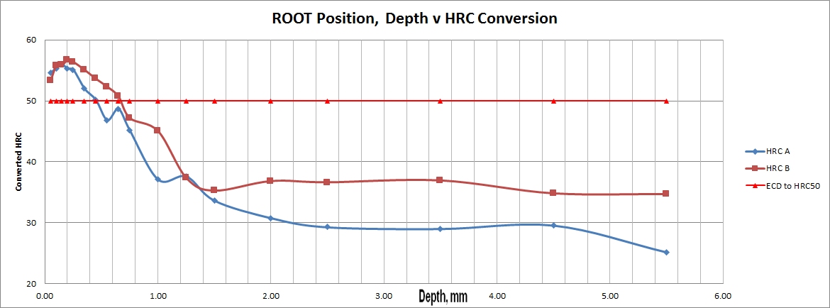
Figure 3. Same data but for Root position.
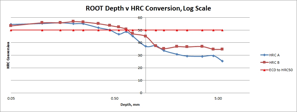
Figure 4. Same data as shown in Figure 3, near surface information easier to see.
The effective case depth is the depth where the hardness dips below HRC50. For Gear Tooth Flank A, that value was 0.85 mm. For another gear from the same lot, it was over 1.08 mm. But for the root areas, between the teeth—the high-stress area, the effective case depths were only 0.45 and 0.65 mm, respectively. Figure 3 shows the same data as Figure 2, but using a logarithmic scale, illustrating what’s going on near the surface layers more clearly.
In any case, there’s a big difference between the two test locations, and this shows the importance of making sure that all relevant features of the component are adequately characterized!
If you have a heat treat-related tip that would benefit your industry colleagues, you can submit your tip(s) to doug@heattreattoday.com or editor@heattreattoday.com.
A Texas-based aluminum company recently launched operations of its previously idled aluminum rolling mill with a ribbon-cutting ceremony.
Texarkana Aluminum produces common alloy for the North American service center industry is a fully integrated aluminum rolling mill with casting, hot mill, cold mill, and finishing capabilities. Ta Chen International Inc, which owns Texarkana, invested $460 million to restart the previously idle rolling operation. Included in the plans are software and hardware upgrades for the rolling mill and a goal of 300 million lbs of aluminum coil production per year once the plant reaches full operation.
The event at the plan in Nash, Texas, was attended by company executives as well as local, regional and state economic and political organizations.
“This plant will be fully operational come May 2020,” said Calum Donnachie, chief operating officer of Texarkana Aluminum Inc.
Main photo credit / caption: Hunt Mercier of Texarkana Gazette / Arkansas Gov. Asa Hutchinson speaks to Harvey Wrubel at the Texarkana Aluminum ribbon-cutting ceremony in Nash, Texas.