Earlier this year, four 100-pound drums filled with palladium—which is comparable in value to gold—were stolen from a chemical plant in Georgetown, South Carolina, by thieves who accessed the facility by cruising up the Sampit River, which is known to be home to alligators.
3V Sigma USA, which manufactures specialty chemicals from synthetic polymers to organic chemistry molecules, was housing the palladium, which is mined domestically in Montana but primarily sourced from Russia and South Africa. The masked bandits, who were seen on surveillance videos, knew how to navigate the river, quickly loaded their vessel, and absconded with the precious metal.
According to an article in The Post and Courier, the value of palladium has risen in recent years and with it an increase in the theft of catalytic converters, which contain the metal for this purpose.
“Its value has invited the interest of thieves, as reports of stolen catalytic converters regularly make headlines in news outlets across the globe.
This month, a Philadelphia television station reported that one person’s van was stripped of the palladium-laden device by a group of thieves. It was the second time the person’s car was vandalized for the converter, according to the report.
Also this month, in Oxford, England, thieves targeted vehicles at park-and-rides. And in Berkeley, Calif., converters from dozens of vehicles were stolen in recent weeks.”
3V didn’t report the theft until 5 days after the heist, and the crime remains unsolved.
Main Image Credit/Caption: Brad Nettles (The Post & Courier) / 3V chemical plant located in Georgetown, South Carolina, the site of palladium heist.
A Pennsylvania vacuum furnace manufacturing company has recently relocated its operations to provide more space for building furnaces and furnace equipment.
Solar Manufacturing Inc. has moved from Souderton to Sellersville, Pennsylvania, where the new facility is located on a combined 8.5 acres just three miles from the previous location. The newly-constructed building houses 40,000 square feet of manufacturing space and 17,500 square feet designated office space, with an option for an extra 22,500 square foot addition to the manufacturing building in the future. The move was achieved in several phases, taking place over several weeks in September and October. Despite the scope of the project, Solar Manufacturing experienced only a few minor interruptions.
William Jones, owner of Solar Manufacturing, Inc.
“Solar Manufacturing has expanded throughout the many years since our inception, resulting in our employees working from several different buildings,” said Jim Nagy, President of Solar Manufacturing. “With this move, we are finally united under one roof. Not only is the new space very handsome, but it is also a well-thought-out facility. It is equipped with and geared up for efficient production, with enough capacity to serve our customers well into the future, especially those who need very large vacuum furnaces.”
“This new facility provides us the space we need to grow and consolidate all our staff in one facility,” said William Jones, who along with his wife, Myrtle Jones, owns Solar Manufacturing, Inc. “Now that we’re officially settled, we’re eager to use the new building to its fullest potential.”
Heat TreatToday recently released the latest round of 101 Heat TreatTips in the fall 2019 issue of Heat TreatToday (click here for the digital edition). One of the great benefits of gathering with a community of heat treaters is the opportunity to challenge old habits and look at new ways of doing things. The Heat TreatTips is another opportunity to learn the tips, tricks, and hacks shared by some of the industry’s foremost experts.
Ryan Neiss of Taylor Winfield Technologies
Today’s Technical Tuesday features a tip on Induction Heating that missed inclusion in the magazine, but it’s significant enough to get its own headline. From Ryan Neiss of Taylor Winfield Technologies, we bring you “Seasonal Cooling Water Adjustments for Induction Power Supplies”.
If you have a heat treat-related tip that would benefit your industry colleagues, you can submit your tip(s) to doug@heattreattoday.com or editor@heattreattoday.com.
Heat TreatTip: Induction Heat Treating
Seasonal Cooling Water Adjustments for Induction Power Supplies
A proper preventative maintenance plan is critical to the performance of induction heating power supplies. One of the main culprits of downtime is reduced water flow and water quality. While water quality is a very important topic that must be maintained within the OEM specifications, this tip is going to address the importance of seasonal water adjustments.
Water flows through the inside of the power supply cooling critical devices, like power semiconductors, capacitors, transformers, buss, etc. If the temperature is not adjusted for seasonal climate changes, many users may experience water condensation inside the power supply cabinet. This is not a good situation, because the uncontained water can drip into places where water should not be and potentially cause severe damage to the power supply. Depending on how much water damage there is will determine the amount of production loss and costs of this easily preventable mistake.
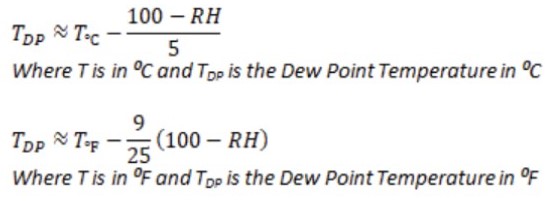
The temperature setpoints for your cooled water source must always be above the temperature dew point in order to prevent condensation. Most weather apps have current dew points, relative humidity, and temperature. Additional climatic resources for predictive planning include noaa.gov and ashrae.org.
Here’s a simple approximation of the dew point temperature from temperature and relative humidity (only apply if relative humidity is above 50%).
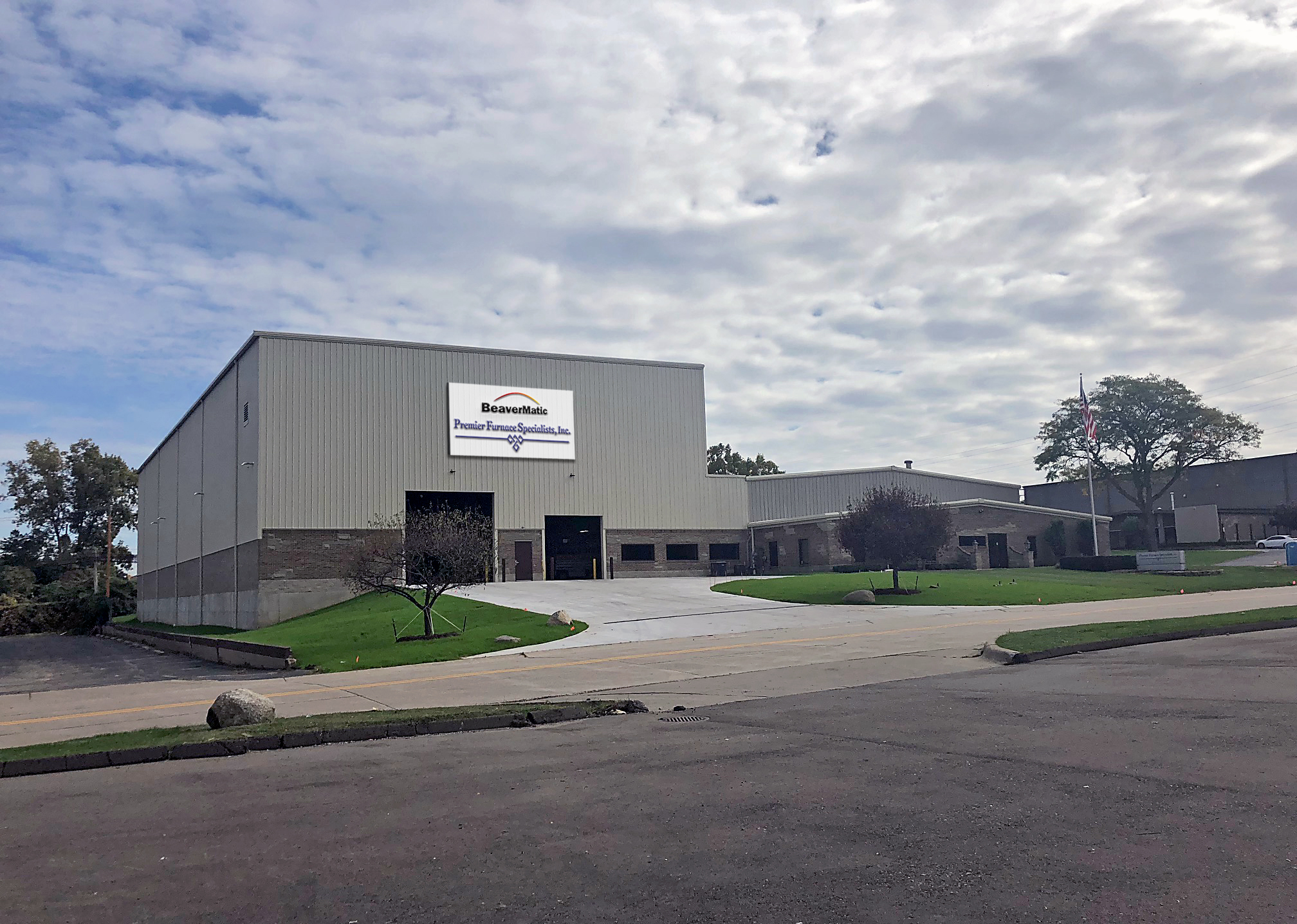
Premier Furnaces new 40,000 sq. ft. facility in Farmington Hills, MI.
A Michigan-based heat treat equipment manufacturer recently announced a major building expansion that will provide more space for building larger furnaces.
Premier Furnace Specialists and BeaverMatic have completed the expansion at one of their Farmington Hills facilities, which includes a new plant for administration and manufacturing, as well as a new plant for engineering and manufacturing. This expansion provides 45’ high ceilings with two large (25 ton and 10 ton) overhead cranes to complement the existing two (10 ton) overhead cranes. The total square feet under one roof is now 40,000. The $2.5 million expansion was needed for the continued growth of both companies, the magnitude of the atmosphere furnaces being built, and to employ additional employees.
Sven-Olaf Sauke, head of R&D at ZPF GmbH, is responsible for research and development at ZPF GmbH and works on innovative solutions for flame-resistant materials, intelligent sensor technology and control systems in melting furnaces. (Source: ZPF GmbH)
The future is moving inexorably towards smart factories, but many smelting plants are still stuck with assembly line production in Industry 2.0 without IT support. Central elements of a modern factory of the 21st century—such as the interface to a central database server or intelligent, heat-resistant automation including sensor technology enabling all facilities to communicate with each other—are frequently not available. Although there are numerous protocols in existence for this purpose, the possibility of retrofitting these protocols standards does not exist in many older facilities. A lack of expenditure resources and the absence of vision for the future have often led to missed opportunities.
Therefore, research strategies that build on each other are always recommended in order to keep up with the times. Only in this way can a smelting plant face the numerous challenges of the future in the long term. In this article, Sven-Olaf Sauke, head of R&D at ZPF GmbH, lays out the steps taken by ZPF to invest in the future in order to meet the current requirements of the industry and create a basis for innovative products, serving as a case study for U.S.-based Heat Treat Today readers standing on the cusp of Industry 4.0 readiness with uncertainty about how climate policies will affect U.S. manufacturing.
Melting Furnace 4.0: Thinking Ahead, Developing Further, Moving On
A current challenge in Industry 4.0 is the automation of so-called predictive maintenance. In this process, the system is monitored on an ongoing basis and throughout the entire process (continuous system monitoring) to perform condition-based maintenance work. In a smart factory with a melting furnace, for example, cleaning could be carried out by a robot that knows all the parameters of a furnace and can take action in good time before a critical degree of contamination is reached. Consequently, the robot automatically prevents a later complete breakdown of the system and a standstill of the entire shop in just a few minutes.
However, as long as there is no suitable and, at the same time, safe sensor technology that can withstand extremely high temperatures, these essential parameters cannot be recorded, even though they are the basis for Industry 4.0. In order to master these complex automation tasks, the entire factory needs extensive knowledge of all important plant data—from the filling level of the furnace to the degree of contamination in the bath area. For this reason, ZPF GmbH, for example, has already laid the foundations for solutions for intelligently networked melting furnaces through various research projects in the past.
Enoptal—from refractory materials to burner technology
At this point, the ZPF project "Enoptal" serves as an example for the beginning of such a research chain. In Germany, as a result of climate policy (surrounding Directive 2009/29/EC), aluminum producers and processors with a total rated thermal input of 20 MW had to limit their CO2 emissions from 2013 and purchase new certificates if necessary. This puts pressure on companies in the aluminum industry to find timely solutions for lower CO2 emissions. Following this, more investment was made in the development of efficient burner technology to reduce energy costs and reduce the impact of greenhouse gases on the environment. The charging methods and cleaning intervals of the furnaces as well as the melting losses were examined and the influence these parameters have on the critical emission values were reviewed.
In order to determine the energy-saving potential in aluminum melting processes, researchers have developed a system for monitoring and controlling the melting process in a joint project between industry and science.
The research project "Enoptal" was funded by the German Federal Ministry for Economic Affairs and Energy, supervised by the Project Administrator Jülich, conducted together with the Technical University Bergakademie Freiberg and successfully completed in 2011. With the help of various field tests, the essential parameters of a melting and holding furnace with a melting capacity of 300 kg/h and a holding capacity of 700 kg were determined, and optimization potential was identified for the refractory material and the burner arrangement resulting in energy savings of up to 10 percent. These fundamental results formed the basis for the next major research project.
Edusal-I + II—from burner technology to sensor technology
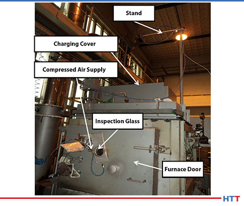
The camera system selected at the IFUM in Hannover for measuring height changes inside the aluminum furnace was tested in the scope of trials at the Technical University in Freiberg. As a first step, the optimal camera position above the charging cover of the furnace was determined, and the camera was then firmly positioned there. (Source: ZPF GmbH + IFUM)
As the next step in this research chain, the melting plant together with other plant components was at the center of the task in order to optimize the entire furnace system. The aim was to search for further energy saving potentials in melting processes with aluminum to minimize melting loss, to improve process monitoring, and to create the basis for a modern and efficient heat recovery system.
Since the field of "measurement technology" in particular has large gaps, the possibilities for a system for monitoring and control were examined in cooperation with the Federal Ministry for Economic Affairs and Energy, the Technical University Bergakademie Freiberg, and the Leibniz University of Hanover. The focus in the projects "Edusal-I and II" was mainly on the development of a measuring technique for the sensory detection of the furnace chamber.
In some areas, water-cooled, optical systems are used for furnace interior monitoring—for example, after the repair of glass troughs.
Although these provide an insight into the condition of the refractory lining and other process parameters, for safety reasons they cannot be used in rough everyday operation or must not be used by operators of aluminum melting plants. If such a system is damaged and the water is unintentionally heated from 68°F (20°C) to 1652°F (900°C), the sudden change in volume of the water can lead to explosions and thus to serious damage to property and persons. For the first time, the measurement method developed with the associated software made it possible to precisely determine the amount and position of material on the melting bridge during melting operation. In this context, a dynamic burner system was developed that can be regularly aligned to the melting charge via the recorded measurement data and thus increases the efficiency of the overall system.
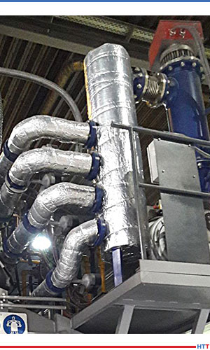
In addition, the plant was equipped with a heat exchanger system. With the help of the exhaust gas, the required burner air is heated in the heat exchanger and directed to the burners. This heating results in a higher temperature level during the combustion process and leads to significant gas savings. The research project ended successfully in 2016 and enabled a further increase in energy efficiency of up to 15 percent in the melting plant. On this basis, assemblies were revised for series use. Today there are plants ready for trial operation which have been successfully tested. The measured values from the research project are confirmed at these plants in the rough melting operation.
AlSO 4.0—from sensor technology to automation
(Above figures: In further cooperation with the Federal Ministry for Economic Affairs and Energy and the Bergakademie Freiberg, the possibilities for a system for monitoring and control were examined. The main focus was placed on the development of a measuring technique for the sensor detection of the furnace chamber. In this context, ZPF has developed a dynamic burner system that can be continuously aligned to the melting charge via the recorded measurement data and thus increases the efficiency of the overall system. (Source: ZPF GmbH)
Thanks to the findings from the Edusal II project on sensor technology, a non-contact optical test method was developed which detects a change in the state of the aluminum block.
This is a camera system with a special evaluation logic that is able to detect non-molten aluminum on the bridge during the melting process. This new sensor technology enables an objective evaluation of the melting process in the aluminum furnace, and the user can automatically determine the current quantities of the material to be molten. In this way, characteristic values can be derived for objective evaluation of the melting performance guaranteeing continuous monitoring throughout the entire melting process. It also opens up further possibilities for automatic control processes within a smart factory.
All results of these research projects serve as a basis for the current project called AlSO 4.0 (aluminum melting furnace 4.0).
Research on control and evaluation options for automation, required for further steps in the process chain, is conducted in close cooperation with the Technical University Bergakademie Freiberg, the University of Bremen, and the Leibniz University of Hanover as well as aluminum melting furnace operator and is funded by the Federal Ministry for Economic Affairs and Energy. In this process, the areas to be examined are extended to the entire furnace system and the first prerequisites are created for integrating adjacent peripherals and achieving the desired increase in efficiency. The frequently described scarcity of resources will be the driver for further technical development, which cannot be achieved without research work. Long-term and systematic research pays off.
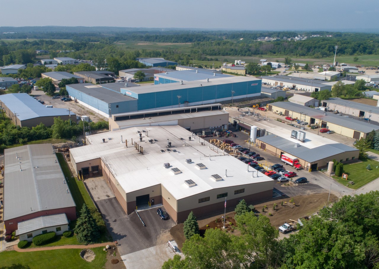
New building opens for ThermTech of Waukesha, Wisconsin.
A heat treating services provider based in Waukesha, Wisconsin, recently completed an 11,000 square foot addition, increasing its capacity to serve tooling, defense, oil & gas, mining, construction, medical, and general metal manufacturing companies in the Midwest.
ThermTech of Waukesha is celebrating Manufacturing Month with the grand opening of the new facility and will welcome customers and associates to an Open House on October 25th from 10 am to 3 pm.
Mary Wiberg Springer, vice president of ThermTech
“At ThermTech, people make the difference,” said Mary Wiberg Springer, vice president of ThermTech. “From our customer service reps to process metallurgists and expert heat treaters, you have a skilled and experienced team serving you. We invite customers and associates to come and tour our new, expanded facilities and renovated shop floor to understand our capabilities and the advantages we bring to the table. For over three decades, we have stood firm in our commitment to meeting customer needs through continuous innovation, modernization, and advancements in heat treating skills. Bringing on the latest technology and equipment in a bigger, better facility allows us to serve more customers across the country, in a wide variety of industries. We couldn’t think of a better way to celebrate Manufacturing Month than by opening the doors to this new facility.”
ThermTech recently added an IQ furnace to its equipment capabilities, performing carburizing or hardening with operating dimensions of 54″ wide x 72″ long x 36″ high or parts up to 10,000 pounds.
Heat Treat 2019 is coming, and one of the great benefits of gathering with a community of heat treaters is the opportunity to challenge old habits and look at new ways of doing things. Heat Treat Today’s101 Heat TreatTips is another opportunity to learn the tips, tricks, and hacks shared by some of the industry’s foremost experts.
Today’s Technical Tuesday features 10 Tips from a variety of categories, including SCR Power Controls (56), Cooling Systems (64), Combustion (66, 101), Induction Heat Treating (71), Thermocouples (79), AMS2750 (86), Vacuum Furnaces (92), and Miscellaneous (41, 87). These tips come from the 2018 list of 101 Heat TreatTips published in the FNA 2018 Special Print Edition. This special edition is available in a digital format here.
If you have a heat treat-related tip that would benefit your industry colleagues, you can submit your tip(s) to doug@heattreattoday.com or editor@heattreattoday.com—or stop by to see us at Booth #2123 in Detroit!
Heat TreatTip #41
Discolored Part—Who’s to Blame?
If your parts are coming out of the quench oil with discoloration and you are unsure if it is from the prewash, furnace, or oil quench, you can rule out the quench if the discoloration cannot be rubbed off. Check this before the part is post-washed and tempered.
Other possible causes:
Can be burnt oils as parts go through the quench door flame screen
Poor prewash
Furnace atmosphere inlet (particularly if it is drip methanol)
When we buy a pint of beer we don’t expect the head (or foam) to be ½ the glass. We can get this situation when we pay for our plant’s electricity; we pay for both the working power that drives the process (analogy: beer) and reactive power that doesn’t directly drive the process (analogy: foam/head). The lower the Power Factor the worse this situation. The latest SCR devices can help combat this while maintaining precise control and reducing overall peak load demands (using flexible firing methods).
Plan for future growth. It is more cost-effective to provide additional capacity while equipment is being installed. Simple planning for the addition of future pumps (e.g. providing extra valved ports on tanks) and space for heat transfer equipment (e.g. pouring a larger pad or adding extra piers) can save considerable money down the road with little upfront expenditure. Consider installing one size larger piping for the main distribution supply and return. If this is not possible make sure you can add an additional piping run on the hangers you will install now.
Above all, be sure to include all necessary drains, vents, isolation valves, and plenty of instrumentation. These items are critical aids in maintenance and troubleshooting and future system expansion.
Don’t neglect burner tuning—a 1% reduction in excess O2 in the flue products can save you $1,000.00/year on your IQ batch or $2,000.00/year on a 2000-pound/hour continuous furnace—not to mention consistent temp uniformity, better heat-up rates. Pretty good payback for a couple of hours’ work.
Tube & Pipe Heat Treatment Is Different Than Solid Cylinder Heat Treating
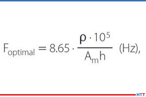
Induction heating of tubes and pipes is somewhat different from the heating of solid cylinders. There is a difference in the frequency selection that would maximize energy efficiency for heating tubular products as compared to solid cylinders. In tube and pipe heating, the frequency, which corresponds to maximum coil efficiency, is typically shifted toward lower frequencies providing larger current penetration depth than the tube wall thickness (except for heating of tubes with electromagnetically small diameters). This condition can produce an improvement in electrical efficiency of 10–16 % and even higher. One simplified formula that is used in industry for rough estimate of the electrically efficient frequency is shown in the image, where:
ρ – electrical resistivity of heated metal (Ω*m)
Am = average diameter; Am = (Tube O.D. – h) (m)
h = wall thickness (m)
In cases when induction heaters cannot be considered to be electromagnetically long coils, the values of the optimum frequency will be higher than the values suggested according to formula, and computer modeling can help determining its exact value.
Place a yearly blanket order for your SAT probes and ask that they are made from the same coil. This will give you the same correction factors and temperature tolerances.
This standard is gold and unfortunately has a bad rap today because companies feel it’s just added cost into the process. Today’s technology means you can afford AMS2750E compliant controllers and digital recorders for only a few hundred dollars above a standard offer. This investment will be paid back many times over due to the longer lifetime expected with a quality instrument as well as the quality benefits from better drift performance between calibration intervals, redundant recording (in case of record loss), and overall accurate temperature control, leading to less rejects and reduced rework.
When trying to determine a materials response to heat treatment, it is important to understand its form (e.g., bar, plate, wire, forging, etc.), prior treatments (e.g. mill anneal, mill normalize), chemical composition, grain size, hardenability, and perhaps even the mechanical properties of the heat of steel from which production parts will be manufactured. The material certification sheet supplies this basic information, and it is important to know what these documents are and how to interpret them.
Certain alloying elements have a strong influence on both the response to heat treatment and the ability of the product to perform its intended function. For example, boron in a composition range of 0.0005% to 0.003% is a common addition to fastener steels. It is extremely effective as a hardening agent and impacts hardenability. It does not adversely affect the formability or machinability. Boron permits the use of lower carbon content steels with improved formability and machinability.
During the steelmaking process, failure to tie up the free nitrogen results in the formation of boron nitrides that will prevent the boron from being available for hardening. Titanium and/or aluminum are added for this purpose. It is important, therefore, that the mill carefully controls the titanium/nitrogen ratio. Both titanium and aluminum tend to reduce machinability of the steel, however, the formability typically improves. Boron content in excess of 0.003% has a detrimental effect on impact strength due to grain boundary precipitation.
Since the material certification sheets are based on the entire heat of steel, it is always useful to have an outside laboratory do a full material chemistry (including trace elements) on your incoming raw material. For example, certain trace elements (e.g. titanium, niobium, and aluminum) may retard carburization. In addition, mount and look at the microstructure of the incoming raw material as an indicator of potential heat treat problems.
When loading parts, carefully place the workload on the center of the hearth (front-to-back and side-to-side). Make sure it is stable and no part of the load is close to or touching the heating elements. This can create arcing and damage your parts. Tip: Once the load is in place, mark the hearth posts with a hacksaw to quickly find the front and back measurements each time.
Perfect combustion is based upon the concept of neither excess oxygen or a deficiency of oxygen in the combustion process. This is known as stoichiometric or theoretical combustion. Why is this considered as theoretical and not possible under normal field conditions? Consider the factors that can affect your combustion process: temperature of air or gas, pressure fluctuations, gas composition or supply changes, operating conditions, etc. Therefore theoretical combustion is just that: perfect combustion is only possible in a lab setting. Burner adjustment and calibration normally maintains a minimum of 10% excess air to compensate for these variables and avoid operating gas-rich with high levels of CO in the combustion process.
Gary Burdardt, market development manager with Frigel North America
There’s only one constant about technology. It’s always evolving—revealing new innovations and opportunities. And as these new technologies come to light, heat treating operations have new opportunities to reduce cost, increase efficiency, and ensure consistent, optimized part quality, regardless of the job parameters. With the introduction of new process cooling technologies to the heat-treating market, previously unexplored systems become viable solutions for unanswered operating challenges.
When a tempered alloy manufacturer faced strict job requirements that demanded capabilities outside the competences of traditional technologies, a modular process cooling systems designer and manufacturer based in Italy with a North American operation located in East Dundee, Illinois, proposed a process cooling system that addressed key problem areas, while ensuring top system performance. As a result, the company was able to document operational cost savings of over $80,000 per year.
Gary Burdardt, market development manager with Frigel North America, is the author of this case study.
The Need for a Better Cooling Solution
Located on the East Coast, the manufacturer needed to find an alternative process cooling solution for its vacuum furnace cooling operation. It had been using air-cooled chillers, but the costs of continuous operation were too high. Operating as a batch furnace, the heat load of this particular application was specified to be approximately 200 tons, and process cooling water temperature, which was specified at 70°F, presented a significant challenge.
At 70°F, the required temperature was much lower than typical process cooling temperatures. For many vacuum furnace cooling processes, water temperatures can be specified as warm as 100°F for successful heat extraction. Because furnace vessels and resulting materials can reach temperatures as high as 1,300 to 1,700°F, water temperatures of at or near 100°F are able to maintain furnace vessel inner wall temperatures below a maximum (safe) temperature of 300°F. Though the final part temperature can be inconsequential, the batch of product needs to be cooled enough for comfortable handling in downstream operations.
Traditional technologies are capable of maintaining 100°F cooling water year-round. Maintaining temperatures consistently at 70°F is much more difficult. Facing high costs and strict temperature requirements, the manufacturer needed a new process cooling approach.
In this application, the manufacturer identified several process cooling areas of concern that, left unsolved, could jeopardize operations.
First and foremost, process cooling systems needed to adequately reduce heat transmission from the furnace vessel to the ambient environment. In addition, the air-to-water heat exchanger, used for batch cooling inside the chamber, needed to be cooled after the tempering process was complete. Likewise, the diffusion pump, used to evacuate air from the vacuum chamber, as well as the electrical cabinet relied on process cooling for optimized function. If the diffusion pump failed to perform as expected, part quality would be jeopardized, leading to potential contamination and material inconsistencies, and reducing the value of the final product.
Traditional Technology Limitations Explored
Initial investigations into solutions revealed apparent limitations. Traditional process cooling methods were unable to cost-effectively maintain water-cooling temperatures of 70°F. This made finding an alternative solution critical. Three traditional methods were explored:
Evaporative cooling towers
This technology is incapable of achieving consistent temperatures in the 70°F range. Cooling water temperatures are controlled by the wet-bulb temperature, relying on evaporation in ambient air conditions. As a result, they can often only provide 85°F or higher water temperatures to processes year-round. This cooling technology tends to be maintenance-intensive given the reliance on chemical treatment and filtration to maintain water quality. Additionally, evaporative towers consume excessive amounts of water.
Dry fluid coolers
This technology would only be effective in this application when air temperatures were at 55°F or below. Though reducing the need for chemical treatments and eliminating excessive water consumption, this system can only produce water that is typically 10-15 degrees warmer than the dry-bulb temperature, or the ambient air temperature without moisture. As a result, temperature tolerance would be lost during the warmer months. During the colder months, the use of glycol antifreeze solutions is necessary to maintain system functionality, which in many cases requires the use of additional pumping systems and water-to-glycol heat exchangers.
Central chillers
The conventional approach relies on a chilled water system that incorporates chillers to generate 70°F temperatures. This system can be supplemented with a dry fluid cooler if conditions for free cooling were significant enough for payback in three years or less. In many cases, the cold, consistent temperature of the water produced by the chillers is cooler than is necessary for most heat-treating components, leading to increased energy inefficiencies and accrued higher costs.
Faced with the limitations of traditional technologies, the manufacturer turned to an alternative process cooling system for the answer.
Considering an Alternative System
Once traditional methods were thoroughly analyzed, the choice was easy. Providing an alternative solution, the Frigel system design was selected and implemented into the vacuum furnace cooling application.
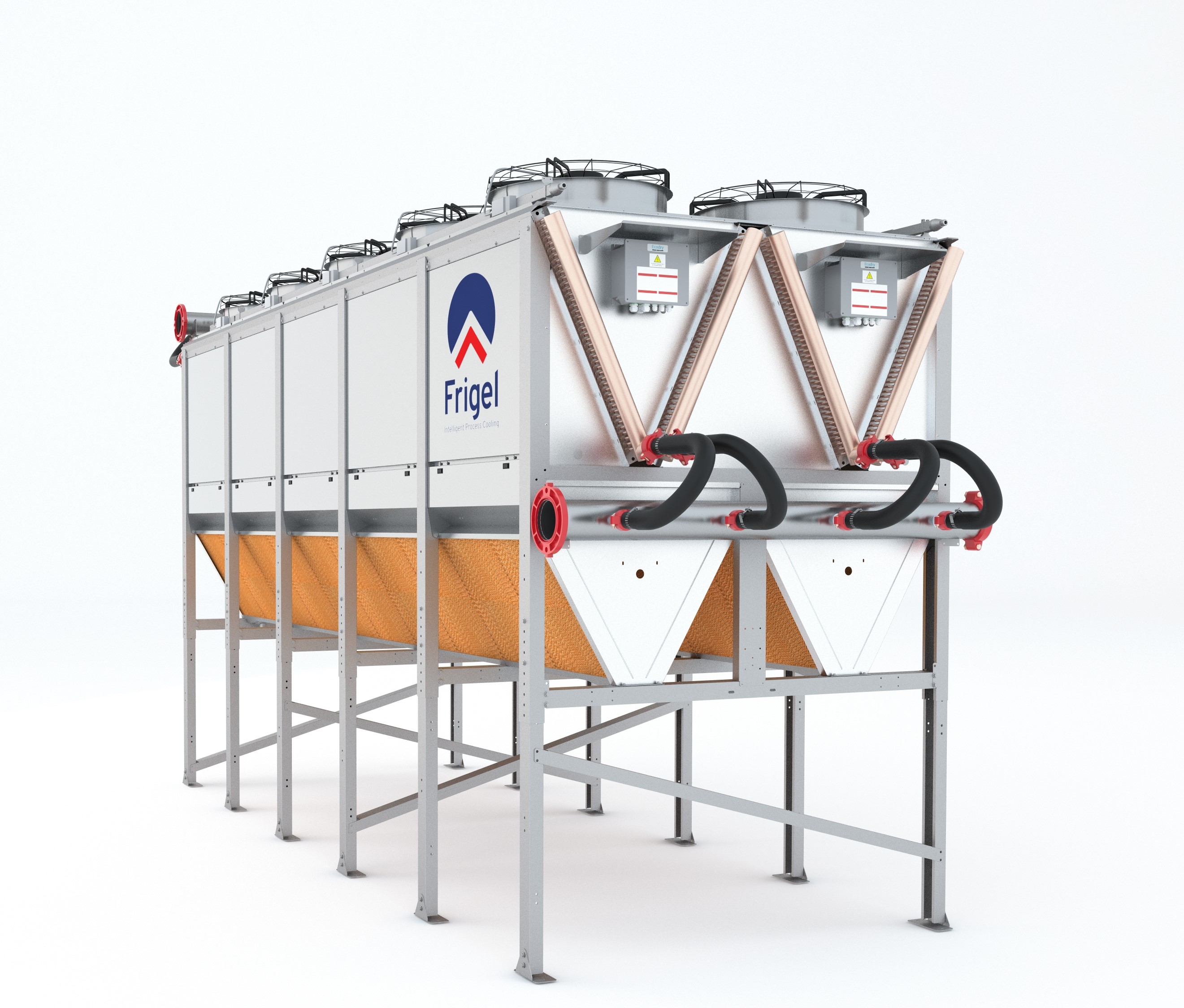
Frigel’s Intelligent Process Cooling systems are designed to create better processes for heat treating operations and provide a unique, flexible solution. The solution combines the use of its internationally patented closed-loop adiabatic fluid cooler with small, dedicated chillers to maximize opportunities for free cooling while ensuring consistent and reliable process cooling temperatures. The closed-loop adiabatic fluid cooler operates outside of the facility, with chillers located near each work cell or process. This approach allows for greater flexibility as individual process cooling needs change.
As a closed-loop system, it requires fewer resources and creates additional opportunities for free cooling capabilities. Water consumption is greatly reduced as opportunities for evaporation are removed. Water consumption is lowered by as much as 95% when compared to an evaporative cooling tower. The closed-loop system also prevents process cooling water from being exposed to the outside air, reducing the need for chemical treatments and additional filtration efforts.
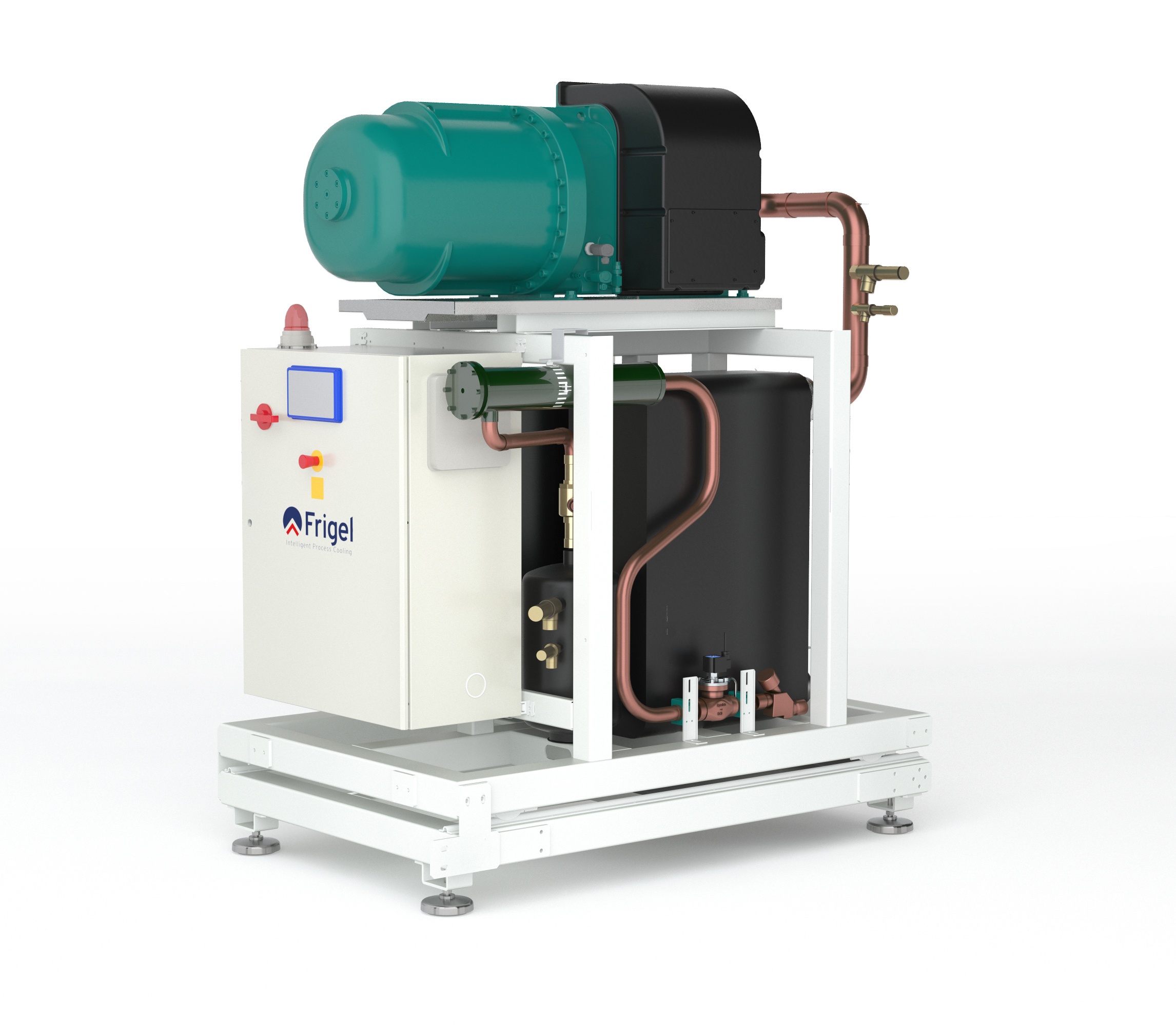
Frigel 3FX chiller
When compared to an evaporative cooling tower, chemical use can be reduced by as much as 40%, appealing to strict municipal water quality regulations while improving system reliability and uptime. Maintenance issues are also drastically reduced in comparison to open-loop systems. Contamination, corrosion, and deposits are all threats to machine performance. By reducing opportunities for cooling coils to interact with moisture, and cooling water exposure to the open air, maintenance-intensive issues are lessened. As a result, production uptime is optimized.
The closed loop-adiabatic cooler system also allows for greater free-cooling opportunities. When ambient conditions are appropriate, localized chillers are bypassed. Instead, heat is transferred to the air via copper tubes in the adiabatic chamber of the fluid cooler, and the cooled water is returned to the furnace vessel. Meanwhile, localized chiller compressors are automatically shut down, saving energy and reducing costs. Working together, the closed-loop adiabatic cooler system and localized chillers are able to provide cooling water temperatures at a wider range of ambient conditions, allowing greater flexibility throughout the heat-treating process.
Additionally, an Intelligent Process Cooling system provides a modular solution. With the fluctuation of job demands and shifting job requirements, the system can expand to fit each unique process cooling need. The use of dedicated chillers allows work cells to be self-contained, reducing disruption and downtime as new process cooling requirements adapt and develop with business growth.
Applying the Intelligent Process Cooling System
At the East Coast manufacturer’s operation, a Frigel Ecodry internationally patented closed-loop adiabatic fluid cooler operates outside the facility. The Ecodry unit is used in combination with dedicated Frigel 3FX water-cooled chillers inside the facility to maximize opportunities for free cooling while ensuring consistent and reliable process cooling temperatures.
At the alloy manufacturer, the Intelligent Process Cooling system installed includes an Ecodry fluid cooler with a patented adiabatic chamber and several water-cooled chillers.
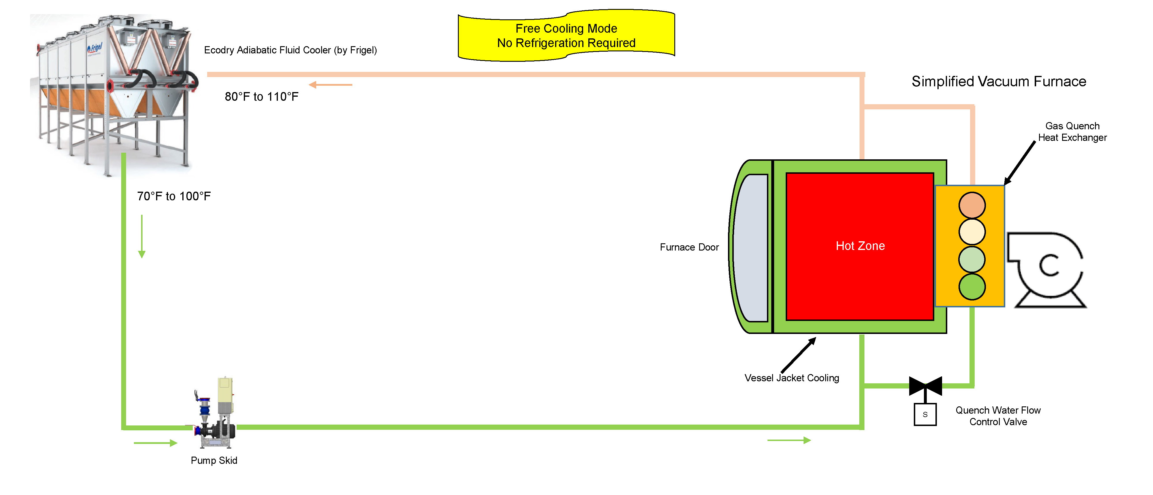
Throughout the year, this system leverages free cooling when ambient conditions permit (see Figure 1). For this manufacturer, the installation location provides ambient temperatures that are quite mild, reducing the necessity for localized chillers from approximately the beginning of October to the end of April. Instead, process cooling water transfers heat to the ambient air via the copper tube and aluminum coils in the adiabatic fluid cooler. Once cooled, water travels to the pump skid, then returns to the furnace vessel where it cools the furnace jacket, furnace door, diffusion pump, and heat exchanger.
Figure 1. The Frigel Intelligent Process Cooling system leveraging free-cooling opportunities.
While the furnace is in processing mode, process cooling water runs between the shells of the vacuum, cooling the inner walls, furnace jacket, furnace door, and diffusion pump. This ensures the furnace exterior maintains a safe temperature and the diffusion pump is able to sustain necessary atmospheric pressure within the furnace vessel. Following the completion of the processing cycle, the quench water flow control valve sends process cooling water to the heat exchanger, decreasing furnace vessel temperatures to the desired temperature for part handling and extraction.
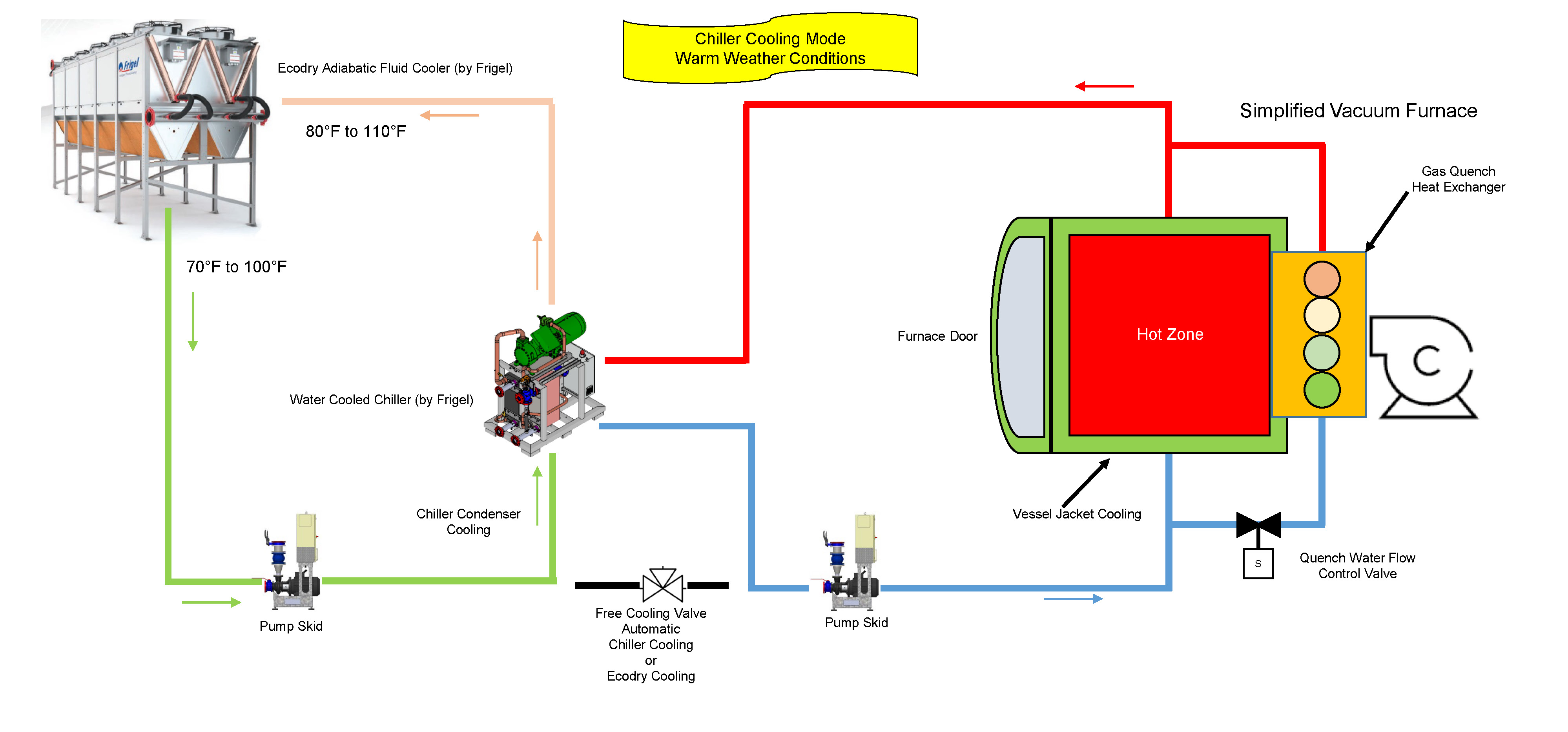
Existing water-cooled chillers supplement the cooling process during the rest of the year when set temperatures can no longer be maintained with the use of free cooling (see Figure 2). When temperatures are at their highest, the water-cooled chillers generate the 70°F coolant and the heat is transferred to the Ecodry loop via the chiller condensers. From there, the chilled water travels to the furnace vessel, cooling the furnace components. Once the water has passed through the process, it returns to the adiabatic fluid cooler, and the water-cooling process begins once again.
Figure 2. The Frigel system leverages chiller cooling mode in warm weather conditions.
If and when ambient temperatures exceed 85°F, the adiabatic chamber of the fluid cooler initiates the spray system to lower incoming air temperatures closer to the wet-bulb temperature. By doing so, the coolant is lowered to a temperature that maintains reliable, efficient operations.
Operational Savings of $80,000 Per Year and More
By leveraging a closed-loop system with an adiabatic chamber, the alloy manufacturer achieved benefits that weren’t possible with traditional technologies. Chiller run time is in the 1,500 hour-per-year range and adiabatic cooling is required less than 400 hours per year. Compared to an evaporative cooling tower and water-cooled chiller system, water use has been reduced by 95% and electrical energy costs have been reduced by 60%. Increased efficiencies and reduced water consumption have resulted in operating costs that are dramatically less than any other system. In total, the plant saves over $80,000 per year with the Frigel system.
For this manufacturer, an alternative solution to traditional process cooling technologies was the only viable option. High costs drove innovation and a need for a better approach. Frigel’s Intelligent Process Cooling system, leveraging the capabilities of a closed-loop adiabatic system and localized water-cooled chillers, allowed for greater operational flexibility while reducing costs and maximizing efficiency—providing the manufacturer with a better process cooling solution.
About the Author
Gary Burgardt, Frigel North America’s market development manager, works closely with prospects and customers to ensure every Frigel process cooling solution delivers measurable results based on each company’s unique processes and business goals. In addition to expertise in Intelligent Process Cooling, Burgardt leverages 30 years of experience in process cooling across a wide range of industries to assist customers at every stage of the planning and buying process.
A German developer and provider of 3DMP metal 3D printers and technology recently announced that the company will open its first U.S. manufacturing facility in Danville, Virginia.
Gefertec LLC will introduce its 3DMP® technology, based on modern arc welding, for the production of metallic parts.
Andrea Clark, president of Gefertec, LLC
“Gefertec is excited to announce the opening of our Danville—Pittsylvania County location as our first U.S. location for our 3DMP® additive manufacturing business,” said Andrea Clark, president of Gefertec, LLC.
Tobias Roehrich, CEO of Gefertec GmbH
“This is in alignment with our long-term commitment to Danville and the Institute for Advanced Learning and Research, and we are excited to expand our business to the U.S.,” said Tobias Roehrich, CEO of Gefertec GmbH. “Danville has been chosen for its excellent business and community support and its involvement in the advanced manufacturing sector.”
This article was written by Dr. Vadims Geza, chief scientist at CENOS. More information on CENOS Platform can be found here.
Induction is becoming an increasingly popular choice for heating steel billets prior to forging due to its ability to create high heat intensity quickly and within a billet, which leads to low process-cycle time (high productivity) with repeatable high quality, occupying minimal space on the shop floor. It is more energy-efficient and inherently more environmentally friendly than most other heat sources for steel billets.
In this article, the author demonstrates a simulation example on how to optimize a progressive induction heating system for a steel billet. The method used is CENOS Platform, a 3D simulation software which focuses specifically on induction heating and uses open source components and algorithms.
CENOS platform is capable of simulating various types of induction heating for forging. It is possible to simulate both static heating and progressive heating where the billet is moved through the coil with constant velocity. In accomplishing this simulation, coil design is not a limitation: both single coil and multi-coil are possible to simulate. Besides the coil, it is also possible to simulate any material and frequency.
The functional performance of the software
CENOS is a finite element method-based, computer-aided engineering desktop software for 2D and 3D physical process simulation and computational modeling of induction heating, induction hardening, brazing, annealing and tempering of steel, aluminum, copper, and other materials.
The simulation process consists of three steps:
Choose the workpiece geometry (from built-in templates or create your own CAD file).
Define induction heating parameters (frequency, voltage, time, etc.).
Run 2D or 3D simulation of your choice.
At the conclusion, results like temperature and magnetic field are displayed in 3D renderings, plots, and more. Apparent power, induced heat, and inductance are logged into an Excel file.
3D Simulation example—comparison of two heating systems
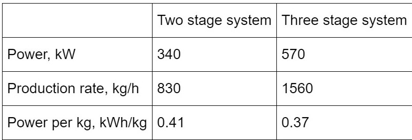
In the simulation, two systems under consideration—two-stage and three-stage systems—in the progressive heating of the billet. The target for the simulation was to reach 2192°F (1200°C) ± 122°F (50°C). To check both systems, the user has to create set up for both of them, set physical parameters (material properties, frequency, current, etc.), and start the simulation.
After the simulation is done, the user will have access to different output variables, including:
Temperature distribution
Current density and Joule heat distribution
Magnetic field lines
Total, reactive and apparent power
Inductance of the coil
Coil current, voltage
In our example of billet heating, it is possible to compare both cases and the output.
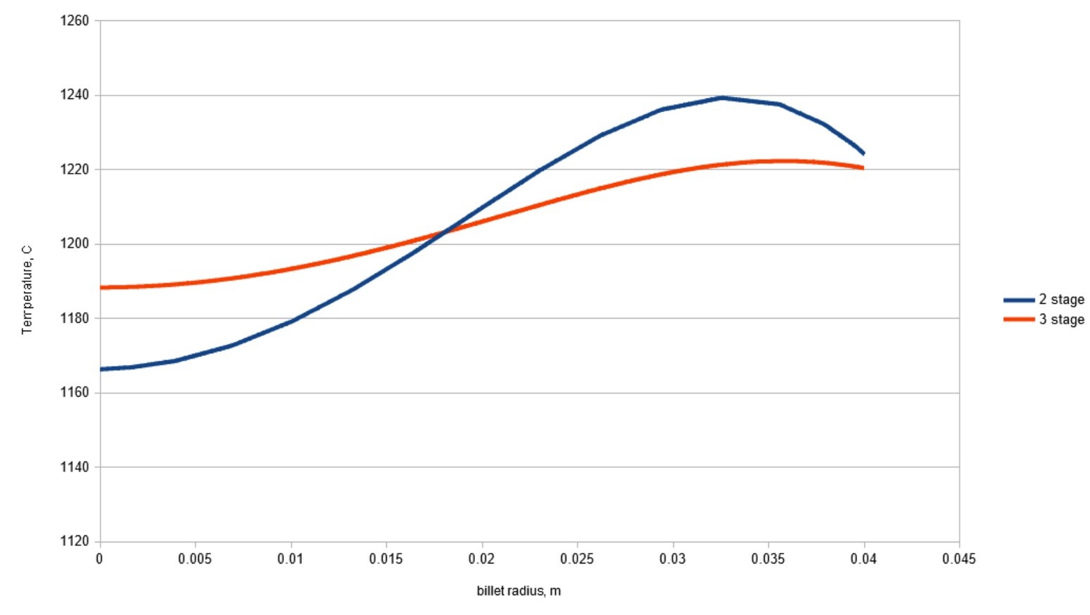
It is observable how a three-stage system can decrease power consumption and increase the production rate for this specific case. It is also possible to plot the distribution of temperature, Joule heat, magnetic field, etc. Resulting temperature distribution in the billet across the radius is shown in Figure 1. As can be seen, better temperature homogeneity is obtained in the three-stage system.
Figure 1. Temperature distribution along the billet radius at the outlet of the heating system
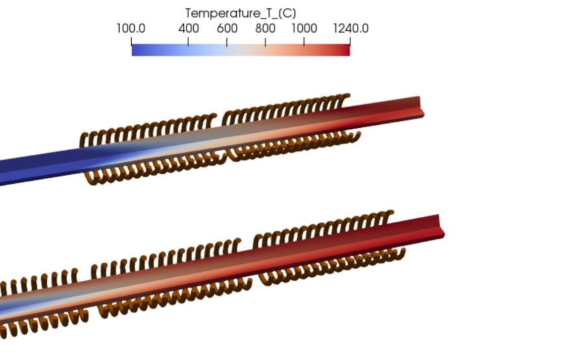
Figure 2. Temperature distribution in the long billet during scanning (progressive) induction heating.
Figure 2 shows how different systems lead to different temperature distribution. In the two-stage system, the temperature required for forging is reached with shorter coils, thus also with smaller scanning speed. This leads to worsened temperature uniformity and smaller production rates. On the other hand, the three-stage system heater gradually increases the temperature of the billet and the resulting temperature difference between core and surface is smaller.
Platform users are free to change all the input parameters and assemble the system of any number of stages required for their process.
Should the same system need to be used for scanning of shorter billets where end effects play a more significant role, it is possible to set up a simulation with a moving billet. An example of temperature dynamics in such simulation are shown in GIF images below:
A simulation with a moving billet in a two-stage system.
A simulation with a moving billet in a three-stage system.
Simulation helps make better decisions for production set-up and planning
As demonstrated in the simulation example, it is possible to compare two different systems and get results. The scope and variety of different simulations are unlimited; it all depends on what problem the user wants to solve:
Dr. Vadims Geza
Heating system design—to optimize induction heating performance, improve product quality, and avoid unpleasant surprises related to subsurface overheating
The selection of power, frequency, and coil length in induction billet heating applications
The selection of right forging temperatures for plain carbon and alloy steels to avoid possible damage by incipient melting or overheating.
Main Photo Image via CENOS, courtesy of efd-induction.com


 Discolored Part—Who’s to Blame?
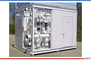
 AMS2750 Is Golden