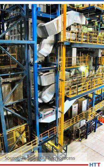
European manufacturer thyssenkrupp Steel Europe AG (tkSE) is revamping burner technology at their continuous galvanizing line located in Bochum, Germany. This modernization measure is an important cornerstone in enabling thyssenkrupp Steel to produce high-strength steels (AHSS) in Bochum in the highest quality and with increased production capacity for further use in the automotive industry.
thyssenkrupp FBA7 in Bochum, Germany
In order to meet market requirements and reduce both emissions and energy consumption, Tenova LOI Thermprocess will ensure that the furnace will be equipped with new burners that meet even highest requirements by targeting the lowest possible NOx-emission levels (lower than 140 mg/Nm³ (@3%O2 reference)) during production. In addition, the heating system will be upgraded in order to increase the target strip temperatures to > 900°C.
This is the third consecutive modernization order that this sister company to North American engineering company, Tenova Inc., received for the continuous galvanizing line in Bochum.
Plant in Bochum, Germany
With an annual production capacity of 540,000 t of high quality galvanized steel it is one of the core production lines of thyssenkrupp Steel Europe for the production of car body parts and AHSS-steels.
The line was commissioned in 1992, and since 2014 major parts have been upgraded with the latest technologies. In the first phase, the pre-heating and over-aging sections were modified to improve the annealing cycle in over-aging regarding larger heating capacity and improved temperature homogeneity. The energy recovery in the pre-heating section has nearly doubled and therefore the carbon footprint of the line was significantly reduced.
In 2017, a major step towards production of AHSS was realized through a substantial revamp of the fast cooling section. A new set of nozzle boxes, fans and heat exchangers were added to the existing equipment. The system is designed for highest heat transfer coefficients and lowest strip vibrations, even with enlarged strip length without roller support.
Sascha Bothen Head of Sales LOI Group
"The modernization step that is now pending is important in order to meet our customers' upcoming requirements for hot-dip galvanized materials," explained Dr. Carsten Groß, team leader of FBA7 at thyssenkrupp Steel. "We are also relying on Tenova LOI's experience and expertise in the field of burner technology for this project. The upgrade of our FBA7 is part of the modernization strategy at the Bochum site."
"Together with tkSE, we developed a well-defined modernization strategy with intense R&D effort in different steps," said Sascha Bothen, head of sales LOI Group. “This project proves that innovative revamping solutions can give an economic and technological benefit even for plants that have been in operation for a long time.”
Indian manufacturer in the defense and aviation sector TATA Advanced System Ltd. (TASL) will receive a solution heat treatment line. It is dedicated for the aviation industry and will meet the requirements of the latest aviation (AMS2750F) and material (AMS2770) standards.
This order, the third of its type from North American manufacturing parent company SECO/WARWICK to TASL, will be the largest production line for aircraft skins in the history of both companies. The equipment will be used for the production of aircraft skins, empennage and center-wings boxes. The line includes a rapid quench VertiQuench® electric furnace (drop-bottom type), mobile quenching tank, rinsing tank and additional equipment including a chiller and loading baskets.
Piotr Skarbiński Vice President of the Aluminum Process and CAB Business Segments SECO/WARWICK Group Source: SECO/WARWICK
The working zone of the furnace is L7500 x W3000 x H3000mm, with the capacity to process huge sheets of aluminum. Such a large working zone reduces the number of joints in the skin. The line, as designed, will meet the client's requirements, ensuring a guaranteed +/- 5°C load temperature uniformity, load cooling in either a polymer or a water quench, and will remove the polymer sediment remaining after quench. Additionally, the system can be used for artificial aging in the furnace.
Abhishek Paul, manager and head of supply chain management of TASL said, "The new line, apart from its size, will meet a number of guidelines that will allow us to produce the highest quality airplane components that will meet the expectations of our final customers - a vast portfolio of OEMs and Tier-1s in the aerospace and defense industry. We are also confident that [the company] will be able to meet the project timelines and handover the line well within our project timelines."
"For us," explains Piotr Skarbiński, vice president of the aluminum process and CAB business segments at the SECO/WARWICK Group, "this continued cooperation directly means that the client is satisfied with the quality and efficiency of [our] equipment, services and our partnership. We hope that this partnership will continue into the future."
Heat TreatToday publisher Doug Glenn talks with Mark Hemsath about hardening basics. Mark was formerly the vice president of Super IQ and Nitriding at SECO/WARWICK, and is now the vice president of Sales - Americas for Nitrex Heat Treating Services Learn all about the what, why, and how of hardening. This episode builds upon the first conversation in Part 1.
Below, you can either listen to the podcast by clicking on the audio play button, or you can read an edited transcript.
The following transcript has been edited for your reading enjoyment.
Doug Glenn (DG): We're here talking about hardness, as it pertains to the metals world, metallurgy, and things of that sort. First off, Mark, welcome back.
Mark Hemsath (MH): Thanks, Doug, it's nice to be here.
DG: For the record, we're recording this thing right before Thanksgiving, the day before Thanksgiving, so we've got turkey on the mind here. I've known Mark for many, many years, in fact, I would say a couple of decades now, when he was with other companies and doing other things. He's a very well-rounded person in the industry. He's able to speak intelligently about a lot of different things, including surface hardness, through hardness and that type of stuff.
Last time, we talked about what hardness was and why it's important. Afterwards, you and I had some conversations and there were a couple of things I think we wanted to supplement onto that first episode. One of those things had to do with hardness testing. Throw out what you were thinking about that.
MH: I think on testing, the point here is that there are many scales for testing because we have many different types of material with different hardness. When we start getting into some of the other materials, it changes a little bit. In the steel realm of things, the most typical is to use a diamond tip weight to try to indent the material. Based on the pressure it takes, we get a reading. For instance, a very thin layer may require a different type of test because one style of test may not be set up to measure such a thin hardness. This is typical in something like nitriding where you have a white layer. Different types of testing methodologies – there is the Brinell, Vickers, Rockwell and Newage hardness testers, and there are a lot of other things out there, as well. In general, we are trying to test the surface hardness and then also the hardness as it traverses through the material.
DG: The other thing that you and I were talking about was other materials besides steels that were hardenable.
MH: I'm not an expert on aluminum, but one of the materials that we talked about is aluminum, and quite frankly, SECO/Warwick has a separate division just dedicated to aluminum because it is different. Let's take a look at aluminum first. Aluminum is actually rather soft and has many other benefits. It is very commonly used in aerospace and companies like Tesla are using it today, almost predominantly, for their cars. Just like in steels, it can get harder by using alloying elements. Most common alloying elements are copper, manganese, silicon, magnesium, zinc and lithium. Hardening is typically by a precipitation or age hardening. Tempering is also very common. So, not all aluminum alloys can be heat treated, per se, but as I was mentioning, it is a whole different world and it requires a whole different set of expertise because it is kind of a unique metal.
DG: How about titanium?
MH: Titanium is an increasingly popular alloy. It is expensive and it has very high strength to weight ratio. It is almost as light as aluminum but much stronger and also has great resistance to corrosion. Titanium can be alloyed to add properties to the metal and it can be nitrided at higher temperature making a very thin, hard layer that is gold in color, something that I've done a little bit of in the past.
On of the other materials that you asked about are stainless steels, and this is also a whole different breed. Recently, in the last 5 – 10 or so years, surface hardening is being applied with great success and it is actually done at low temperatures to make a very hard surface and still retain the corrosion resistance. When you harden stainless steels via nitriding at the higher temperatures, you do get high hardness but you lose corrosion resistance. They've made quite a bit of inroads at the low temperature end of things, so called S-phase hardening. Certain stainless steels, martensitic stainless steels, are actually hardenable by heating and quenching. Those have, commonly, 11 – 17% chromium and no nickel and they have a higher carbon. Austenitic stainless steels, typically at 300 series with nickel, do not harden by heating and quenching. These steels, as I mentioned, can be surface hardened. Ferritic stainless steels, which is another breed, are commonly a lot of the 400 series stainlesses have 10 – 30% chromium and they do not harden by normal means. Then, we have some special so-called alloy 17-4 PH and some of the other ones are hardenable by aging. So, I wanted to go through some of that. There is a lot there. But just to discuss all of the variety of different steels out there.
DG: Let's dive into these five different hardening processes, which we want to talk about, to give our listeners a little better sense of exactly what the process is and how they might differ from one another. The five we're going to cover are carburizing, nitriding, carbonitriding, FNC, or ferritic nitrocarburizing, and LPC, meaning low pressure carburizing. Let's go back and just start with, probably, what I think, is the most popular or common one, which is carburizing. Do you agree?
MH: Yes, I would tend to agree, especially by pounds.
DG: First off, what is it? We covered this last time, but just briefly, let's talk about what carburizing is.
MH: Very briefly, carburizing is the addition of carbon which adds hardness to the surface and, as I probably mentioned before, it needs to be done at elevated temperatures. The higher the temperature, the faster the process.
DG: Basically, break it down. How's it done? What's the temperature? What's the atmosphere? What are the times? General things like that.
MH: Typically, it's done above 1600 degrees F, which is the austenitic temperature range, and more commonly done at 1650 – 1750 F, which is 900 – 950 C. In the old days, they put charcoal powder, which is a carbon, near the steel or maybe in a box, and they heated it and that's how they got carbon. They actually got carbon monoxide gas to form at high temperature and got it to go into the steel. This will actually crack the charcoal and give you the gas. Some people still use this, especially if they've got some very big odd shapes; it's the only way to do it. Somewhat, it is done in other countries, but not as much here.
There is also obviously the gaseous form which is called gas carburizing. That is typically done with carbon monoxide gas, which is typically created from cracking natural gas or using a nitrogen methanol. For endothermic gas, it's basically about 40% nitrogen, 40% hydrogen and 20% CO. In order to increase the carbon content of that gas, people will inject a carbon containing gas like propane or natural gas, etc.
One other method that is still in use is salt bath. It is also somewhat common and here they use a sodium cyanide (NaCN). Basically, most of it being done today is with gas carburizing.
DG: As far as the actual materials? I assume most of it's going to be your steels being carburized?
MH: Yes. Virtually any steel or alloy can be carburized to some extent if it has iron in it. Iron carbides will form. Mostly less expensive steels are done. The so-called low carbon, low alloy steels are typically the ones that are most frequently carburized to get high surface hardness and because they kind of like the core properties that come with it.
DG: Equipment. You already hit on this some, but obviously for salt bath, which you mentioned, you're going to have a salt bath piece of equipment to do it. Gas carburizing is obviously done just inside of an atmosphere furnace, in some capacity, I assume. Can it be done continuous and/or batch?
MH: Yes. The most popular is batch. The integral quench furnace, which is usually an in-and-out furnace where you have endothermic gas both in the vestibule where you put it where the quench oil is. Then you go into the furnace, you do your hot temperature carburizing in the same gas, and then you come out hot and you're protected and then you go into the oil quench, and everything is within that atmosphere. That's the most common. But, as you mentioned, continuous is very viable. The only issue with continuous is it's pretty high production and it's usually the same process over and over. That way you can maximize the use of your quench. Because quenching might only be 20 – 30 minutes tops, whereas the carburizing cycle might be 8, 10 or 12 hours, you're not using that quench very often. Continuous will allow you to use a quench much more frequently and that quench might be fairly expensive, so that makes sense for doing the same parts over and over.
DG: Right. If you've got super high production, that would be the way to go. And, it is probably notable to point out here, that quenching is an important part of the carburizing process. This is not true with some of the other surface modification stuff we're going to talk about down the road, correct?
MH: Yes. Quenching is usually done right afterwards, to save money and to make it economical. That's not to say that there aren't many people, like in press quenching, that will actually carburize it, slow cool it and then heat it up again and then individually quench each part. There are also some benefits to grain growth. If you've got a very deep case, that carburizing might cause some growth in your grains. If you slow cool it and then heat it up quickly again and quench it, you'll transform all that back to the properties that you want. But, yes, typically all done together.
DG: Can we carburize using induction technology?
MH: I'm not familiar with carburizing. . . Induction is typically heating the outer surface and cooling it very quickly and keeping that very hard and then the core will still maintain its property. That's a thermal surface engineering process induction. I had an old engineering friend of mine, metallurgist expert, PhD, who calls it surface engineering or thermal chemical surface engineering, because we're using both a chemical process and a temperature process.
DG: Anything else notable on carburizing before we move on to nitriding?
MH: The only thing is the alloying elements are common in steels. I mentioned before low alloy steels and high alloy steels. Alloying elements common in steels are nickel, silicon, chromium, manganese and molydenum. Silicon and nickel are less prone to absorb carbon, whereas the carbon potentially atmosphere is increased with elements like chromium, manganese and molydenum which form more stable carbides than iron. Alloying elements can adjust the ability to carburize.
DG: That's the basics on carburizing. Let's move on to nitriding. If you can, Mark, as we plow through this, maybe draw a bit of a comparison on, for example, temperature ranges and maybe cycle times and materials, and things of that sort. So, what about nitriding?
MH: Nitriding is a process where nitrogen atoms are diffused into the steel surface. I believe that nitriding is more complex than carburizing because hardness, and the types of nitrides created, are dependent on a number of different factors. So, depending on the process, either ammonia is used or an excited nitrogen atmosphere via a plasma generator can diffuse the nitrogen into the steel surface. What's common with nitriding is it's done at a lower temperature. The diffusion of nitrogen is a time and temperature dependent process, so the higher you take the temperature, the faster the process will go. But, it's still performed at much lower temperatures than carburizing. It's actually done in the ferritic range and not in the austenitic range, typically, 915 degrees Fahrenheit up to just under 1100 degrees Fahrenheit which is 490 C to 590 C.
Nitriding is a process where nitrogen atoms are diffused into the steel surface. I believe that nitriding is more complex than carburizing because hardness, and the types of nitrides created, are dependent on a number of different factors.
DG: You're talking 500 – 600 degrees F, roughly, lower temperature than carburizing?
MH: Yes.
DG: That's the temperature range. Obviously, the atmosphere is different because we've got nitrogen as opposed to carbon, but how about process time?
MH: We talked about the temperature. Obviously, if you're at the higher end of that temperature, you can go a little faster, but nitriding has been known to be slower than carburizing, and it is. The diffusion process is slower. Gas nitriding and plasma nitriding are the two main processes. There is also ferritic nitrocarburizing, which is a form of nitriding with salts. But gas nitriding uses ammonia as a nitrogen donor and plasma nitriding uses nitrogen at a partial pressure with a plasma excited atmosphere. Nitrogen creates iron nitrides in various forms in the white layer as either, what we call, an epsilon layer or a gamma prime layer. In some instances, people don't even want that layer, they only want the nitrogen to go into the steel and create nitrides with some of the alloying elements. This is what we call the diffusion into the alloy into the steel into the alpha.
DG: What about case steps between carburizing and nitriding? If you want a deeper case step do you tend to go carburizing or is there a difference in the case depth actually?
MH: It is much more possible to do a deep case step than carburizing. You can basically keep sending it in there and, if you can go a little bit higher temperature, you can get some pretty deep case steps with carburizing. The difference between the nitriding, is that it's a different process. It's a lower temperature process so it's a little bit slower, but you get a pretty hard case with the right alloy with the nitrided case. In many instances, you can get a pretty similar performance of the part, or something that performs very well, with maybe only one-third of the case.
DG: When we talked about carburizing, we talked about materials that were 'carburizable'. How about in nitriding? What materials are easiest to be nitrided and are there some that we really can't nitride?
MH: Nitriding is kind of opposite from carburizing. Most people will carburize the more low alloy or plain steels, whereas in nitriding, we really want to deal with alloy steels that have alloys in it that will be friendly to absorbing nitrogen. Now, on plain hardened steels, you can get the white layer on there, but you're basically limited to just the white layer for your surface engineering, and you don't get much depth, depending upon what type of alloying elements you have.
DG: Mark, talk for just a second about this white layer in non-technical terms, if you don't mind. Is it, simply, the accumulation of nitrogen above the 'surface' of the metal? What is that white layer?
MH: No, it actually reacts with the metals in the surface layer. Because the surface is being hit with a lot of nitrogen, the reactions there will create what we call a white layer where there is a lot of nitrogen activity and those are iron nitrides. They also will get some carbon that will react in there. That's a very hard layer, somewhat brittle; it is resistant to corrosion and it also has very low friction property. A lot of people want that often but when you're going with the higher alloyed steels, there are some applications where you don't want that, let's say, bearing types et cetera where you don't want any small parts that could come off. The white layer is prone to chipping or coming off, so you wouldn't want that in a bearing, because it's very hard and if it comes off, it can cause problems with your bearing.
DG: I assume, with all the modern day technology and whatnot, we're able to control that white layer and/or depth of nitriding layer through your process controls and things of that sort.
Leszek Maldzinski Professor at Poznań University of Technology Project Leader and Scientific Adviser at SecoWarwick
MH: Yes. Nitriding has been around a long time, but one of the problems that they had was controlling the white layer. Because they basically would just subject it to ammonia and you kind of got what you got. Then they learned that if you diluted it, you could control it. That's with gas nitriding. Then plasma nitriding came around and plasma nitriding is a low nitriding potential process. What that means is it does not tend to want to create white layer as much. It's much easier to control when the process itself is not prone to creating a lot of white layer, unlike gas. Now, in the last 10 – 15 years, people have gotten really good at controlling ammonia concentrations. They've really learned to understand that. One of the people who was instrumental in understanding that is the inventor of our zero flow control technology, Leszek Maldzinski. Understanding how you change the ammonia nitriding potential to get the type of steel layers that you want is rather complex, but once you understand it and have the tools, you can craft the layer exactly the way you want it with ammonia gas.
DG: You did talk about the types of equipment that can do nitriding, but just hit on those again.
MH: Gas nitriding is typically done in a retort to safely hold the ammonia and once the gases start dissociating, we also have hydrogen in there. Also, ammonia gas is very noxious and can be deadly, so you need something tight to hold it, and that's why they'll do it in a very tight retort. Plasma nitriding is done under vacuum, partial pressure. You can do that either in a hot retort or a cold wall vacuum type furnace. Those are the two main processes.
DG: If you had a similarly sized carburizing furnace and a nitriding furnace, would you expect that the nitriding furnace would cost more than the carburizing furnace, or vice versa?
MH: Carburizing furnaces are a little more expensive because you have the addition of the quench and you're also at fairly high temperature. Those are two cost drivers in carburizing.
DG: This next one has always been a little confusing for me. Let's see if you can straighten me out: We talked about carburizing, which is carbon. We talked about nitriding, which is nitrogen. And now we go to something called carbonitriding, which sounds to me like the two are holding hands and performing the process. So, what is it?
"It can be confusing because here in the US we call it carbonitriding and we call the form of nitriding that is FNC (ferritic nitrocarburizing), nitrocarburizing. In Europe, I've heard them exchange those names. But, typically, in the US, we call the high temperature process, which is similar to carburizing, we call carbonitriding. The ferritic, which usually means the low temperature, not austentitic, ferritic nitrocarburizing is a low temp form of nitriding and adding carbon.
MH: It can be confusing because here in the US we call it carbonitriding and we call the form of nitriding that is FNC (ferritic nitrocarburizing), nitrocarburizing. In Europe, I've heard them exchange those names. But, typically, in the US, we call the high temperature process, which is similar to carburizing, we call carbonitriding. The ferritic, which usually means the low temperature, not austentitic, ferritic nitrocarburizing is a low temp form of nitriding and adding carbon. Let's go to carbonitriding which is the high temperature version. It's typically done in low or unalloyed steels that have rather low hardenability. Increasing the quench rate is rarely possible, so what we do is we add nitrogen and carbon to the surface to increase the surface hardness substantially. It actually makes a very hard surface. I usually say this is done for the cheaper steels.
DG: Meaning the less hardenable steels?
MH: Yes, and it's done in less alloyed steels, too, because we're just trying to get a thin hard surface on the outside, for whatever application it is.
DG: And temperature range? Does it tend to be similar to carburizing, up in the 1600 range?
MH: It is, but because ammonia breaks down very rapidly at higher temperatures, we like to do this at the lower end of the austenitizing temperature, so in the 1600 – 1650 range, as opposed to the 1700 – 1800 range of carburizing. Now, that means that the carbon transport to carbon diffusion into your steel surface will be slower, but what we're trying to do is we're trying to get both in there, the carbon and the nitrogen to make that very hard, thin surface. And, we're trying to do it quickly, because we want to do it cheaply.
DG: Is carbonitriding kind of an inexpensive way, if you can do it, of carburizing?
MH: That's what I typically look at it as, yes. And, it's possible to do a lot of these parts. Let's say they're stampings or low expense steels. You can sometimes do that also with ferritic nitrocarburizing if you change the steel grade a little bit. There are a lot of different ways of hardening some of these small parts or clips or what have you. Also very common in screws, roofing screws, etc, to get that hard point on there. It doesn't need to be very thick, it only needs to be drilled into the roof one time.
DG: So that's carbonitriding. We talked about temperature ranges. We talked a bit about the steels that we would use for that. Equipment that is being used for carbonitriding? I assume it's more along the lines of the carburizing?
MH: It's virtually identical. It's either gas atmosphere, integral quench batch furnace or can be done in continuous fashion. A lot of people use mesh belts for it, too.
DG: I neglected to ask you this, back on nitriding. No quench is involved there, correct?
MH: Correct. Nitriding has no quench.
DG: But carbonitriding, you're quenching, because it's kind of a cheap man's carburizing.
Anything else we should know about carbonitriding?
MH: Just that steels like 1018, 1022, the low end, there are other ones that obviously can be done, but that's typically what's being used.
DG: Let's go on to the second to last. We've got two more left. Nitrocarburizing, or as it's commonly or often referred to, FNC (ferritic nitrocarburizing), let's talk about it.
MH: Unlike carbonitriding, which is often confused with ferritic nitrocarburizing, FNC is performed at lower temperatures just like nitriding, but it's typically done a little bit higher temperature than nitriding and it's done just below the initial austenitizing temperature which is around 570 C/1060 F, just below 1100 F you can go to if you're equipment is fairly uniform. The reason they do that is because in ferritic nitrocarburizing, you're trying to create white layer, and white layer will be much more aggressively created at higher temperatures and also with higher levels of ammonia.
DG: So, the temperature is the same. Cycles times. Obviously, the atmosphere is predominantly nitrogen with a little bit of carbon mixed in, I assume.
MH: Right. The nitrogen comes from the ammonia, unless it's a plasma type process, but let's talk gaseous ferritic nitrocarburizing first. You can put a carbon gas in. This can be an endogas to get CO, it could be CO2 injected where the CO2 actually will convert to a CO gas, and people have used other gases, but those are the two most popular forms of carbon gas. What that does, again, because we have typically cheaper steels, they don't have a lot of carbon in the surface, so we want to have a little extra carbon there to get that really hard and aggressive epsilon layer.
DG: Equipment to be used. In nitriding, we were potentially using a vacuum furnace, at times. Do we use vacuum for FNC?
MH: Well, FNC, just like nitriding, you don't need vacuum for our nitriding furnace, we use vacuum purge. Because we want the vessel retort to be very tight, making it a vacuum capable vessel, means it's, by definition, tight because you don't want ammonia to leak out. But, for FNC, people have done this in any number of ways. For example, bell furnace or tip up furnace. I've seen people use their integral quench furnaces, the heating chamber. All you have to do is get to that temperature just below 1100 F, get your ammonia in there and get some sort of carbon gas, and you're going to get a white layer.
DG: I know when we were talking about nitriding earlier, you mentioned that it was done mostly in a retort, one reason was to contain the ammonia, but you don't necessarily need that in FNC? Or, is it pretty common that you would use a retort furnace?
MH: It's commonly done in a retort and commonly done in a pit furnace, but there are people who do it in tip up furnaces. Like I said, there are people who do it integral quench furnaces, people do it continuously. Obviously, when you have ammonia involved, the retort makes the environment that you're standing there much nicer, because you can put the ammonia in the furnace as opposed to around you. Small amounts of ammonia can become choking. I don't like other furnace designs because they're hard to seal.
DG: Anything else you think we should know regarding nitrocarburizing?
MH: It can be done in plasma. It's less common. They typically use a carbon gas like methane, or something, to put in there to try to promote some more white layer. Like I mentioned before, plasma process is typically not very white layer friendly. But if you put that carbon gas in there and increase the temperature, you can get some pretty decent white layer with it in a plasma setting.
DG: Let's move on to the last one: low pressure carburizing. Let's talk about that.
MH: Again, carburizing is the addition of carbon, right? So, the difference here is that when we talk low pressure, it's just like a mentioned before with plasma nitriding, it's done at a negative pressure, less than atmosphere. We call this either low pressure carburizing or vacuum carburizing; it's the same process. This takes place at pressures typically in the 1 to 15 torr range, which is about 1 to 20 millibar range of pressure. If you know one atmosphere is 760 torr, so when we're going down to 1 – 15 torr, we're at pretty good vacuum. Just like with gas carburizing, the higher the temperature, the faster the process. What's unique with vacuum equipment, is that vacuum equipment is typically capable of going to higher temperatures which adds to the speed of carburizing. Now, we didn't discuss the design of gas carburizing furnaces that much, but typically they're gas fired and they have radiant tubes. In the interior of the furnace, the higher temperature you go with the really nasty carburizing atmosphere, it reduces the life of those furnaces substantially, so the people that own the furnaces don't want to go to high temperature. If you can go 100 degrees higher in temperature, like you can with the vacuum carburizing furnace, the process gets much faster. That means higher productivity.
One more feature, as well: the initial carburizing of steel at low pressures is actually faster than gaseous carburizing. The carbon flux of the surface is very high in LPC. The diffusion is the same, once you get into the steel itself, but the flux to the surface is very high. So, shorter, shallower cases are quick, and then, like I said, if you can increase the temperature to increase the diffusion into the steel, on deep cases you can get the cycle less than half.
DG: How long has LPC been around?
MH: Technically, it's been around since probably the late 60s. It had a very slow introduction, in my mind. That's only because they had trouble really getting it to work reliably.
DG: Anything else we should be asking? I assume the steels that can be carburized with LPC are essentially the same?
MH: Yes. Steels are the same. Typically, you want to go a little higher temperature than you would with gas carburizing, so typically above 1700 F and more likely 1750 F – 1850 F. The big difference is with gas carburizing, as I mentioned, we use endothermic gas which comes from natural gas and then with some enrichment, here the carbon carrier is typically acetylene and that's put in at low pressure.
The other thing is, in gas carburizing, they use oxygen probes and they try to figure out exactly what the carbon potential of the atmosphere is. It's totally different with low pressure carburizing. With low pressure carburizing, because you can't really measure it reliably and accurately, we use process simulation software to create the recipes. By being able to model the surface area of the parts and the total weight of the parts and the material, the temperature and the case thickness that you want, the LPC process becomes very reliable and can perform very well.
DG: We've had conversations with folks over at Dante Solutions and they say that this LPC is one of the most read items on their website; people are trying to figure out how to do it and how to avoid the carbides and things of that sort. It sounds like an interesting process.
Anything else we need to talk about on LPC?
MH: I would like to point out that most LPC has been done in vacuum furnaces in the past with high pressure gas quenching. You mentioned it's been around a long time. What they found with high pressure gas quenching is, number one, you can't have a lot of parts in the furnace, which means you have smaller load sizes. In order for the gases to quench, you have to have very high pressure and also, the parts can't be that thick.
Over time, it really hasn't taken off the way I think it should have. And some of the equipment was kind of problematic. There was always done vacuum and oil quenching, but when they combined, and a few manufacturers do this, vacuum and oil quenching with LPC, then the oil quenching allows you basically to use the same steels to get the quench rates and to start to get some heavier loads in your furnace so that you can get the productivity.
This has now driven, what I consider to be, a viable option to gas carburizing. For instance, with our Super IQ furnace, we use a conventional oil quench. It's no different than the standard oil quench that most people use in their integral quench furnace. However, the heating is done in LPC. The difference is, instead of transferring the load in vacuum, which is what a conventional vacuum furnace will do, or transferring it in a hydrogen and nitrogen atmosphere, we transfer it only in nitrogen.
We have found out that there is no added IGO or any other problems with doing that. What ends up happening is you can make a less expensive furnace and you don't have to use vacuum quench oils, which are a different breed- they're not as fast, they're more difficult to wash off and clean off. We think that combination of LPC and standard oil quench makes a very high performing furnace with LPC. So, it puts LPC into a new interest level, in my mind. But, again, you still have to have very reliable simulation software. We have over 10 years of experience putting that software together, so it's very reliable.
DG: Just so the listeners know, we're doing a 3-part series and we're in #2 right now. Next time we are going to talk about some of the more conceptual things regarding nitriding LPC and we're going to even talk a little bit about single piece flow because there's been a demand for single piece flow. We're going to talk about some of the recent advances in some of these systems which we've hit on here just briefly.
Mark, I appreciate it. This time, I think we've done a good job at covering carburizing, nitriding, carbonitriding, nitrocarburizing and a little bit on LPC. Next time, we'll look forward to talking with you more about some of these other things.
Doug Glenn, Heat Treat Today publisher and Heat Treat Radio host.
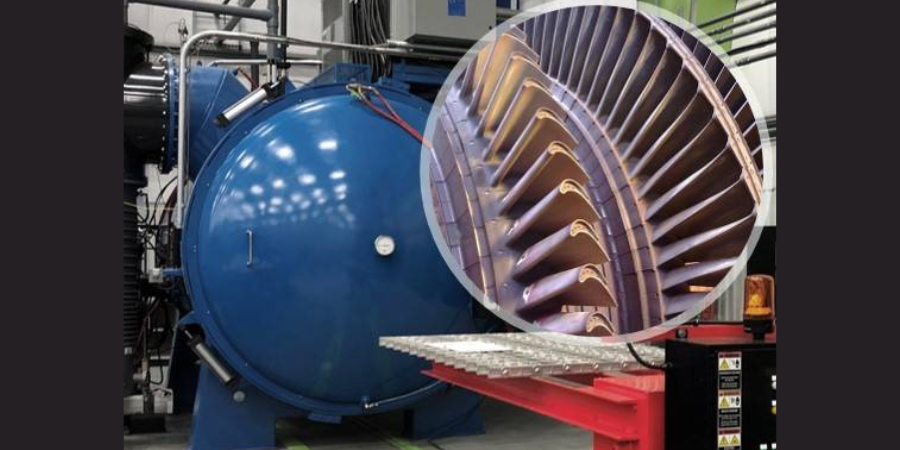
NexGen Advanced Fuel Systems (AFS), a gas turbine component overhaul facility that is a company of Allied Power Group, ordered a new vacuum furnace to help increase their capacity and reduce turnaround time for their heat treating and brazing operations. It is built specifically to heat treat land-based turbine equipment with attention to specific cooling specifications required by the company's clients.
Built by Solar Manufacturing, the furnace features a Solarvac® Polaris Control System and a graphite hot zone accommodating loads up to 48" wide x 48" high x 72" deep. The furnace has a maximum load weight capacity of 6,000 pounds.
The furnace achieves a vacuum level of 10-5 Torr, and reaches a maximum operating temperature of 2400°F. A 300 HP gas fan will allow NexGen to quench a load from 2150°F to 1000°F in just three minutes, using only 2-bar.
Solar Manufacturing Vacuum Furnace Source: Solar Manufacturing
"The interface makes running the furnace easy for operators of all skill levels," states Mark Dion, president of Nexgen-AFS, and the general manager ofAllied Power Group Combustion Technologies. "For furnace installation and operation, Solar provides knowledgeable engineering and support staff. The Solar furnace has a robust design, with some nuances such as stainless steel internals, brass fittings, made in USA valving, and in our case, a beefed up blower allowing super-fast cooling abilities. . . . Nexgen hopes business growth supports purchasing a second Solar vacuum furnace."
What is the most common cause of induction tooling failures? What is essential for the longevity of induction tooling? What is a vital component for induction tooling’s successful performance? This informative article shares the answers to these questions and provides valuable guidance for your induction needs.
This Technical Tuesday is provided by David Lynch, vice president of Engineering at Induction Tooling, Inc. and was featured in the Heat Treat Today’s2021 May Induction print edition. Check out more original content articles in this digital edition or other editions here.
David Lynch Vice President, Engineering Induction Tooling, Inc.
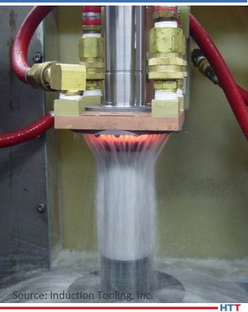
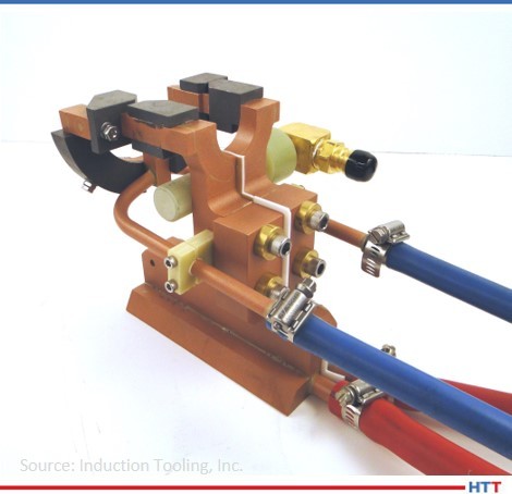
Most induction heat treating applications are challenged with a harsh environment often dealing with high frequencies, high power, heat, smoke, steam, dirt, oil, quench fluid, quench additives, and contaminates. How induction tooling components are maintained in these harsh environments greatly impacts their performance and longevity.
The induction power supply, workstation, and material handling system should all be properly grounded. The work holding system should be level, square, and have proper alignment between the inductor coil and the workpiece for it to be heat treated. Part-holding fixtures should be held to a dimensional tolerance to ensure proper positioning and repeatability with minimal runout. The heat-treating process should include documentation of parameters including positioning (the air gap of the inductor coil relative to the workpiece), scan rates (in/sec), power (kw), frequency (kHz), heat time (sec), dwell time (sec), and quench time (sec). If auxiliary quench lines or nozzles are used, recording positioning data with pictures will guarantee repeatability of the process. Keeping track of quench water temperature, pressure, and flow along with percentage of polymer (aka viscosity) will help ensure consistent results. Keeping track of cooling water temperature, pressure, and flow is important in troubleshooting water cooling issues. The power supply should be routinely serviced and calibrated along with having an active preventative maintenance schedule.
Ball Race Inductors
Inductor coils should be properly designed to not only produce a heat treat specification, but also be of high quality, manufactured from quality materials with maximized water cooling and robust construction. Flux intensifiers should be properly matched to the operating frequency and attached to the inductor coil securely. Teflon insulators should be virgin grade and replaced if damaged or worn. Fasteners, fittings, and hose clamps should be non-ferrous such as brass or 300 series stainless steel. Hoses should be specified non-conductive and rated to meet or exceed supplied water pressure. Epoxies used should be rated for high temperatures and allow for expansion and contraction. Electrical contacts should be silver plated to provide superior contact and prevent oxidation.
Gear Tooth Scan Inductor
Manufacturing inductor coils is a skill that takes years to develop and several more to master. These tools can be made from copper tubing utilizing fabrication techniques with the use of bending fixtures and forming dies. Most tools today are machined from solid, raw materials often with complex geometries. To ensure quality and consistency, 5-axis CNC machining is often used. Thirty to forty percent silver braze should be used for joining the inductor coil components and sealing water-cooling passages. Designs should avoid sharp corners and provide smooth transitions for optimal current flow and minimal stress risers. Computer-solid models, engineering drawings, and process forms following ISO 9001:2015 certified standards guarantee a quality manufactured induction coil.
Ring Bearing Inductor
Inductor coils are precision handmade tools and should be treated as such. Inductor coils should be supplied in a heavy-duty case with packing materials to provide the proper support and protection during shipping and storage. Identification should be clearly marked on the case. Many cases are lockable as theft may be a concern. When inductor coils are removed from service, they should be cleaned with soap and water using a Scotch-BriteTM cleaning pad. Steel wool and steel bristle brushes should be avoided as the steel can imbed into the copper and may cause more harm than good. Once the inductor is cleaned, it should be closely evaluated for signs of wear or damage. If there are any signs of wear or damage, it should be sent out for maintenance or repair so it will be ready for the next use. After tools are cleaned and evaluated, cooling passages should be blown out with air and the inductor should be dry before sealed in the case and put into inventory. Notes and pertinent data related to the inductor can also be stored with it such as the number of parts processed, any modifications made to the inductor coil, and recorded setup data.
All of what was stated above about design and manufacture of inductor coils also applies to bus bars and quick-change adapters. These devices are used between the workstation and the inductor coil to bridge the gap closer to the workpiece. Originally developed for the automotive industry, quick-change adapters can drastically reduce changeover time, often without the use of hand tools. Since these devices are typically kept on the machine for long periods of time, it is important to check the condition and perform maintenance when needed. Scheduled maintenance of removal and cleaning of these devices will exceedingly increase their life. As with inductor coils, soap, water and a Scotch-BriteTM cleaning pad is all that is needed for these items; steel wool and steel bristle brushes should be avoided.
Multi-Turn O.D. Scan & Quench
When installing bus bars, adapters, and inductor coils with a bolted contact, it is extremely important to make sure that each of the mating surfaces are clean and free from debris. When dirt accumulates or ferrous debris is contained between the contacts, severe arcing and melting can occur.
It is also very important to use proper fasteners. For correctly fastening contact surfaces, 300 series stainless steel bolts with heavy brass washers are preferred. The heavy brass washers help distribute the load evenly and help prevent damaging the copper. The bolt threads should be inspected for wear and replaced new if there is any sign of wear or damage. It is also very important to verify that the length of the bolts will properly clamp without bottoming out before tightened. The recommended torque procedure for 3/8-16 stainless steel bolts is to tighten each bolt twice at 35 to 40-foot pounds. Special "break-away" bolts are available that are designed to fail beneath the washer if they are over tightened. This prevents damage to the threaded insert inside the copper contact. The remainder of the bolt can then be removed with pliers. This is much easier and less expensive than having to repair a bus bar contact or workstation transformer.
O.D. Scan with Quench
The workstation contacts, bus bars, adapters, and inductor coils are all electrical components that when energized are a live circuit, often with high power. The inductor coil produces a strong magnetic field used to heat the workpiece. There are also stray magnetic fields in the surrounding area. It is very important that everything in the surrounding area of these components be non-ferrous to prevent them from heating up. Something as simple as a steel hose clamp in close proximity to the magnetic field could heat up, causing a hose to melt, or a hose to come off, preventing water cooling and severely damaging the induction tooling or the induction machine. Steel fittings can rust and contaminate a water system very rapidly, choking the water flow internally and causing premature failure from low water flow. Any support structure to the induction tooling components should be a quality non-porous insulating material. Non-porous materials prevent liquid and contaminates from being absorbed and ultimately may cause a short circuit.
Proper water cooling is essential to the performance and longevity of tooling components. Both the induction power supply components and induction tooling components need to be properly cooled. Most power supply manufactures have a closed loop cooling system requiring deionized or distilled water. Most power supply manufacturers require that the cooling water temperature be maintained from 80 to 90 degrees Fahrenheit to prevent condensation inside the cabinet and on the circuitry. For cooling the inductor coil, bus bars, and adapters, deionized or distilled water is not necessary. Cooling water for these induction tooling components is best to be kept below 70 degrees Fahrenheit. This may require a separate cooling supply. Through laboratory experimentation and real-world production trials, it has been proven that lower cooling water temperatures can drastically increase the life of these components, especially in high volume, high power, short cycle applications.
The internal water-cooling passages of the inductor coil can play a significant factor in performance and longevity. Each inductor design should focus on maximizing water flow while minimizing sharp transitions.
The cooling water supply should come from a clean water source with a filtration unit of 25 microns placed just before it enters the induction tooling components. This guarantees that contaminates are filtered out, which may otherwise cause a low-flow or no-flow condition.
Quality non-ferrous fittings should be properly sized and configured to ensure the hoses are attached correctly to the induction tooling. It is very common to see 3/8" quick-change fittings used for cooling lines and 1/2" or 3/4" quick-change fittings used for quench lines. Using quick-change sockets for supply lines and quick-change plugs for return lines ensures the proper connections are made every time. Color-coding the hoses also helps in identifying water lines. It is very common to see blue hose for supply lines, red hose for return lines, and black hose for quench lines.
Single Shot Stem Inductor
Some inductor coils can be very small, having very limited water-cooling passages due to physical space. With these small inductors, it is even more important to have proper water cooling. In these situations, the use of a high-pressure booster pump may become necessary. These pumps can ensure cooling water continues to flow through these tight passages. Positive displacement pumps can also overcome steam pockets and help prevent vapor locks.
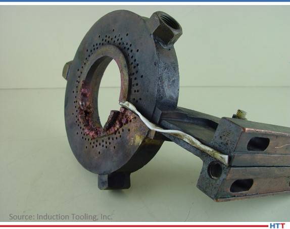
Problems with a cooling system can be detrimental to the performance and longevity of induction tooling components. Contamination in the cooling system can lead to low water flow. Problems with the water pump can also cause a low water flow condition. Then, low water flow can cause a steam vapor lock in the inductor coil leading to a rupture at a braze joint, a rupture through the tubing in a fabricated inductor coil, or a breach in the copper exposing the cooling chamber. Low water flow can also cause laminar flow internally which leads to thermal failure, resulting in exposed surface cracks through to the cooling chamber. Low water flow is sometimes identified by darkening of copper with purple color tones on the cooling return side of the inductor coil.
Wheel Bearing Single Shot Hardening
Induction tooling components cannot survive without water cooling. Symptoms include darkening of copper with purple color tones, melted copper, and catastrophic failure. Catastrophic failures caused by a no-water condition cannot be patched and require a major rebuild or replacement. It is a wise investment to have a flow indicator on the machine that prevents operation if there is no water flow or a low water flow condition.
All of what is stated earlier about the design and manufacture of inductor coils, bus bars, and adapters can also apply to quenches. These devices are used to evenly cool the part after heating to transform the structure consistently. Let’s discuss some of the important details in a quench system such as their design, fitting and hose requirements as well as pumps, filtration, and maintenance.
Quenches should be designed to provide a sufficient amount of quench to fully transform the metallurgical structure as specified. The quench pattern should be a uniform array of holes to quench the part at a proper impingement angle. The volume of water required should be matched with a supply having an inlet to outlet ratio not to exceed 1 in: 2 out. Hoses should be specified non-conductive and rated to meet or exceed supplied water pressure. Fittings should be high quality, non-ferrous without auto shutoffs, which can hinder quenching action and tend to clog more often.
Quenches can be a component that is kept on the machine for long periods of time. It is important to check the condition of these devices and perform routine maintenance. Scheduled maintenance of removal and cleaning these devices will exceedingly increase their life. Soap, water and a Scotch-BriteTM cleaning pad works well, and again, steel wool and steel bristle brushes should be avoided. Having a quench designed with bolted removable quench plates allows easy clean out.
Quench water needs to be filtered and contaminates kept at a minimum to improve performance and increase longevity of induction tooling components. A typical quench filter consists of a stainless-steel filter housing and a 100-microns bag filter. It is also very important to have a system for magnetic particle removal. Magnetic rod filters are available in many configurations, some that install inside the filter housing with the bag filter. Automatic separators are also often used. A low-cost alternative is to install a rubber coated magnet in the quench tank. In a non-ferrous tank, it can simply be dropped to the bottom. In a ferrous tank, it must be suspended to prevent the tank itself from becoming magnetized. All these methods can work, but only if they are properly maintained. A solid preventative maintenance schedule for these filters is essential.
Low Water Flow Failure
When filters are not used or maintained, tooling repairs are required more frequently. Common contaminates found inside quenches include oil dry, metal chips, and chewing tabaco. We see inductor coils come in for rebuild with a heavy patina of dirty, crusty contaminates. These contaminates are commonly a buildup of magnetic particles attracted by the magnetic field generated by the inductor coil. This patina accumulates and can create a short circuit, damaging the inductor coil.
To summarize, contamination is by far the most common cause of induction tooling failures. Water cooling is essential for longevity of induction tooling. Maintenance is essential for the performance of induction tooling. High quality, well-designed, robust induction tooling should be used for best results and consistency. Analyze induction tooling failures when they occur. Troubleshoot induction tooling rebuilds for possible machine issues. Look for methods of improvement with each opportunity. In closing, the best way to improve the performance and longevity of induction tooling components is to have open and frequent lines of communication with your tooling vendor.
About the Author: David Lynch is vice president of engineering at Induction Tooling, Inc. with 36 years of experience and is also the Deputy of the ISO quality system. He has created and developed the system and templates being used today for creating and tracking engineering drawings, job history, rate tracking, and job performance. David holds several design patents, has authored several published articles, and has often presented at technical sessions. He enjoys working closely with customers to develop valued solutions across a wide range of induction heating applications from initial design concepts to implementation, customer support and troubleshooting.
For more information, Contact David at dlynch@inductiontooling.com.
In this month’s column, John Clarke will expand his discussion beyond combustion safety to include the economic issues that are concerns to all equipment owners and operators.
This column appeared in Heat Treat Today’s2021 Induction May print edition.
John Clarke is the technical director at Helios Electric Corporation and is writing about combustion related topics throughout 2021 for Heat Treat Today.
John B. Clarke Technical Director Helios Electric Corporation Source: Helios Electric Corporation
The furnace's or oven’s burner management system (BMS) and its associated components are all that stand between us and an incident. The severity of these incidents ranges from the very expensive — a damaged furnace or oven — to the tragic — loss of a human life. It is a testament to the good work of hundreds of people that combustion system explosions are so rare. That said, the risk to life and property mandates that we revisit this subject frequently, and the risk to profitability dictates we expand our consideration beyond safety to include uptime and quality, as well.
National Fire Protection Association Standard 86 (NFPA 86), or “Standard for Ovens and Furnaces,” provides a standard that is the most common guide to the application of combustion components used in the US. This excellent prescriptive standard reflects the common thinking of people with hundreds of years of combined experience; but it still requires expertise to properly interpret and apply its requirements. It is important to not only understand what component must be provided, but also why.
NFPA 86 is used as a guide for the design of your BMS which includes the various control components to properly monitor the startup and operation of the burner. NFPA 86 also applies to the fuel train, constructed of components that regulate the flow of fuel and air and includes blowers, regulators, valves, filters, and sensors. What BMS and fuel train safety system issues should most concern an end user? An end user must know what it really means when your system is stamped “NFPA 86 Compliant.” To paraphrase Clint Eastwood: The end user needs to know their system’s limitations.
The NFPA 86 standard has been developed to protect life and property, but not production and profits. It is also a prescriptive standard, providing specific guidance to what components need to be applied and in what order. The shortcoming of a prescriptive code is that it must be mostly generic, that is, it applies to types or classes of equipment as opposed to specific applications. Given the variety of burner applications used in industry, it would be impractical to specify every component, order, and wiring for every conceivable process heating application.
Why is this a concern for end users? A specific application may have unforeseen risks or are out of the scope of NFPA 86 . Critical failure modes may be indirectly associated with a burner failure. For example, loss of a process air flow may allow a heat exchanger to overheat before a high temperature limit instrument detects the temperature rise. In this case, the process air flow must be monitored, and the flow or pressure switch monitoring the air flow must be added to the interlock string. This way, the burner will shut off as soon as the air flow failure is detected and not wait for the heat exchanger’s temperature to rise to an unsafe temperature. Another reason to “exceed” the code is that often ovens or furnaces are one element in a much larger manufacturing system. An example would be a continuous paint line, where a failure of the curing oven might shut down an entire facility.
What should an end user do? Ensure the system provided meets the standards and codes, NFPA 86, the Fuel Gas Code (NFPA 54), NEC, etc. This level of compliance is the minimum – and is often not the optimal. Additionally, invite the OEM who built the system to apply their experience and exceed the standards if it provides a more robust system. It may cost a few dollars up front, but it will be pennies when compared to the cost of an incident or, in many cases, an outage.
Encourage your supplier to apply a recognized process to the system review, perhaps a failure mode effects analysis (FMEA) and factor in not only the cost of an incident, but the cost of lost production or quality rejects as well. Consider an independent third-party review – it never hurts to get a second opinion. Review the cost of redundancy, be it online or near online . What is the cost of a second flame rod and flame safeguard when compared to the value of four hours of production?
Next, review the steps to service the system. Look at the mean time to replace (MTTR) a failed component. Has the system been designed to be easily serviced? Are there pipe unions on either side of all critical valves? Where are the spare parts located? What skill trades are required to make the repair? Is post replacement calibration or testing required? And if so, has it been documented?
Ask if the BMS provides a clear indication of the reason for a shutdown. The interlock string, a logical series wiring of critical components where any one component indicating a fault will disable the combustion system, should be monitored in a way where the “first out” or component that will shut down the system, is clearly identified.
Lastly, it is the end user’s responsibility for periodic inspections and equipment maintenance. NFPA 86 prescribes that the BMS and fuel train components are inspected per the manufacturer’s recommendation, but at least once a year.
The annual inspection is a critical step for safe operation but is viewed by many end users as simply a cost. Add to this the relative reliability of most components and we are presented with the ironic risk that maintenance personnel may take short cuts during the periodic inspection. One such person may say, “I always check the low gas pressure switches and they always pass, so I thought, what would it hurt if I skipped the test this year?”
For a more robust inspection, consider adding more value to the process. Combine the safety inspection with an extensive equipment calibration and service: Replace the filters, change the thermocouples, calibrate the control instruments, tune the burner, check the fuel-to-air ratio of the burner, and inspect the BMS components. This adds value to the process and makes it more palatable for the maintenance department.
When the cost of downtime of a key piece of equipment is high, practice the repair, at least on paper. However, if a failed burner shuts down an automotive assembly line, isn’t it worth the time to run actual drills?
In general, most burner trips are the result of a failed sensor, a UV scanner, dirty flame rod, an open thermocouple, or the vibration from an unbalanced fan tripping a pressure switch. In other words, when this type of trip occurs, the greatest cost is lost production, followed by the labor to diagnose the problem and then the cost to replace the component. Generally, the purchase price of the component is far less than the other costs associated with the system trip. Do not be penny wise and pound foolish. Spare parts are a pretty good investment.
If you need the heat from a burner to make your product, it makes sense to not only consider safety, but also plan reduced downtime as well. In the coming articles, we will examine these issues in greater detail, so stay tuned.
John Clarke, with over 30 years in the heat processing area, is currently the technical director of Helios Corporation. John’s work includes system efficiency analysis, burner design as well as burner management systems. John was a former president of the Industrial Heating Equipment Association and vice president at Maxon Corporation.
In preparation for Heat TreatToday's May Induction magazine, here is a best of the web to end your week on.
How do they do it? What happens to metals when they are being induction heated? If you've had experience with heat treating using induction, how does it compare to other forms of heat treatment? This helpful article runs down the basics of induction and includes a video with different phases of the process. Check it out!
"As current flows through a medium, there will be some resistance to the movement of the electrons. This resistance shows up as heat (The Joule Heating Effect). Materials that are more resistant to the flow of electrons will give off more heat as current flows through them, but it is certainly possible to heat highly conductive materials (for example, copper) using an induced current."
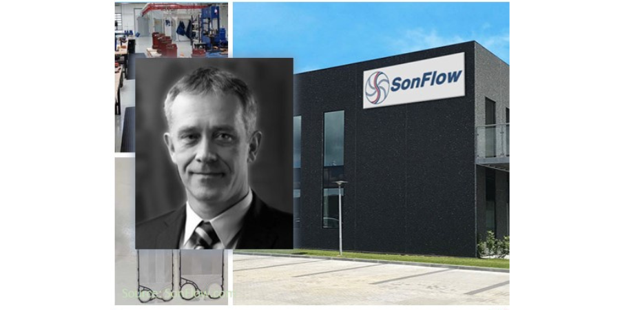
A Scandinavian manufacturer of heat exchangers, SonFlow will receive a vacuum furnace from the parent company of a North American manufacturer for copper brazing adapted to the individual needs of the company's clients. A special nozzle design and electrical penetration assembly will ensure that the device is specific for the production of the latest, high-capacity plate heat exchangers for industrial, HVAC, off-shore and sanitary purposes to be manufactured in the Kolding plant.
Maciej Korecki Vice President of the Vacuum Furnace Segment SECO/WARWICK (source: SECO/WARWICK)
SonFlow is a European manufacturer which has historically been known for manufacturing high-capacity industrial pumps. The company is now expanding into the plate heat exchanger business. Manufacturing state-of-the-art, powerful heat-exchangers has provided the incentive for the plant to purchase a furnace from SECO/WARWICKthat will satisfy the current production challenges associated with the brazing process.
The working area of the device (900 x 900 x 1200) will enable the plant to perform in-house brazing, without the need to outsource work to third-parties. Power savings, one of the pillars of their mission, is ensured by the graphite chamber, and the shortened cycle time is guaranteed, thanks to the vacuum level of 10-3 mbar.
"Years of experience," explained Maciej Korecki, VP of the Vacuum Business Segment at SECO/WARWICK Group, "and the above approach have resulted in developing a special design of the cooling nozzles, optimum for brazing companies. This dedicated solution consisting of the special nozzle design for these radiator applications prevents excessive deposits of brazing residues in undesired areas of the heating chamber. With this design, the risk of damaging the device during the brazing process is eliminated."
Ohio-based aluminum extrusion die manufacturer Youngstown Tool & Die (YTD) continues with their expansion strategy, scaling up value-added nitriding services. The installation of the new nitriding system makes it possible for YTD clients to obtain greater performance results from treated dies.
In the last quarter of 2020, Youngstown Tool & Die expanded withNITREX Canada to incorporate Nitreg® controlled nitriding with the installation of a Nitrex turnkey gas nitriding system, complementing their range of heat-treating services.
Roll-out of the expansion started last summer when YTD relocated to a larger manufacturing facility and made investments in new production and finishing equipment to increase its manufacturing capabilities and meet the growing demand in the USA. As part of the new production, YTD installed a Nitrex pit-type NX-1015 nitriding system that boasts a 4,400 lbs. (2,000 kg) capacity for treating aluminum extrusion dies.
"This is the company’s first purchase of a Nitrex nitriding system and we are glad to be part of their growth strategy," said Jack Kalucki, account executive at Nitrex.
What do helicopter gears and heat treat modeling have to do with improving the bend fatigue performance of low-alloy gear steels? Find the answer in this interesting case study which analyzes the effects on compressive surface stress caused by changing the heat treating process.
This Technical Tuesday is provided by Justin Sims of DANTE Solutions and was featured in the Heat TreatToday's 2021 March Aerospace print edition. Check out more original content articles in this digital edition or other editions here.
Introduction
Justin Sims Lead Engineer DANTE Solutions
Helicopter powertrain gearing can be subjected to tremendous loads during service. The high tensile loads experienced in the root of the gear tooth, combined with the cyclic loading conditions inherent in gear operation, can lead to cyclic bend fatigue failures. To improve cyclic bend fatigue performance, low-alloy steels are often carburized and quenched. The combination of a high carbon case and low carbon core leads to increased strength and hardness in the carburized case, while maintaining a tough core. In this manner, the case resists wear and can carry a high load without fracture, while the core is able to absorb the energy imparted to it during operation.
Besides the increased strength and hardness, the addition of carbon creates a chemical gradient from the surface of the component towards the core. The carbon gradient creates delayed martensite transformations relative to the low carbon in the core and is responsible for imparting residual compressive surface stress. A compressive surface stress can benefit bend fatigue performance by reducing the mean stress experienced during service, effectively offsetting the tensile stress generated by the cyclic loading conditions.
Most gear steels contain enough alloying elements to guarantee a transformation to martensite upon quenching to room temperature from the austenite phase field. It is well known that the martensite starting temperature is significantly influenced by the amount of carbon in austenite at the time of transformation, with higher amounts of carbon generally lowering the martensite start temperature. This means the chemical gradient present after carburizing creates a nonuniform phase transformation, with the transformation starting at the base carbon just below the carburized case and progressing inward toward the core.
As the martensite is formed, the atomic rearrangement results in a volume expansion, causing a tensile stress to form on the surface as the core material pushes out on the surface. As the component continues to cool, the martensite start temperature is reached in the carbon rich case, usually well after the core has transformed to martensite or bainite, depending on the cooling rate. The transformation in the case progresses outward, with the surface being the last to transform. This core-to-surface transformation results in a compressive surface stress since the volumetric expansion created by the martensite transformation at the surface is constrained by the core material.
Because the timing of the transformation to martensite is the main driver in the generation of compressive residual surface stresses, it is possible, to some extent, to control the magnitude of the surface stress by changing the quenching process. Historically, transmission gears have been carburized and quenched in oil. However, as more attention is paid to improving part performance through processing techniques, other forms of quenching have become available that show promise in increasing surface compressive stresses, and thereby improving bend fatigue performance. Of particular interest is a quenching method which utilizes high pressure, high velocity water to quench parts.
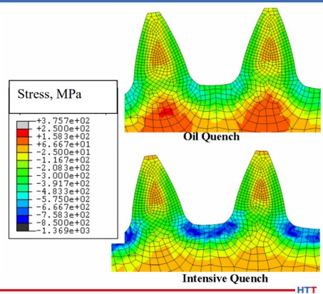
Figure 1. DANTE residual stress predictions comparing a gear subjected to oil quenching and intensive quenching
Known as Intensive Quenching®, the method was developed by Dr. Nikolai Kobasko as an alternative means of quenching components to achieve deep residual surface compression and improve bend fatigue performance.1-3 The technology works by inducing a large temperature gradient from the surface to the core of the component. In non-carburized components, the process has been shown to provide an extremely rapid and uniform transformation to martensite in the surface layers, while the core remains austenitic. This creates a hard shell under extreme compression. As the part continues to cool, the surface is pulled into an even deeper state of compression. As the core transforms, some compression is lost due to the expanding core, but the compression that remains is generally greater than that achieved by oil quenching. 4 – 7
To evaluate the possibility of improving bend fatigue of helicopter transmission gears, a program was conceived to compare the bend fatigue performance of carburized gears quenched in oil versus carburized gears quenched using the Intensive Quenching process. Funded by the U.S. Army, the project was comprised of two phases. Phase One was a proof-of-concept phase, designed to prove that intensively quenched components could outperform oil quenched components in high cycle bend fatigue testing. Phase Two then moved to actual transmission gear testing. DANTE Solutions Inc. heat treatment modeling was used extensively throughout the project to guide processing decisions and understand the mechanisms responsible for improved bend fatigue performance through the creation of residual surface compression. This article will explore Phase one, with Phase two covered in a follow up article.
Phase One
Before any testing was initiated, the company heat treatment simulation was executed to compare the residual stress induced in a gear tooth root from oil quenching and Intensive Quenching. As can be seen in Figure 1, using Intensive Quenching significantly increased the near surface residual compression. This increase in compression should result in an increase in bend fatigue performance. Satisfied with these preliminary results, a testing regiment was initiated.
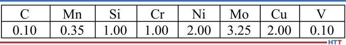
Table 1. Pyrowear 53 base chemistry
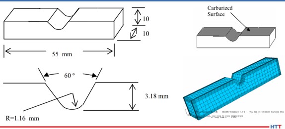
Figure 2. Coupon dimensions, selectively carburized surface, and finite element model
The steel alloy Pyrowear® 53 was chosen as the candidate material for this project. Table 1 shows the base chemistry of Pyrowear 53. The alloy is used extensively in the aerospace industry as a transmission gear material due to its ability to resist softening at high temperature in the hard carburized case, while maintaining high core impact strength and fracture toughness. A specially designed “V” notch 3-point bend fatigue sample was created by the company in conjunction with input from experts at the Army Gear Research Lab at NASA-Glenn and Bell Helicopter. The design was chosen to mimic behavior of a gear tooth root during loading. Figure 2 shows the dimensions of the coupon, the selectively carburized surface, and the finite element model used to explore the effects of process parameter changes on residual stress.
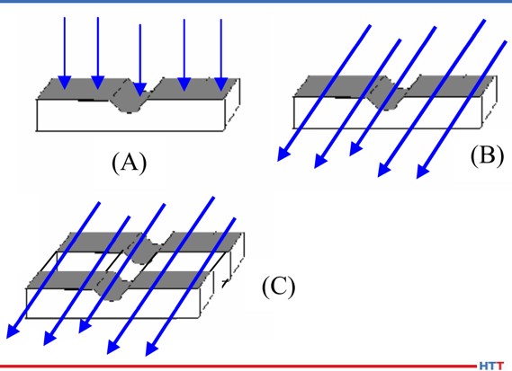
Figure 3. Schematic of intensive quenching orientation for Phase 1 study
A total of 40 coupons were manufactured and selectively carburized. The coupons were then split into two groups. Both groups were subjected to the same 1674°F (912°C) austenitizing, - 110°F (-79°C) cryogenic treatment, and double temper at 450°F (232°C). However, the two groups differ in the method of quenching, with one group quenched using the standard oil quenching practice for Pyrowear 53 and the second group quenched using the Intensive Quenching method. The two groups were processed separately. The Intensive Quenching unit utilized in this project uses a high velocity water stream to quench one component at a time. Figure 3 shows the coupon orientation within the intensive quenching unit. The blue arrow indicates the direction of water flow over the coupon.
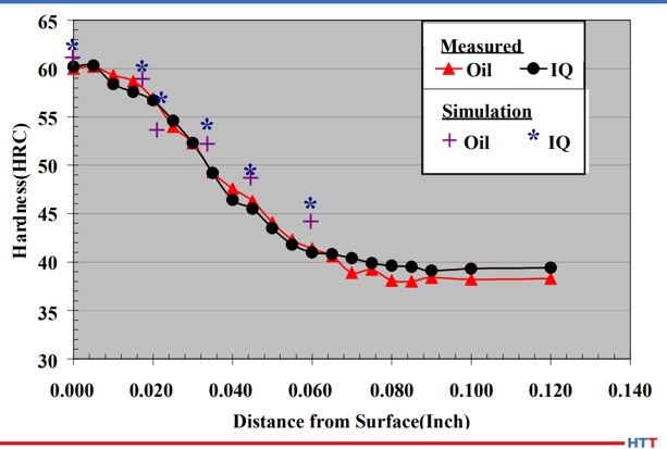
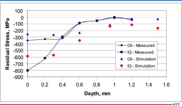
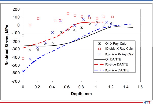
After processing all of the coupons and modeling the two processes using the same heat treatment simulation software, a comparison was made between the two processes and the simulation. Figure 4 shows the hardness profile comparison at the center of the notch. As seen, the hardness profiles are equivalent between the two processes. This is expected as the carbon and other alloy content in the material is identical between the two processes. The simulation also matches the experimental data well. While the hardness profiles are identical between the two processes, the residual stress profiles at the center of the notch are not the same, as shown in Figure 5. The intensively quenched coupon has a surface compressive stress of 800 MPa, more than double the compression induced by oil quenching. However, at 0.4 mm, the profiles converge. This is significant as the surface can now carry a higher load, yet no detrimental effects are seen subsurface. Again, the simulation matches the experimental results well.
Satisfied with the increased surface compressive stress gained through the use of Intensive Quenching, 3-point bend fatigue testing was initiated at Case Western Reserve University. Load control was applied, with a minimum to maximum load ratio of 0.1 used to maintain a state of cyclic tension. This type of loading ensures the sample remains stationary throughout the duration of the test.
Figure 4. Phase 1 hardness profile comparison between oil quench, Intensive Quench, and DANTE simulations of the two processes
Figure 5. Phase 1 residual stress profile at the notch center comparison between oil quench, intensive quench, and DANTE simulations of the two processes
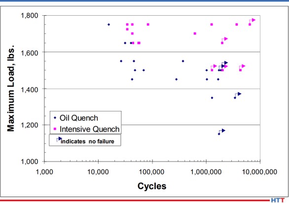
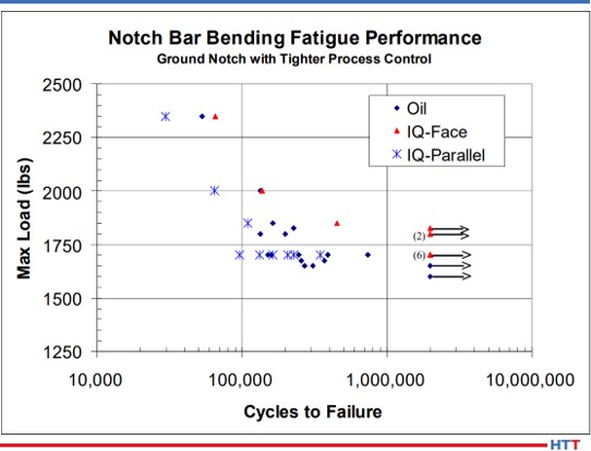
Figure 6 shows the results of the bend fatigue testing. It appears from Figure 6 that the increased residual surface compression of the intensively quenched coupons contributed to an increase in bend fatigue performance when compared to the oil quenched samples. However, some scatter does exist. Several parameters could have influenced these results.
First, during coupon manufacturing, the notch was created in the coupon using a milling operation and then heat treated. After heat treatment, no finishing operation was performed on the notch. Therefore, the possibility of surface defects existed. Any surface defect can create a stress riser, creating a stress condition which exceeds the expected stress given the loading conditions and geometry. However, surface defects would not be consistent coupon to coupon, and therefore have the potential to skew fatigue results.
Figure 6. Phase 1 bending fatigue comparison between oil quench and intensive quench
The second parameter that could have influenced the scatter in the fatigue results is related to the intensive quenching process itself. The process is dependent on a steep temperature gradient to generate the greatest level of compressive stress. This requires high velocity water to impact the component quickly, as any delay or low velocity water impingement can create shallow temperature gradients. Using the DANTE software, it was determined that in order to generate the greatest amount of surface compression, full flow must be achieved in a maximum of one second. This was a significant discovery that may have gone unnoticed if simulation was not used to explore process parameter sensitivities. It was unclear if the equipment operation met this maximum time restraint during processing of all coupons. However, due diligence was given to system operation in future experiments with improved consistency.
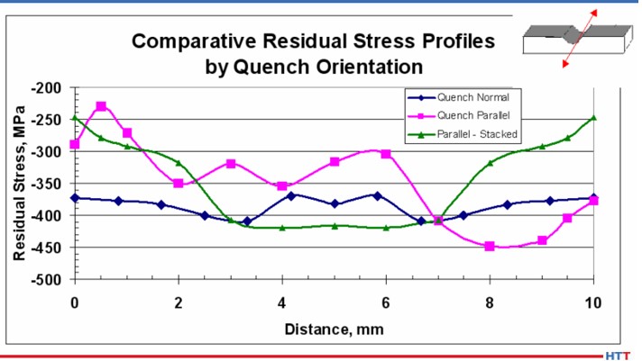
Figure 7. Schematic of intensive quenching orientations for Phase 1A study
Another processing parameter that has the potential to influence residual stress generated during an intensive quenching operation is the orientation of certain geometric features relative to the high velocity water flow. Again, the DANTE software was utilized, in lieu of expensive physical testing, to determine the optimum orientation of the fatigue sample in the intensive quenching unit. Figure 7 shows the three orientations evaluated. The orientation in Figure 7(A) has the water impinging on the notch surface and Figure 7(B) has the water impinging on the side of the coupon, with water flowing parallel to the notch. Recall that the original coupon orientation, shown in Figure 3, has the water impinging on the top of the coupon and flowing perpendicular to the notch. The final configuration, shown in Figure 7(C), places two coupons in the chamber side-by-side. This configuration has the potential to create an even steeper thermal gradient within the coupon due to the two coupons sharing thermal energy from being in contact with one another, and thus having a slower cooling rate in the core than a single coupon.
Figure 8 shows the surface residual stress across the width of the notch center, as shown by the red arrow in the Figure 8 inset, for the three orientations predicted by the simulation. Of the three orientations evaluated, orientation (A) resulted in the greatest magnitude of compression, as well as remaining the most consistent across the width of the notch. The residual stress contour plots of the three orientations, shown in Figure 9, confirm the uniformity of the residual stress profile across the width of the notch for orientation (A). The other two orientations show markedly reduced compressive surface stress near the edges of the notch. This type of profile would most likely fail in fatigue at those locations with reduced surface compression. To achieve the most consistent performance results, the most uniform surface condition should be sought.
Figure 8. DANTE residual stress profile predictions across the width of the notch center, as shown schematically in the figure inset, for the Phase 1A study
Figure 9. DANTE residual stress predictions for the Phase 1A study
The residual stress profiles at the center of the notch are shown in Figure 10 for oil quenched coupons, intensively quenched coupons with orientations (A) (“IQ-face”) and orientation (B) (“IQ-side”), and the company simulation results for the three processes. As predicted by simulation, and confirmed by X-ray diffraction measurements, the intensively quenched coupon in orientation (A) results in the highest magnitude of residual surface compressive stress, as well as having the deepest compression. The measurements also revealed that intensively quenching the coupon geometry in orientation (B) results in a slight increase in surface compression, when compared to oil quenching, but the compression is reduced much quicker in the orientation (B) coupon. Based on the simulation results, it was surmised that orientation (A) would outperform orientation (B) in bend fatigue, and oil quench would outperform orientation (B). Due to the poor residual stress distribution predicted for orientation (C), no coupons were processed in this orientation.
Figure 10. Residual stress profile measurements and predictions at the notch center for orientations A and B of the Phase 1A study
Figure 11 shows the bend fatigue results for the oil quenched coupons and the intensively quenched coupons in orientation (A) (“IQ-Face”) and orientation (B) (“IQ-Parallel”). As predicted from information gleaned from the DANTE simulation, orientation (A) outperformed the oil quenched coupons. The orientation (A) coupon recorded an endurance limit of approximately 1800 MPa, while the oil quenched coupons recorded an endurance limit of approximately 1600 MPa. This difference is approximately equal to the difference in near surface compressive stress induced by the two processes. The orientation (B) coupons failed to successfully complete a test at the loads chosen. Convinced that increasing the magnitude of surface compression through a process change could improve fatigue performance in transmission gears, Phase Two was initiated to evaluate the process change on an actual gear component.
Figure 11. Phase 1A bending fatigue comparison between oil quench and Intensive Quench
Conclusion
In conclusion, a project was launched to use heat treatment modeling, in conjunction with physical testing, to determine the effects of a process change designed to induce a greater magnitude of compressive surface stress to improve bend fatigue performance of a low-alloy gear steel. Pyrowear 53 was chosen as the gear steel and Intensive Quenching was chosen as the process change to induce a greater magnitude of residual surface compressive stress. Before any testing was initiated, DANTE modeling was used to show that intensive quenching could indeed produce a greater magnitude of surface compression, possibly improving bend fatigue performance by introducing a compressive mean stress and lowering the actual stress witnessed by the component. This modeling was also used to determine the maximum amount of time which may be used by the intensive quenching equipment to reach a full flow condition and still produce an increase in residual surface compression, as well as evaluate the residual stress profile of several different intensive quenching orientations.
Using this modeling to direct physical testing, hardness, residual stress, and bend fatigue performance were evaluated in coupons quenched in oil and coupons intensively quenched in three different orientations. The fourth orientation was not tested as modeling showed the residual stress profile to be unfavorable. Physical testing confirmed the modeling results: hardness profiles are equivalent between the processes, and residual stress profiles coincide with modeling results. Bend fatigue performance was indeed increased by increasing the magnitude of surface compressive stress. Phase One of the project showed that bend fatigue performance was improved by increasing the magnitude of the part’s surface compressive stress and demonstrated that modeling can be an invaluable tool when evaluating process parameter changes on material performance.
References
1. N. I. Kobasko and V. S. Morganyuk, “Numerical Study of Phase Changes, Current and Residual Stresses in Quenching Parts of Complex Configuration,” Proceedings of the 4th International Congress on Heat Treatment of Materials, Berlin, Germany, 1 (1985), 465-486.
2. N. I. Kobasko, “Intensive Steel Quenching Methods. Theory and Technology of Quenching”, SpringerVerlag, New York, N.Y., 1992, 367-389.
3. N. I. Kobasko, “Method of Overcoming Self Deformation and Cracking During Quenching of Metal Parts,” Metallovedenie and Termicheskay Obrabotka Metallov (in Russian), 4 (1975), 12-16.
4. M. Hernandez et al., Residual Stress Measurements in Forced Convective Quenched Steel Bars by Means of Neutron Diffraction”, Proceedings of the 2nd International Conference on Quenching and the Control of Distortion, ASM, (1996), 203-214.
5. M. A. Aronov, N. I. Kobasko, J. A. Powell, J. F. Wallace, and D. Schwam, “Practical Application of the Intensive Quenching Technology for Steel Parts,” Industrial Heating Magazine, April 1999, 59-63.
6. A. M. Freborg, B. L. Ferguson, M. A. Aronov, N. I. Kobasko, and J. A. Powell, Intensive Quenching Theory and Application for Imparting High Residual Surface Compressive Stresses in Pressure Vessel Components,” Journal of Pressure Vessel Technology, 125 (2003), 188-194.
7. B. L. Ferguson, A. M. Freborg, and G. J. Petrus, “Comparison of Quenching Processes for Hardening a Coil Spring,” Advances in Surface Engineering, Metallurgy, Finishing and Wear, SAE (01) 1373, (2002).
About the Author: Justin Sims has been with DANTE Solutions for eight years and is an excellent analyst and expert modeler of steel heat treat processes using the DANTE software. His project work includes development, execution, and analysis of carburization, nitriding, and quench hardening simulations. He has developed the DANTE HELP packages and is the primary trainer and software support person for the DANTE software.


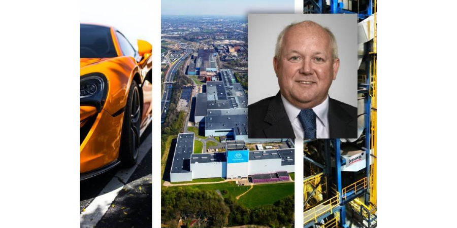
 European manufacturer thyssenkrupp Steel Europe AG (tkSE) is revamping burner technology at their continuous galvanizing line located in Bochum, Germany. This modernization measure is an important cornerstone in enabling thyssenkrupp Steel to produce high-strength steels (AHSS) in Bochum in the highest quality and with increased production capacity for further use in the automotive industry.