A notable provider of vacuum melting systems recently supplied two vacuum induction melting systems to the power and gas division of a power company.
Retech Systems LLC, a subsidiary of SECO/WARWICK Group, provided two vacuum induction melting (VIM) systems for Siemens Power and Gas division.
Retech’s technologies have been applied to melting, refining, casting and atomizing reactive and refractory metals, such as Titanium and its alloys, super alloys, and rare earth metals. Retech VIM furnace systems are used for applications including automotive, consumer, aerospace, and energy utilizing equiax, directionally solidified, or single-crystal investment castings.
Retech Vacuum Induction DS Furnace
One vacuum induction melting directional solidification/single crystal/equiax pitless (VIM DS/SC/EQ) combo casting furnace and one vacuum induction melting directional solidification/single crystal (DS/SC) solidification casting furnace system were installed in Siemens’ new plant. In addition to the two VIM furnace systems already supplied, two more pitless DS/SC VIMs will be supplied later this year.
Retech designs pitless DS/SC Furnaces in hopes of reducing or eliminating costs, time, disruptions to facility production, and confined space entry to pits required with the installation of the new pitless VIM furnaces at the facility.
Earl Good, VP – Global Vacuum Melting, Managing Director Retech Systems LLC
“The melting systems that Retech is delivering to Siemens, incorporate industry leading special design features such as: a reliable and maintenance friendly design ideal for faster and more flexible operation, superb process control for repeatability and high yields, as well as Retech’s new pitless mold elevator that can be utilized on Directional Solidification/Single Crystal furnaces,” said Earl Good, VP – Global Vacuum Melting, Managing Director Retech Systems LLC.
A Dozen Quick Heat TreatNews Items to Keep You Current
Heat TreatToday offers News Chatter, a feature highlighting representative moves, transactions, and kudos from around the industry.
Personnel and Company Chatter
Joyce Paliganoff (Midwest RSE), Patrick Heiser (Southeast RSE), and Larry Gomez (West/Northwest RSE) were recently hired by Ipsen USA as part of an initiative to double the number of Regional Sales Engineers (RSEs) by year-end.
A $9M investment provides needed space for capacity increases for Mercury Marine, which recently opened its 23,500 square foot expansion to its diecasting facility, where the company will manufacture complex blocks, driveshafts, and gearcases for Mercury outboards. In addition, Mercury will add another 4,500-ton die-cast machine giving the company two of the largest of its kind in North America.
SPIROL employees, company executives, board members, state representatives, and other honored guests gathered to celebrate the completion of the major expansion to SPIROL’s world headquarters and largest global manufacturing facility located in Northeastern Connecticut.
Digital manufacturing company, Protolabs has launched production capabilities for its metal 3D printing service. The new capabilities use secondary processes to improve the strength, dimensional accuracy, and cosmetic appearance of metal parts.
Equipment Chatter
A manufacturer in the automotive industry recently purchased an electrically heated enhanced duty walk-in series oven from Wisconsin Oven Corporation. The batch oven will be used for pre-heating racks of plastic parts prior to painting.
A leading supplier of high-quality automotive parts commissioned a Brinell hardness testing specialist for a second bespoke system for the intricate inspection of automotive suspension components. The challenge that Foundrax faced was that the hardness test location as specified by the car manufacturer was in an extremely tight space, hemmed in on three sides by vertical sections and almost no test area to work with. As many of these parts are hollow, there is no other position which would be strong enough to allow for a reliable test.
A retort box furnace was shipped and installed at the facility of an aerospace components manufacturer based in the southern U.S by L&L Special Furnace Co., Inc. The furnace is used to de-binder ceramic matrix composite components deployed in the aircraft industry. The main function of the furnace is to remove all organics and other materials used in the product prior to placing it in a high-fire vacuum chamber. This de-bindering process is extremely important and allows for a finished product that is not only very strong but also lightweight.
No. 824 is a 500°F (260°C), modified universal oven from Grieve, currently used for housing a vertical conveyor system at the customer’s facility. Grieve also shipped No. 797, a 260°F (127°C), clean room cabinet oven, to be used for drying coating on printed circuit boards at the customer’s facility.
Qinghai Zhuofeng New Material Co., Ltd, based in China, recently received shipment of two continuous annealing and processing lines, each with an annual capacity of 110,000 tons, from technology Group ANDRITZ.
Kudos Chatter
In 1986, Dave Strand was hired by Wisconsin Oven Corporation as a shop worker. In 2019, he retires as President & CEO of Thermal Product Solutions, LLC, the parent company of Wisconsin Oven. Dave Strand has dedicated 33 years to the continued growth of Wisconsin Oven Corporation.
Dave Strand
During the HEAT TREAT 2019 conference, Fluxtrol Inc., in conjunction with the ASM Heat Treating Society, will be recognizing and awarding academic researchers and young scientists in the field of thermal processing. Two Fluxtrol/ASM awards will be given, the “Prof. Valentin S. Nemkov Academic Research Award,” and the “Fluxtrol Student Research Award”.
In an effort to continually improve the workplace environment for all Employee-Owners, the Pelican Wire leadership team recently announced a new, comprehensive “Paid Family Leave” benefit. This expanded paid-leave benefit includes maternity/paternity leave and leave for primary caregivers of immediate family members with a serious health condition requiring
full-time care.
Heat TreatToday is pleased to join in the announcements of growth and achievement throughout the industry by highlighting them here on our News Chatter page. Please send any information you feel may be of interest to manufacturers with in-house heat treat departments especially in the aerospace, automotive, medical, and energy sectors to the editor at editor@heattreattoday.com
A large Ohio manufacturer of bearings and power transmissions recently purchased an established roller chain company to enhance their distribution and manufacturing services.
The Timken Company, producer of engineered bearings and power transmissions, acquired The Diamond Chain Company from Amsted Industries. Based in Indianapolis, Indiana, Diamond Chain supplies high-performance roller chains for industrial markets for a range of sectors, including industrial distribution, material handling, food and beverage, agriculture, and construction.
The Diamond Chain Company
When heat treating their components, Diamond Chain uses dedicated carburizing furnaces set to precise temperatures. To produce maximum carbon penetration for a high carbon surface and low carbon core, the company strives to closely control atmosphere and quench. This process is designed to achieve consistent depth of case hardening increasing strength, durability, and wear resistance.
Richard G. Kyle, Timken President and Chief Executive Officer
“The acquisition of The Diamond Chain Company adds another strong industrial brand with a reputation for quality, reliability and performance to Timken’s growing power transmission portfolio,” said Richard G. Kyle, president and chief executive officer at Timken. “Diamond Chain is a premier brand in the North American distribution channel and is an excellent strategic fit with our Drives chain business. The acquisition expands our leadership in roller chain, builds on our strong position in distribution and adds depth to our manufacturing capabilities in Asia. We expect to drive significant synergies with the combination of Diamond Chain and Drives.”
A steel manufacturer recently opened an addition to its Mesa, Arizona, facility featuring the necessary space and equipment to add spooled rebar to their line of products.
The ribbon-cutting ceremony for CMC Steel Arizona’s Expansion. (City of Mesa)
Commercial Metals Co. announced the opening of their 63,000-square-foot expansion and manufacturing line to produce spooled rebar at CMC Steel Arizona, a micro mill in southeast Mesa.
The company’s commitment to produce hot-rolled, spooled rebar at the Mesa mill makes it CMC’s second U.S. spooler operation. The first opened last year in Durant, Oklahoma.
CMC Steel Arizona also manufactures concrete reinforcing bar, or rebar, and steel t-posts, which are primarily produced from recycled scrap metal.
“CMC commitment to innovation and new technology makes them a leader in the steel production, fabrication and recycling industry.” – John Giles, Mayor of Mesa
Dan Szynal, VP of Engineering & Technical Services, Plibrico
Aluminum processors face constant challenges to their aluminum melt operations. Due to robust demand, processors often operate these furnaces at higher temperatures to maximize production rates. As a result, one of the costliest operational challenges is the aggressive formation of corundum deposits in their furnaces.
In this article, Dan Szynal, VP of Engineering & Technical Services, Plibrico, discusses the causes and concerns of corundum growth and outlines excessive, damaging, and costly corundum growth can be mitigated with the right refractory materials, coupled with the correct maintenance and watchful operation.
Root Causes of Corundum Growth
Corundum growth in a refractory lining of an aluminum furnace occurs due to a reaction between the alumina-silicate refractory and molten aluminum. Corundum formation can occur both externally and internally in the refractory lining.
There are four identifiable root causes that promote corundum growth:
High temperature
Presence of oxygen
Alloy composition
Use of fluxes and fluoride salts
Corundum Formation Illustration
High temperatures accelerate the reduction of oxides in the refractory. The higher the temperatures, the more quickly non-wetting agents lose their effectiveness. Aluminum begins to penetrate the refractory matrix because of decreases in aluminum viscosity and surface tension. Excessive furnace temperature can be the result of several causes: overfiring, improper furnace control, or inaccurate thermocouple placement. For example, a thermocouple that is recessed into the refractory lining by 2 inches may underreport temperatures by several hundred degrees.
Oxygen drives the reaction process in two ways: as an atmospheric gas, and as a reducible oxide in the refractory. Minimizing oxygen by controlling negative pressure sources such as doors, windows, and well openings reduces the potential for reaction. Proper flue sizing and burner stoichiometry also reduce excess oxygen and improve furnace energy efficiency.
Alloy composition can be a factor. Some aluminum alloys contain elements that reduce the silica as well as iron oxide, zinc oxide, and other oxides in refractories. Careful attention is necessary when choosing an appropriate refractory for more aggressive aluminum alloys to reduce the potential for reaction.
The use of fluxes and fluoride salts like cryolite Na3AlF6 in aluminum melting accelerate the reduction of oxides in the refractory. Their alkaline properties also reduce the local melt temperature of the refractory at the bellyband and then infiltrate the furnace lining. Over time, with a lack of regular maintenance, the corundum buildup will reduce furnace performance and increase aluminum loss.
Trouble Spots
The spread of corundum growth occurs most commonly in areas where its formation mechanisms of heat and oxygen are present. Typical problem areas include doors, openings, flue areas, and burner cones due to the potential for excess oxygen. Negative furnace pressure can also lead to leakage from the outside. Other common areas of formation include rear walls and bellyband areas where regular cleaning and maintenance are more difficult.
Control and Avoidance
The key to fighting corundum starts with choosing the proper refractory material for molten aluminum contact. The development of effective refractory additives that combat corundum, including non-wetting additives, dense oxide barrier formers, and pore-size reducers was pioneered by Plibrico, which includes these additives in products aimed at:
increasing wetting resistance and reducing the potential for oxidation-reduction of the refractory (The Plicast Al-Tuff® system)
forming a reactive layer to resist molten aluminum penetration up to 2000°F (Plibrico’s Al-Shield™ refractories)
offering good resistance to metal slag penetration, especially in higher temperatures, and adhering well to the existing refractory for repairs (Phos-bonded castables like Plibrico’s Exo-set Uno™)
In general, PliPartner refractory contractors tell us that they find phos-bonded plastic refractories to be excellent repair materials for aluminum processors. They are usually low in free silica and nonwetting. The material bonds chemically to existing refractory, making them easier to install, and phos-bonded plastic refractories are an excellent solution for corundum growth at the bellyband.
Best Practices That Will Help
A regular maintenance plan can go a long way to increasing refractory life; a schedule is essential. A knowledgeable refractory expert with genuine experience in aluminum heat processes can help with ideal schedules and checklists.
Corundum buildup is a common concern among aluminum furnace end users. Optimally, the longevity of a furnace lining depends on best practices in refractory materials and installation methods, knowing the past refractory performance history to evaluate future performance, managing expectations of furnace production output, and monitoring regular maintenance and operation of the furnace.
These factors are measurable key performance indicators that will help decision makers design and build good refractory linings for the demanding needs of aluminum producers today. Considering these factors and balancing them according to the producers’ needs can deliver a higher-quality product for longer life.
A large aluminum producer recently announced a large investment in a new rolling plant in Ashland, Kentucky.
Braidy Industries, Inc. (Braidy) and Rusal jointly announced the approval by their respective Boards of Directors for Rusal to invest $200 million in Braidy Atlas mill. The companies estimate that it has been more than three decades since a greenfield aluminum rolling mill like Braidy was built in the U.S. The deal is expected to close in the second quarter of 2019.
Craig Bouchard, Braidy Industries Chairman and CEO
“This is a sustainability match made in heaven for the global aluminum industry,” said Craig Bouchard, Braidy Industries Chairman and CEO.
Rusal intends to supply 200,000 tons of certified low-carbon prime aluminum ingot and slabs each year for a 10-year period, allowing Braidy to target lower carbon emissions.
Braidy is dependent on long-term supplies of high-quality, low-carbon aluminum, which is rarely supplied in the high quantity required for their production. If met, this order would be one of the world’s largest for one mill of high-quality, pre-alloyed and low-carbon primary aluminum slabs.
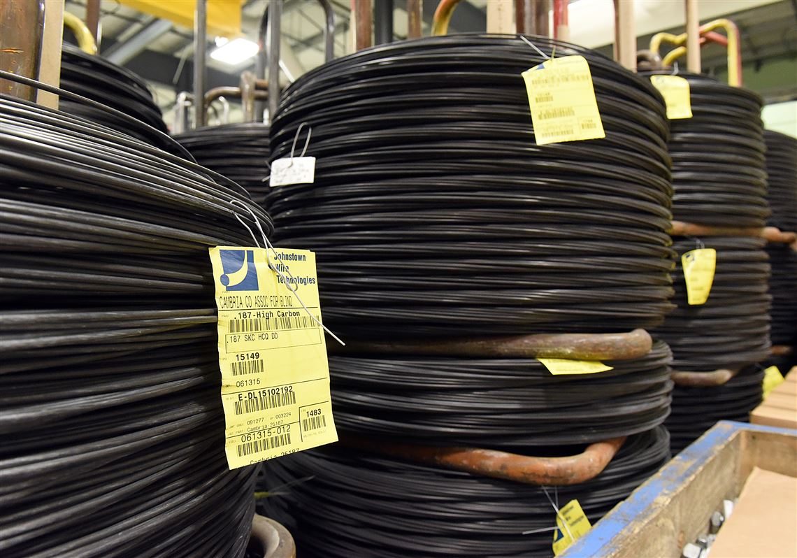
A British steel company recently acquired a large Pennsylvania producer of value-added carbon and alloy wire.
Liberty Steel, part of the global GFG Alliance, purchased Johnstown Wire Technologies (JWT) in Johnstown, Pennsylvania, a large producer of value-added carbon and alloy wire in North America.
The acquisition allows Liberty the opportunity to manufacture a range of high-value carbon and alloy wire products for multiple end markets including the infrastructure, automotive, utility, and consumer sectors.
The advanced manufacturing facility at Johnstown will complement Liberty’s melting and rolling operations at Georgetown, South Carolina, and Peoria, Illinois, and, combined with its scrap processing plant in Tampa, Florida, will have a wide presence in the U.S. steel market.
The 638,000-square-foot Johnstown site has been a high-profile steel manufacturing facility for over 100 years and is one of the few U.S. producers of CHQ, electro-galvanized, aluminized and spring wire. JWT currently holds a high market position in the electro-galvanized and aluminized sectors.
Source: Pittsburgh Post Gazette
With more than half of JWT’s output sold into the transportation market, Liberty is also aiming to capitalize on continued growth in U.S. vehicle production. It is one of the largest producers in the U.S. of CHQ wire, which is used in automotive products such as engine block bolts and brake pad rivets.
Liberty hopes that the acquisition will increase its capability to meet the “Made in America” specifications required for public infrastructure and utility contracts.
Grant Quasha, Chief Investment Officer for GFG in North America
“This is another very significant step towards our ambitious U.S. goals,” said Grant Quasha, Chief Investment Officer for GFG in North America. “JWT is a profitable business with a skilled workforce and tremendous pedigree in the industry, so we look forward to welcoming it into the GFG USA family and helping it build an even stronger future.”
“We are excited to be joining the GFG family of global businesses and see this as a tremendous opportunity to further our position as a leading manufacturer of steel wire in North America,” said Jack Miller, President and CEO of Johnstown Wire Technologies.
Sanjeev Gupta, GFG Group executive chairman
“It’s a great pleasure to welcome 250 highly-skilled new members to our family,” said Sanjeev Gupta, GFG Group executive chairman. “Integration upstream and downstream with value-added product manufacturing is an absolute core to our U.S. steel strategy. The addition of high-quality specialized facilities at Johnstown further strengthens our existing facilities at Georgetown and Peoria.”
Liberty entered the U.S. market in 2017 by acquiring ArcelorMittal’s Georgetown mill and followed up with the purchase of Keystone Consolidated Industries, including its flagship Peoria mill, in 2018.
A North American steel manufacturer recently made an investment with intent to expand its services at its South Carolina bar mill.
Nucor Corporation announced plans to add vacuum degassing to its engineered bar services at its bar mill in Darlington, South Carolina. Nucor hopes that by providing this service the mill will be better equipped to produce engineered bar products according to high-quality specifications in the industry. The vacuum degassing system is expected to begin operating in late 2020.
John Ferriola, Chairman, CEO, and President of Nucor Corporation
“This strategic investment complements our existing bar mills that primarily produce engineered bar products in Norfolk, Nebraska, Memphis, Tennessee, and Wallingford, Connecticut. It will position us to better serve our customers in the Southeastern United States and support the growing demand in the region for higher quality automotive and other specialty steel applications,” said John Ferriola, Chairman, CEO, and President of Nucor.
Nucor Steel South Carolina, the first steel mill Nucor built, now employs more than 450 teammates and will recognize its 50th anniversary this summer at the Darlington facility.
Producing steel by means of melting recycled scrap in an electric arc furnace (“EAF”), the mill influenced the way steel is now made in the United States. Today, Nucor estimates that approximately 70 percent of the steel made in this country is produced using EAFs.
In the modern automotive manufacturing industry, CQI-9 HTSA (AIAG) has become a key part of driving process and product quality in heat treatment applications. The standard has a broad scope and covers many different aspects of common heat treatment processes (see Process Tables A-H in the standard) and monitoring requirements used. A critical part of the standard is the requirement to perform a temperature uniformity surveys (TUS) in order to validate the temperature uniformity of the qualified work zones and operating temperature ranges of furnaces or ovens used. In this Heat TreatProduct Spotlight, Dr. Steve Offley, a.k.a. “Dr. O”, Product Marketing Manager with PhoenixTM, discusses the challenges of performing a TUS on continuous furnace types and one possible solution his company offers.
CQI-9 Heat Treat System Assessment
A critical part of the CQI-9 HTSA (AIAG) standard is the requirement to perform temperature uniformity surveys (TUSs). The TUS is performed to validate the temperature uniformity characteristics of the qualified work zones and operating temperature ranges of furnaces or ovens used. (See Figure 1.)
Fig 1: Schematic showing TUS principle. Thermocouple measurement from the field test instrument, of the furnace’s actual operational temperature, against a setpoint to check that it is within tolerance. Setpoints and tolerances are defined in CQI-9 Process Tables A-H to match each heat treat process.
The “Thru-Process” TUS Principle
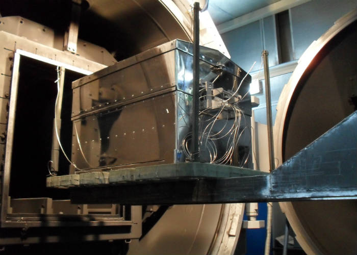
Traditionally, TUSs are performed by using a field test instrument (chart recorder or static data logger) external to the furnace with thermocouples trailing into the furnace heating chamber. This technique has many limitations, especially when the product transfer is continuous such as in a pusher or conveyor-type furnace. The trailing thermocouple method is often labor-intensive, potentially unsafe, and can create compromises to the TUS data being collected (e.g., number of measurement points possible, thermocouple damage, and physical snagging of the thermocouple in the furnace).
Fig 2: PhoenixTM thermal barrier being loaded into a batch furnace with a survey frame as part of the TUS process.
The “Thru-Process” TUS principle overcomes the problems of trailing thermocouples as the multi-channel data logger (field test instrument) travels into and through the heat treat process protected by a thermal barrier (Figure 2). The short thermocouples are fixed to the TUS frame. Temperature data is then transmitted live to a monitoring PC running TUS analysis software, via a 2-way RF telemetry link.
Data Logger Options
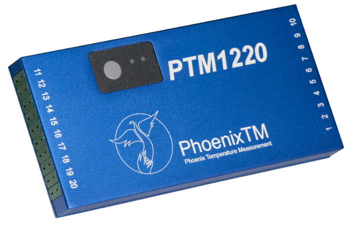
To comply with CQI-9, field test equipment needs to be calibrated every 12 months minimum, against a primary or secondary standard. The data logger accuracy needs to be a minimum +/-0.6 °C (+/-1.0 °F) or +/-0.1% (TABLE 3.2.1).
Fig 3: PhoenixTM PTM1220 20 Channel IP67 data logger comes calibrated to UKAS ISO/IEC17025 as an option with an onboard calibration data file allowing direct data logger correction factors to be applied automatically to TUS data.
The data logger shown in Figure 3 has been designed specifically to meet the CQI-9 TUS requirements offering a +/- (0.5°F (0.3°C) accuracy (K & N). Models ranging from 6 to 20 channels can be provided with a variety of noble and base metal thermocouple options (types K, N, R, S, B) to suit measurement temperature and accuracy demands (AMS2750E and CQI-9).
Mixed thermocouple inputs can be provided to support the process specific requirements and also allow the use of the data logger to perform system accuracy testing (SAT) to complement the TUS.
Innovative Thermal Barrier Design
Fig 4: “Octagonal” thermal barrier fitted to product/survey tray.
CQI-9 covers a wide range of thermal heat treatment processes and as such the thermal protection for the data logger will vary significantly. A comprehensive range of thermal barrier solutions can be provided to meet specific process temperature requirements and space limitations. Figure 4 shows a unique octagonal thermal barrier designed to fit within the boundaries of the product tray/survey frame used to perform a TUS using the “plane method” (See “Thermocouple Measurement Positions (TUS)” below in this article.). The design ensures maximum thermal performance within the confines of a restricted product tray/basket.
Live Radio TUS Communication
Fig 5: Schematic of LwMesh 2-way RF Telemetry communication link from data logger TUS measurement back to an external computer.
The data logger is available with a unique 2-way wireless RF system option allowing live monitoring of temperatures as the system travels through the furnace. Analysis of process data at each TUS level can be done live allowing full efficient control of the TUS process. Furthermore, if necessary, by using the RF system, it is possible to communicate with the logger installed in the barrier to reset/download at any point pre-, during, and post-TUS. In many processes, there will be locations where it is physically impossible to transmit a strong RF signal. With conventional systems, this results in process data gaps. For the system shown in Figure 2, this is prevented using a unique fully automatic “catch up” feature.
Any data that is missed will be sent when the RF signal is re-established, guaranteeing 100% data transfer.
Thermocouple Options (TUS)
In accordance with the CQI-9 standard (Tables 3.1.3 / 3.1.5), thermocouples supplied with the data logger, whether expendable or nonexpendable, meet the specification requirements of accuracy +/-2.0°F (+/-1.1°C) or 0.4%. Calibration certificates can be offered to allow the creation of thermocouple correction factor files to be generated and automatically applied to the TUS data within the PhoenixTM Thermal View Survey Software. Care must be taken by the operator to ensure that usage of thermocouples complies with the recommended TUS life expectancies and repeat calibration frequencies. Before first use, thermocouples must be calibrated with a working temperature range interval not greater than 250°F (150°C). Replacement or recalibration of noble metal (B, R or S) thermocouples is required every 2 years. For non-expendable base metal (K, N, J, E), thermocouples replacement should be after 180 uses <1796°F (980°C) or 90 uses >1796°F (980°C). For expendable base metal (K, N, J, E), thermocouples replacement should be after 15 uses <1796°F (980°C) or 1 use >1796°F (980°C). Note that base metal thermocouples should not be recalibrated.
Thermocouple Measurement Positions (TUS)
To perform the TUS survey, a TUS frame needs to be constructed to locate the thermocouples over the standard work zone to match the form of the furnace. The TUS may be performed in either an empty furnace in which case thermocouples should be securely fixed as shown in Figure 6. A heat sink (thermal mass fixed to thermocouple tip) can be used to create a thermal load to match the normal product heating characteristics. Alternatively, the thermocouples should be buried in the load/filled product basket. See Figure 6 to see schematics of TUS Frames for a box and cylindrical batch furnace with CQI-9-quoted number of thermocouples required to match void volume (Volumetric Method Table 3.4.1).
Fig 6: TUS Thermocouple Test Rigs. Required number of thermocouples: 1) Work Volume < 0.1 m³ (3 ft³) = 5; 2) Work Volume 0.1 to 8.5 m³ (3 to 300 ft³) = 9; 3) Work Volume > 8.5 m³ one thermocouple for every 3 m³ (105 ft³). (Click on the images for larger display.)
Fig. 7.1, 7.2. PhoenixTM system showing 9 Point TUS survey rig and Thermal View Software TUS frame library file showing as part of TUS report exactly where thermocouples are positioned. (Click on the images for larger display.)
For continuous conveyorized furnaces, it is recommended that an alternative thermocouple test rig is employed called the “plane method”. Since the system travels through the furnace it is only necessary to monitor the temperature uniformity over a 2-dimensional plane/slice of the furnace (Figure 8). The required number and location of thermocouples are shown in Table 1 (CQI-9 Table 3.4.2).
(Click on the images for larger display.)
Table 1: Required thermocouples and locations for differing work zones (Plane Method)
(1) 2 Thermocouples within 50 mm work zone corners 1 Thermocouple center. (2) 4 Thermocouples within 50 mm work zone corners. Rest symmetrically distributed.
“Thru-Process” Temperature Uniformity Survey (TUS) Data Analysis and Reporting
Operating the PhoenixTM System with RF Telemetry, TUS data is transferred from the furnace directly back to the monitoring PC where, at each survey level, temperature stabilization and temperature overshoot can be monitored live, with thermocouple and logger correction factors applied. The Thermal View Survey software generates TUS reports which comply with the requirements of AMS2750E/CQI-9 standards.
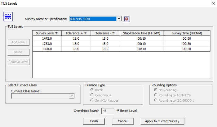
As defined in CQI-9 (Section 3.4) for furnace with an operating temperature range ≤ 305°F (170°C), one setpoint temperature (TUS level) within the operating temperature range is required. If the operating temperature of the qualified work zone is greater than 305°F (170°C), then the minimum and maximum temperatures of the operating temperatures range shall be tested.
The TUS levels can be automatically set up in the TUS analysis software. Figure 9 shows both the TUS level file and TUS levels applied against the TUS survey trace.
Fig. 9.1Fig. 9.2
Fig 9.1, 9.2 PhoenixTM Thermal View Survey Software showing TUS Level set-up and application to TUS trace.
Within CQI-9, there is a very prescriptive list of what should be contained in the TUS report (Section 3.4.9).
To comply with all said requirements, the software package provides a comprehensive reporting package as shown below.
Fig 10.1, 10.2, 10.3. TUS Report showing a TUS profile at three set survey temperatures (graphical and numerical data). The probe map shows exactly where each thermocouple is located and easy trace identification. A detailed TUS report is generated, meeting full CQI-9 reporting requirements. (Click on the images for larger display.)
Overview
The PhoenixTM Thru-Process TUS System provides a versatile solution for performing product temperature profiling and furnace surveying in industrial heat treatment meeting all TUS requirements of CQI-9 within the automotive manufacturing industry, providing the means to understand, control, optimize and certify the heat treat process.
The parent company of a U.S.-based induction heating equipment manufacturer was selected to supply an induction heating system to an international fan manufacturer, replacing their aging heating system with a UNI HEAT system.
Elektror, headquartered in Ostfildern, Germany, purchased the induction heating system from EMAG eldec, the parent company of eldec LLC, a heating equipment supplier in Auburn Hills, Michigan. Elektror has two production sites in Waghäusel, Germany, and Chorzów, Poland, and creates industrial fans and side channel compressors. The Waghäusel site, which manufactures nearly 250 devices a day, purchased the UNI HEAT from EMAG eldec in hopes of achieving precise induction heating of motors for their fans.
Induction heating is used to manufacture the electric motors that drive Elektror’s fans and side channel compressors by combining the empty stator housing and the motor winding. To achieve this, the housing is first heated to a temperature of 280 to 300 degrees Celsius. This causes it to expand and allows for the motor winding to be inserted. Once they have cooled down, both components establish a form-fitting and solid bond. Although Elektror used the joining process previously, their former induction heating system was in need of improvement. For instance, it did not indicate the component’s actual temperature after heating, which led to extended throughput times when joining the empty stator housing and the motor winding. The company hoped to improve this process and make it more reliable.
Roland Sand, head of the production team at Elektror, found Emag Eldec with an Internet search for potential suppliers that would have the required expertise and proximity to Waghäusel to deliver timely service. His company then visited the EMAG eldec site in Dornstetten and discussed the project. “In the end,” he said, “it was EMAG eldec’s extensive experience with induction turn-key solutions that convinced us.”
Roland Sand (2nd from left) with colleagues at Elektror and a representative from EMAG eldec (Source: EMAG eldec).
The two companies collaborated on subsequent development of the UNI HEAT system. They worked out details regarding the control unit, safety, and the design of the new comprehensive solution, including a modified induction heating process. To ensure precise heating results, they set an induction rod to plunge into the hollow component rather than using a ring inductor, which enclosed the component from outside.
They implemented several steps to develop process reliability. First, the operator places the empty housing in the custom-fit workpiece carrier and pushes it inside the UNI HEAT. As soon as he closes the front door, the first mechanical processes are initiated in the machine; the component is lifted and encompasses the inductor when it reaches its processing position. The actual induction heating then only lasts 30 to 120 seconds depending on the size of the housing. When complete, a warning light signals to the operator that the component can be removed. The actual component temperature is continuously shown on the operator panel.
The operator then places the hot housing on a mold, which is ready at the cooling location. He pushes the motor winding from the top into the housing. The component is cool in approximately two minutes and then placed on a conveyor belt.
The machine undergoes many retooling processes, because Elektror produces a variety of motor sizes, and sometimes the batches change several times a day. The process is brief; the operator loosens two screws on the inductor mount, removes the inductor and attaches one of six different inductors for the various empty housings. The workpiece carrier is simply set down and can be changed easily in a few seconds. The program on the operator panel can be set in just a few clicks, which completes the process.