Sponsored content
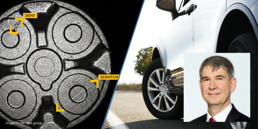
In the modern automotive manufacturing industry, CQI-9 HTSA (AIAG) has become a key part of driving process and product quality in heat treatment applications. The standard has a broad scope and covers many different aspects of common heat treatment processes (see Process Tables A-H in the standard) and monitoring requirements used. A critical part of the standard is the requirement to perform a temperature uniformity surveys (TUS) in order to validate the temperature uniformity of the qualified work zones and operating temperature ranges of furnaces or ovens used. In this Heat Treat Product Spotlight, Dr. Steve Offley, a.k.a. “Dr. O”, Product Marketing Manager with PhoenixTM, discusses the challenges of performing a TUS on continuous furnace types and one possible solution his company offers.
CQI-9 Heat Treat System Assessment
A critical part of the CQI-9 HTSA (AIAG) standard is the requirement to perform temperature uniformity surveys (TUSs). The TUS is performed to validate the temperature uniformity characteristics of the qualified work zones and operating temperature ranges of furnaces or ovens used. (See Figure 1.)

The “Thru-Process” TUS Principle
Traditionally, TUSs are performed by using a field test instrument (chart recorder or static data logger) external to the furnace with thermocouples trailing into the furnace heating chamber. This technique has many limitations, especially when the product transfer is continuous such as in a pusher or conveyor-type furnace. The trailing thermocouple method is often labor-intensive, potentially unsafe, and can create compromises to the TUS data being collected (e.g., number of measurement points possible, thermocouple damage, and physical snagging of the thermocouple in the furnace).
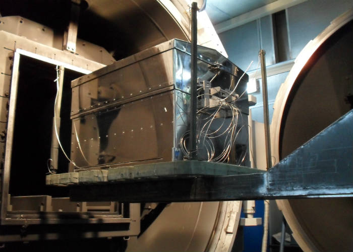
The “Thru-Process” TUS principle overcomes the problems of trailing thermocouples as the multi-channel data logger (field test instrument) travels into and through the heat treat process protected by a thermal barrier (Figure 2). The short thermocouples are fixed to the TUS frame. Temperature data is then transmitted live to a monitoring PC running TUS analysis software, via a 2-way RF telemetry link.
Data Logger Options
To comply with CQI-9, field test equipment needs to be calibrated every 12 months minimum, against a primary or secondary standard. The data logger accuracy needs to be a minimum +/-0.6 °C (+/-1.0 °F) or +/-0.1% (TABLE 3.2.1).
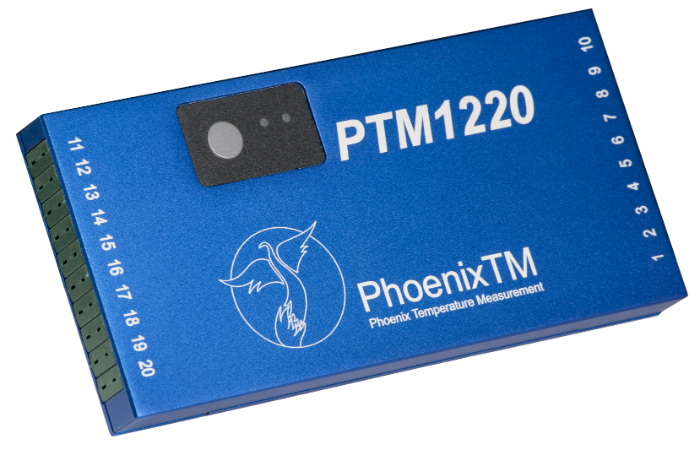
The data logger shown in Figure 3 has been designed specifically to meet the CQI-9 TUS requirements offering a +/- (0.5°F (0.3°C) accuracy (K & N). Models ranging from 6 to 20 channels can be provided with a variety of noble and base metal thermocouple options (types K, N, R, S, B) to suit measurement temperature and accuracy demands (AMS2750E and CQI-9).
Mixed thermocouple inputs can be provided to support the process specific requirements and also allow the use of the data logger to perform system accuracy testing (SAT) to complement the TUS.
Innovative Thermal Barrier Design

CQI-9 covers a wide range of thermal heat treatment processes and as such the thermal protection for the data logger will vary significantly. A comprehensive range of thermal barrier solutions can be provided to meet specific process temperature requirements and space limitations. Figure 4 shows a unique octagonal thermal barrier designed to fit within the boundaries of the product tray/survey frame used to perform a TUS using the “plane method” (See “Thermocouple Measurement Positions (TUS)” below in this article.). The design ensures maximum thermal performance within the confines of a restricted product tray/basket.
Live Radio TUS Communication

The data logger is available with a unique 2-way wireless RF system option allowing live monitoring of temperatures as the system travels through the furnace. Analysis of process data at each TUS level can be done live allowing full efficient control of the TUS process. Furthermore, if necessary, by using the RF system, it is possible to communicate with the logger installed in the barrier to reset/download at any point pre-, during, and post-TUS. In many processes, there will be locations where it is physically impossible to transmit a strong RF signal. With conventional systems, this results in process data gaps. For the system shown in Figure 2, this is prevented using a unique fully automatic “catch up” feature.
Any data that is missed will be sent when the RF signal is re-established, guaranteeing 100% data transfer.
Thermocouple Options (TUS)
In accordance with the CQI-9 standard (Tables 3.1.3 / 3.1.5), thermocouples supplied with the data logger, whether expendable or nonexpendable, meet the specification requirements of accuracy +/-2.0°F (+/-1.1°C) or 0.4%. Calibration certificates can be offered to allow the creation of thermocouple correction factor files to be generated and automatically applied to the TUS data within the PhoenixTM Thermal View Survey Software. Care must be taken by the operator to ensure that usage of thermocouples complies with the recommended TUS life expectancies and repeat calibration frequencies. Before first use, thermocouples must be calibrated with a working temperature range interval not greater than 250°F (150°C). Replacement or recalibration of noble metal (B, R or S) thermocouples is required every 2 years. For non-expendable base metal (K, N, J, E), thermocouples replacement should be after 180 uses <1796°F (980°C) or 90 uses >1796°F (980°C). For expendable base metal (K, N, J, E), thermocouples replacement should be after 15 uses <1796°F (980°C) or 1 use >1796°F (980°C). Note that base metal thermocouples should not be recalibrated.
Thermocouple Measurement Positions (TUS)
To perform the TUS survey, a TUS frame needs to be constructed to locate the thermocouples over the standard work zone to match the form of the furnace. The TUS may be performed in either an empty furnace in which case thermocouples should be securely fixed as shown in Figure 6. A heat sink (thermal mass fixed to thermocouple tip) can be used to create a thermal load to match the normal product heating characteristics. Alternatively, the thermocouples should be buried in the load/filled product basket. See Figure 6 to see schematics of TUS Frames for a box and cylindrical batch furnace with CQI-9-quoted number of thermocouples required to match void volume (Volumetric Method Table 3.4.1).
Fig 6: TUS Thermocouple Test Rigs. Required number of thermocouples: 1) Work Volume < 0.1 m³ (3 ft³) = 5; 2) Work Volume 0.1 to 8.5 m³ (3 to 300 ft³) = 9; 3) Work Volume > 8.5 m³ one thermocouple for every 3 m³ (105 ft³). (Click on the images for larger display.)
Fig. 7.1, 7.2. PhoenixTM system showing 9 Point TUS survey rig and Thermal View Software TUS frame library file showing as part of TUS report exactly where thermocouples are positioned. (Click on the images for larger display.)
For continuous conveyorized furnaces, it is recommended that an alternative thermocouple test rig is employed called the “plane method”. Since the system travels through the furnace it is only necessary to monitor the temperature uniformity over a 2-dimensional plane/slice of the furnace (Figure 8). The required number and location of thermocouples are shown in Table 1 (CQI-9 Table 3.4.2).
(Click on the images for larger display.)
Table 1: Required thermocouples and locations for differing work zones (Plane Method)

“Thru-Process” Temperature Uniformity Survey (TUS) Data Analysis and Reporting
Operating the PhoenixTM System with RF Telemetry, TUS data is transferred from the furnace directly back to the monitoring PC where, at each survey level, temperature stabilization and temperature overshoot can be monitored live, with thermocouple and logger correction factors applied. The Thermal View Survey software generates TUS reports which comply with the requirements of AMS2750E/CQI-9 standards.
As defined in CQI-9 (Section 3.4) for furnace with an operating temperature range ≤ 305°F (170°C), one setpoint temperature (TUS level) within the operating temperature range is required. If the operating temperature of the qualified work zone is greater than 305°F (170°C), then the minimum and maximum temperatures of the operating temperatures range shall be tested.
The TUS levels can be automatically set up in the TUS analysis software. Figure 9 shows both the TUS level file and TUS levels applied against the TUS survey trace.
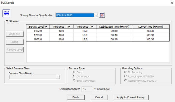

Fig 9.1, 9.2 PhoenixTM Thermal View Survey Software showing TUS Level set-up and application to TUS trace.
Within CQI-9, there is a very prescriptive list of what should be contained in the TUS report (Section 3.4.9).
To comply with all said requirements, the software package provides a comprehensive reporting package as shown below.
Fig 10.1, 10.2, 10.3. TUS Report showing a TUS profile at three set survey temperatures (graphical and numerical data). The probe map shows exactly where each thermocouple is located and easy trace identification. A detailed TUS report is generated, meeting full CQI-9 reporting requirements. (Click on the images for larger display.)
Overview
The PhoenixTM Thru-Process TUS System provides a versatile solution for performing product temperature profiling and furnace surveying in industrial heat treatment meeting all TUS requirements of CQI-9 within the automotive manufacturing industry, providing the means to understand, control, optimize and certify the heat treat process.