Heat treat industry veterans Wally Bamford, Chairman of HARPER INTERNATIONAL and founding partner of CAN-ENG, along with William R. Jones, CEO of the Solar Atmospheres group of companies, discussed a cooperative exchange of business benchmarks between Can-Eng, Harper International, and Solar Manufacturing, Inc. The purpose of this innovative business data exchange was to review operating parameters such as cost of materials, engineering and manufacturing labor rates, sales, marketing, R&D, and other cost centers. Since each of the companies is in the furnace manufacturing business, yet not competitors, it was agreed that an exchange of information would be helpful in improving each companies’ operations and identifying efficiencies. The most recent management team meeting took place in Niagara Falls, Ontario, Canada, where the photo associated with this release was taken.
Photo Courtesy of Solar Manufacturing, Inc.
L to R: Michael Klauck, President, Can-Eng Furnaces International Ltd.; James Nagy, President, Solar Manufacturing, Inc.; Scott Jacoby, Controller, Solar Manufacturing; Diane Weller, Controller, Can-Eng; Mark Young, Vice President, Purchasing and Procurement, Can-Eng; Wally Bamford, Chairman, Harper International; and William R. Jones, CEO, Solar Atmospheres Group of Companies.
This is the third in a series of articles by AMS 2750 expert, Jason Schulze. Please submit your AMS 2750 questions for Jason to Doug@HeatTreatToday.com.
Introduction
Of all the changes made to AMS2750 through the years, the Alternate Systems Accuracy Test (ALT SAT) is arguably the one that has had the largest impact within the heat treat industry. The requirements for the ALT SAT, as presented in AMS2750E, make up just 0.008% of the specification as a whole; yet these requirements account for an inordinate amount of time spent on discussion and debate.
Below, we’ll discuss the requirements of the ALT SAT as they are presented in both AMS2750E, and in the Nadcap Pyrometry Guide.
ALT SAT Applicability
Prior to revision E of AMS2750, a load thermocouple that was single-use, or which was replaced more often than the applicable SAT frequency, did not require an SAT of any kind. During the time period when Revision D was in effect, the Alternate SAT did not exist. This meant that if you used a load thermocouple and had a documented single-use statement or replacement schedule, which ensured the usage did not exceed the applicable SAT frequency within your internal procedures, that particular load sensor was not subject to the SAT requirements of AMS2750D.
AMS2750D page 14, paragraph 3.4.1.2
3.4.1.2 An SAT is not required for sensors whose only function is over-temperature control, load sensors that are limited to a single use (one furnace load/cycle), sensors not used for acceptance as part of production heat treatment, or load sensors whose replacement frequency is shorter than the SAT frequency. See 3.1.8.4 and 3.1.8.5.
When AMS2750E replaced AMS2750D, the ALT SAT was introduced. In addition to the ALT SAT, paragraphs 3.4.4 through 3.4.4.3 were also inserted:
AMS2750E pg 19, para 3.4.4
3.4.4 The SAT can be accomplished using any one of 3 methods:
3.4.4.1 Perform an SAT following the requirments in 3.4.5
3.4.4.2 Alternate SAT process defined in 3.4.6
3.4.4.3 SAT Waiver process, as described in 3.4.7
By stating that the SAT “…can be accomplished using any one of 3 methods”, this section has often been misinterpreted to mean that a supplier may simply choose which type of SAT they wish to implement. This is not the case.
An ALT SAT must be performed on any thermocouple that is either
single use, or
replaced more often that the applicable SAT frequency.
Throughout the industry, these two items typically apply to load thermocouples. As an example, let’s assume that a non-expendable load thermocouple is used in a furnace that is designated as a Type A, Class 5 furnace. This would put the standard SAT frequency at quarterly (no SAT extension & parts-furnace). If the non-expendable load thermocouple that was used had a documented replacement frequency of monthly, the ALT SAT requirements would apply to this particular load thermocouple.
In the example above, a supplier could not accomplish the SAT “…using any one of the 3 methods” – the ALT SAT requirements would be required for that particular load thermocouple system and would need to be accounted for in the supplier’s internal pyrometry procedure.
ALT SAT Requirements
The ALT SAT requirements can be split up into a single main requirement and two sub-requirements which suppliers may choose to implement. The main requirement is:
Calibration of instruments at the point at which the sensor is connected.
This means that, wherever the thermocouple is connected directly, instrument calibration must take place at this point. Let’s look at a vacuum furnace as an example.
Vacuum Furnace showing Location A and Location B for an Alternate SAT (photo courtesy: PVT Inc.)
Location A indicates where load thermocouples will be plugged in directly. Location B is where the extension wire from inside the furnace travels to the outside of the furnace and then on to the recording instruments. Location A is where the calibration of the recording instrument must take place per the ALT SAT requirements. This requirement in no way changes the standard requirements for instrument calibrations as they are presented in AMS2750E; it only specifies exactly where the instrument calibration must take place within the furnace sensor system. Your internal pyrometry procedure must state that this is a requirement.
The next paragraphs, 3.4.6.1.1 & 3.4.6.1.2, are where the supplier must read and understand both paragraphs in order to make a choice regarding which option best suits their furnace set-up and production. Let’s break both paragraphs down.
Option Number 1
3.4.6.1.1 - Establish appropriate calibration limits for sensors which when combined with the calibration of the instrument/lead wire and connector, will meet the SAT requirements of Table 6 or 7, as appropriate.
There are several ways to go about conforming to this paragraph. Keep in mind, that when choosing an option you are dealing with 2 variables; the error of the instrument which records the thermocouples in question and the error of the thermocouples themselves.
a) This option relieves you of one of the variables stated above. When calibrating your instruments which the thermocouples are plugged in to, ensure there is absolutely no error at all. Adjustments (offsets) may need to be made to accomplish this. This means that, if you do not permit offsets currently, you will either need to account for them in your procedures or choose option “b” below. Once you’ve established that your instrument has no error, you restrict the error of the thermocouples you purchase not to exceed the appropriate SAT difference stated in Table 6 or 7.
As an example, let’s assume you have a vacuum furnace that uses 2 load thermocouples which are single use only. The furnace is classified as a Type A, Class 2 furnace – this means the Maximum SAT difference is ±3°F or 0.3% of the reading. You would ensure that the recording instrument for those 2 channels recording the load temperature have no error. Then, order load thermocouples which have an error of ±3°F or 0.3% of the reading, or less.
b) This option is most attractive to those who do not wish to allow offsets within their heat treat operation. To accomplish this, you compare the error of the specific channels of the instrument the thermocouples in question plug into, to the error of the thermocouples themselves. The resulting value cannot exceed the maximum error permitted for the appropriate furnace class. Internal pyrometry procedures specifically state how thermocouple wire will be received and the ALT SAT calculation accomplished prior to releasing the thermocouple wire to production. There are two variables that must be verified in this option. Anytime one of these two variables change, the calculation must be obtained. The Nadcap Pyrometry Reference Guide requires that this calculation be evaluated at the instrument (chart recorder) calibration points (min, max & middle 1/3rd.)
Overview of a Calculation – Single Temperature
For Your Consideration
There has been some confusion in the industry that the ALT SAT process, specifically Option B above, must be accomplished at the furnace. This misunderstanding includes suppliers using a Field Test Instrument to simulate the min, max and middle 1/3rd of the instrument calibration temperatures in an effort to obtain the error of the instrument channels in question. This amounts to nothing more than an additional instrument calibration; one could simply obtain the error from the current instrument calibration instead of performing extra work at the furnace.
Option A and B above would be performed as a desk operation; none of the tasks would be performed at the actual furnace.
Conclusion
The ALT SAT process has been successfully implemented by many suppliers in the Aerospace Industry; both Nadcap approved and non-Nadcap. As with any AMS2750E process, detailed procedures and training are key to executing the ALT SAT process.
Submit Your Questions
Please feel free to submit your questions and I will answer appropriately in future articles. Submit your questions by sending an email to doug@heattreattoday.com.
Welcome to another episode of Heat Treat Radio, a periodic podcast where Heat Treat Radio host, Doug Glenn, discusses cutting-edge topics with industry-leading personalities. Below, you can either listen to the podcast by clicking on the audio play button, or you can read an edited version of the transcript. To see a complete list of other Heat Treat Radio episodes, click here.
Audio: Former Bodycote CEO Re-Enters Heat Treat Market
In this conversation, Heat Treat Radio host, Doug Glenn, interviews John Hubbard, longtime CEO of Bodycote who retired in 2009 and has recently re-entered the market with an aggressive capital investment company located in Baltimore, Maryland. This 20-minute Heat Treat Radio interview gives you all the important news about what Mr. Hubbard and theCalvert Street Capital Partners (CSCP) are planning. To date, CSCP, under the leadership of Mr. Hubbard, have snagged top talent from the industry, including Mike Sobieski and Don Longenette, and are actively pursuing the acquisition of well-established and profitable commercial heat treat across North America.
Our aerospace, automotive, medical, and energy manufacturers with in-house heat treats will find it encouraging to hear what John has to offer.
Click the play button below to listen.
Doug Glenn, Heat Treat Todaypublisher and Heat Treat Radio host.
To find other Heat Treat Radio episodes, go to www.heattreattoday.com/radio and look in the list of Heat Treat Radio episodes listed.
Mr. William Jones, CEO of the Solar Atmosphere Group of Companies, listened with interest to the recent Heat Treat Radio podcast featuring Phoenix Heat Treating president, Peter Hushek. Peter introduced a new 3D TUS tool, Virtual Visual Surveys.
Below, Mr. Jones offers his comments about this new tool and TUS practices in general.
If you’d like to listen to the Heat Treat Radio episode that sparked these comments, click here.
Please note that immediately following Mr. Jones’ comments is a response from Peter Hushek.
Unedited comments from Mr. Bill Jones, CEO, Solar Atmospheres & Solar Manufacturing…
Like Peter Hushek we have been in this TUS business for more time than we like to remember. So, most up to date HT companies track our TUS data on paperless video recorders and down load onto an Excel spread sheet and plot out the data a minimum of every 30 seconds. This is done with a preprogrammed digital temperature controller thru the necessary ramps, soaks, and set points. The Excel spread sheets also contains all the survey and controller TC correction factors. Prior to the survey each data point contains the preset temperature controller PID parameters. All survey TC’s are set into their preset locations per AMS 2750E with careful notation to position and correct TC length and care for equal hot / cold lengths. Prior to survey each electronic instrument is checked with a calibrated thermocouple millivolt run-up box and each instrument calibrated. Normally midafternoon each furnace under test is set up thus and the survey to run preprogrammed overnight. Our QC department downloads the data, reviews and makes the pass fail decision, within a few hours, the next day. If the TUS failed back to maintenance to look into the issues, make corrections and rerun the TUS. Problems are not always furnace related but thermocouple, TC position, jack panel, jack panel wiring, instrumentation, and numerous other issues. I view the VVS 3D presentation as an aide but only part of the story”.
William R. Jones, CEO, FASM Solar Atmospheres Inc. Souderton, Pa.
And Peter Hushek’s unedited response to Mr. Jones’ comments…
In regards to the response from the listener I can say he makes some valid points. There are many issues that can affect the outcome of a TUS. We realize that the evaluation of the furnace uniformity involves many aspects and we are only addressing the data generated by the process. We believe that when companies begin the process of actual data analytics they will become more aware of the process and improve the quality of their processing as a result. VVS is only beginning to scratch the surface of the data flow that occurs daily in processing companies. We look to greater innovation through customer supplier interface as well and technological improvements that can be used as feed stock to improve future generations of this software. We are only starting the process and I hope the market realizes that this is not a static process or company.
If you haven’t done so already, clicking here to listen to the Heat Treat Radio episode being discussed above.
Long-time heat treating expert, Peter Huskek of Phoenix Heat Treating, a fourth generation commercial heat treating institution, is branching out into the computer simulation arena with a very impressive, 3D temperature uniformity survey (TUS) reporting tool called Virtual Visual Surveys (www.virtualvisualsurveys.com). What Mr. Hushek and his team, including key developer Jeff Murch, have developed under the company name of Thermal Innovation Technologies, Inc., is a 3D visualization tool capable of showing furnace operators what their furnace uniformity looks like. This 3D visualization software helps quality personnel know if a furnace will pass a TUS, and if not why. It also allows maintenance personnel the opportunity to isolate and diagnose problem areas within the work area of the furnace. The 3D visualization package is offered as a service. For more information, visit www.virtualvisualsurveys.com.
EDM is a tried and accepted, economical method of machining many different tool steels. This method of EDM machining can produce very intricate shapes can be machined to very accurate sizes.
However there are problems which can (and do) occur that are associated with the EDM process in relation to the final heat treatment of the die or tool.
It is most important for both the toolmaker and the heat treater to have an understanding of the resulting metallurgy and surface layer construction in relation to the final heat treatment.
Below is shown a schematic of both system principle and the resulting operation of the EDM process.
Figure 1. Schematic of the principle of the EDM procedure. (Courtesy of KMCT College, India)
Figure 2: Schematic of the principle of EDM operation. (Courtesy JD Online, KMCT College India)
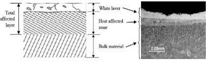
The final EDM layer is generally seen (microscopically) as follows;
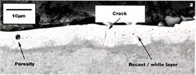
The surface layer which is also known as The Recast Layer. This layer is at the immediate surface and is generally very hard and brittle. (Remember it has seen a very high temperature, which is up to the point of melting). The objective of the EDM is to vaporize the surface layer and remove it. But it is, in reality a melted layer which will cool rapidly at the surface of the tool. The surface is now in a highly residual and stress full condition which can and very often does, lead to cracking, heat checking and ultimately premature surface failure. More often than not, it is the heat treater who is blamed, no matter how careful the heat treater has treated the tool.
Figure 3: Characteristic layers of a subsurface.
Figure 4: The recast layer is a layer of untempered martensite with a high crack risk potential.
The untempered martensite transformation occurs due to the heat sink that takes place from the generated heat of the EDM. The generated heat energy diffuses into the body of the tool and creates the appropriate transformation from austenite into martensite because of the rate of cooling. This will give rise to a stressful potential crack occurrence condition (due to the untempered, unstable m fresh martensite). Hardness values of the untempered martensite layer can be as high as 62 HRC (depending of course on the chemistry of the steel).
Figure 5: Illustration of the cracked untempered martensite after EDM.
Below the untempered martensite layer will be another layer of what can be a tempered martensite layer with hardness values (once again depending on the steel chemistry) in the region of up to 52 to 54HRC.
Below that layer on tempered martensite will be the original hardness and microstructure of the base material.
The recast layer is the dangerous layer, because not all of the melted layer has been flushed away. When a failed/cracked sample is etched, the recast layer will be seen as a white layer (do not confuse with the white layer of a nitrided surface).
What can be done to prevent (or at least reduce the risk of potential cracking)? The only simple procedure (but with no guarantee) that can reduce the risk of cracking, would be to temper the component immediately after the EDM procedure.
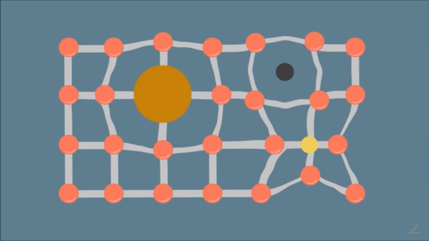
Steel is primarily iron with up to 1% carbon, plus other alloying additions (generally totalling less than 5%).
A steel composition can be thought of as a recipe; different amounts of each ingredient make up your final product. In steel these ingredients are known as alloying additions and can affect the steel in different ways. We can affect the:
Properties of steels.
strength
hardness
toughness
ductility
fatigue
formability
machinability
weldability, and
corrosion resistance.
The addition of carbon to iron is probably the most important addition in steels which makes ‘The Iron Carbon Equilibrium Diagram’ very useful. Equilibrium means that enough time has been allowed on heating and cooling for any reactions to fully complete.
Typical Iron Carbon Diagram
In a steel <723°C, different structures are present and depending on the carbon content we can have at <0.8% Carbon – ferrite and pearlite, at 0.8% carbon – pearlite and >0.8% carbon – pearlite and cementite.
While the iron carbon diagram describes the structures of steel under equilibrium conditions, two further diagrams can be used when faster cooling rates are used; these are the CCT (continuous cooling transformation) diagram and the TTT (time temperature transformation) diagram. Both of these diagrams are helpful in selecting the optimum steel and process parameters.
When we cool a steel at faster cooling rates we can achieve additional structures, these can be bainite and martensite. CCT and TTT help determine the structures achieved.
In metallurgy the hardenability of a steel is a key parameter and when we talk about hardenability in steels we are often describing how deep into the steel we can achieve hardening. If a steel is described as having a low hardenability this will mean that the steel will produce a shallower depth of hardness. Hardenability is not to be mistaken for hardness; when describing the hardness we are often looking at the microstructure achieved during cooling. For a given steel it can be assumed that the quicker the cooling rate the greater the chance of achieving a harder structure and if that steel has a high hardenability this hard structure will be present deeper into the thickness.
In metals there are atomic defects called dislocations, these dislocations reduce the strength of the metal. The principle of strengthening mechanisms is to reduce the ability of these dislocations to move through the metal, this can be achieved by:
Atomic dislocations within the metal potentially reduce the metal’s strength.
Grain Size; the grains can interact with the dislocations preventing further movement. If we reduce the grain size we can increase the number of grains interacting with the dislocations, preventing movement and thus strengthening the metal.
Cold work introduces a large amount of strain into the metal; this strain interacts with the dislocations strain field, impeding the movement of the dislocations.
Solid solution strengthening is applied when we add other chemical elements to a metal. Addition of these elements can either be called interstitial or substitutional solid solution strengthening and will cause distortion in the atomic structure, restricting the dislocation movement and strengthening the steel.
Dispersion or precipitation strengthening is highly related to the structure of the metal and takes place when a phase is finely precipitated through a softer matrix. This precipitate acts as a barrier to dislocation movement.
The next in the series will be Steel Making and Casting.
Special thanks goes to Gary Berwick of Dry Coolers, one of our first (and best) advertisers, for informing Heat Treat Today about the below article in Airways Magazine.
MIAMI — The National Transportation Safety Board (NTSB) issued and Investigative Update of American Airlines flight AA383, which caught fire on runway 28R at Chicago O’Hare International Airport after aborting its take-off.
The report states that the right engine number 2 stage high pressure turbine (HPT) disk failed and fractured into at least four pieces. A large disk fragment landed in a UPS warehouse located about 2,920 feet (890 meters) from the aircraft.
Within the aerospace heat treating field, Nadcap heat treat audits are a necessary part of doing business. The requirement to obtain Nadcap approval is “flowed down” from primes like Boeing and Airbus to sub-tier suppliers and these approvals must be maintained. Nadcap heat treat audits are typically more difficult than other audits and this is due primarily to the inclusion of pyrometry.
My name is Jason Schulze. I’m a metallurgical engineer with over 20 years in the aerospace industry. I’ve been exposed to Nadcap in multiple commodities, although often focused in heat treat. I work with companies to insource and improve special processes, perform gap-analysis and internal audits as well as gain Nadcap approval. I am also contracted by PRI as an eQualern Instructor and teach multiple courses including pyrometry.
In the upcoming series of Heat Treat Today articles, I’ll present specific subjects related to Nadcap heat treat audits and pyrometry. In subsequent articles, I hope to be answering your questions – questions submitted by our readers.
In this initial article, I’ll focus on AMS2750E comprehension as well as offering a Quality based perspective with regards to accounting for each requirement within the specification.
Understanding AMS2750E
As with any specification, it must be read carefully. It would do no good to read the specification and attempt to implement it if you do not understand the material. On a scale of 1-10, with 1being zero knowledge of pyrometry, someone reading AMS2750E for the first time would need to be at least a 5 in order to properly comprehend and implement the AMS2750E Specification.
Most quality engineers are familiar with the term “bubbling” as it relates to blue prints. Bubbling a print is a practice in which each requirement is assigned a sequential number. Once this is done on the print, it is then logged onto a form which contains the designated number, its associated requirements, the subsequent result, and an accept/reject notice. Typically, this is done on machined parts that may have an intermediate process (such as heat treat) involved in their manufacture. When an intermediate process is performed, the specification is simply listed as the requirement and an accept designation is applied. The specification itself is not bubbled, but read by an engineer, and the applicable requirements flowed down.
My method is to bubble the specification itself. Take each requirement out of the specification and assign it a sequential number. Let’s call them “Characteristic Requirements”. Some paragraphs may have several requirements within a single paragraph; each would be separated and assigned its own sequential number. Let’s look at an example of this:
AMS2750E PG 19, PARA 3.4.5.1:
“The displayed temperature indication and/or recording of the sensor being tested as used in production, with appropriate offsets or correction factors, at any operating temperature, shall be compared with the corrected temperature indication of the test sensor on a test instrument”
It may seem that a single requirement is being put forward; but there are actually 7 contained within this one paragraph.
The displayed temperature indication…
and/or recording of the sensor being tested…
as used in production…
with appropriate offsets or correction factors [option for either]
at any operating temperature…
shall be compared with the corrected temperature indication of the test sensor…
on a test instrument.
I have performed this task on both AMS2750D and AMS2750E. Revision E ended with 513 characteristic requirements, including tables and figures. Once bubbled, each requirement must be accounted for as they apply to your operations. For example, any requirement regarding a retort furnace would be designated “N/A” if your operation employed only vacuum furnaces. Of course, the continuing issue of comprehension arises at each step of this process. If you have a poor understanding of pyrometry it will be difficult to bubble AMS2750E, and nearly impossible to successfully complete the process of showing conformance.
AMS2750E Training
By training, I’m referring to comprehension of AMS2750E itself. Instruction on how to properly calibrate an instrument, perform an SAT or wire up a rack to perform a TUS will be much easier once AMS2750E is understood.
Several courses are offered through multiple companies. Choosing one where you will obtain practical and sound advice concerning your specific operation as it relates to AMS2750E is the key. Get pyrometry training from an engineer who not only has performed the work in accordance with AMS2750E, but more importantly, has been involved in the actual manufacturing of heat treated hardware and has been through a live Nadcap audit. Knowledge in pyrometry may be one thing; its real-time application within an actual production environment is entirely different – and invaluable.
Conclusion
Ensure your comprehension of AMS2750E is in line with Nadcap’s expectations; training will be the key. This will expedite your success in implementing AMS2750E as it applies to Nadcap.
Submit Your Questions
Please feel free to submit your questions and I will answer appropriately in future articles. Email your questions to Doug@HeatTreatToday.com.
The cost of poor quality — with an eye toward eliminating it — was the topic of discussion at a recent heat treat industry conference (Furnaces North America). Todd Wenzel, President of Bluestreak|Throughput Consulting, made the presentation on October 4th in Nashville. By clicking on the image below, you’ll be taken to a post-event re-recording of the presentation.