Brandon Glenn

Heat Treat Radio #45: Justin Rydzewski on CQI-9 Rev.4 (Part 2 of 4) – HTSAs & Job Audits

Heat Treat Radio host, Doug Glenn, conducts Part 2 of this 4-part series with James Hawthorne of Acument Global Technologies and Justin Rydzewski of Controls Service, Inc. about Revision 4 of CQI-9. This time, the conversation focuses around heat treat system assessments and job audits.

You are about to listen to the 2nd episode in a 4-part series on CQI-9 Rev. 4.  You can find the previous episodes at www.heattreattoday.com/radio.

Below, you can either listen to the podcast by clicking on the audio play button, or you can read an edited version of the transcript.


The following transcript has been edited for your reading enjoyment.

Doug Glenn (DG):  Welcome to Heat Treat Radio.  I am here today with Justin Rydzewski from Controls Service, and a new guest we’re going to introduce to you in just a moment, Mr. James Hawthorne from Acument Global Technologies.  We are going to be talking about CQI-9.  This is our second in a four podcast series on the new Revision 4 of CQI-9.  We want to welcome our guests today.  As I mentioned, Justin is from Controls Service, in Livonia, where he is the director of sales and marketing.  Justin was actively involved on the committee that wrote Rev 4.

Justin Rydzewski (JR):  That’s correct.  I was an active participant in coauthoring the fourth edition.  My most significant contributions were to the pyrometry section.

DG:  Correct.  And pyrometry was what we talked about last time.  So, welcome back.  We are also welcoming James Hawthorne.    I want you to tell folks about yourself, but as I mentioned, you’re with Acument Global Technologies, a Fontana Groupo company, which I believe is an Italian based company, that is located in Michigan, with its  headquarters located in Sterling Heights.  My understanding is you are the heat treat specialist at that company.  If you don’t mind, please tell us a little bit about  the company and yourself as well as your involvement on the CQI-9 committee.

James Hawthorne (JH):  I work for Acument Global Technologies.  I am the heat treat specialist for our North American facilities.  I handle the heat treat systems, the system’s compliance, and quality assurance for the heat treats within our organization.  Acument has been around many, many years.  We make fasteners – nuts, bolts, rivets, washers – for the auto industry.  We make it for off-highway equipment, things like tractors and bulldozers and whatnot, and we also do building and construction fasteners, as well as things that are holding bridges together, and roller coasters — you name it, we probably have a fastener in it.

[blockquote author=”James Hawthorne, Acument Global Technologies” style=”1″]We’ve been working on this document for quite some time.  Through a lot of expertise and many, many, many work hours, I believe we’ve put together a really good product for the industry.[/blockquote]

DG:  We appreciate that!  We were talking before we hit the record button how the world would be a worse place if fasteners weren’t holding stuff together.  I do want to mention, before you go on, that according to the Acument website, the company is described as the world’s most innovative manufacturer of value-added screws, bolts, nuts and cold formed components.

Please continue.  Tell us about you and your role on CQI-9.

JH:  I’ve been in the heat treating industry for over 25 years.  My formal education includes metallography and statistical process control.  I’ve held positions in heat treat including maintenance, working in the laboratory, working in supervision, and now I work in the corporate capacity, which is what led me into AIAG.  We are a member company, and I was brought in to add as much value and knowledge as I could, based on my experiences.  Currently, I am the chairman of the technical committee.  We’ve been working on this document for quite some time.  Through a lot of expertise and many, many, many work hours, I believe we’ve put together a really good product for the industry.

DG:  Basically, you’re the technical director of the committee?

James Hawthorne
Corporate Heat Treat Specialist,
Acument Global Technologies

JH:  The committee chairman.  The important part is to try to keep everybody on task; you’re more of a task manager at that point.  You get a lot of smart people in a room, and trying to corral that intelligence is not difficult; it’s just making sure that we stay in the right lane, get to the bottom of what we’re trying to get to, and complete the specific task in the moment.

DG:  I asked Justin this the last time, and I’d like to ask you, too, just to get your perspective.  How would you explain CQI-9 to someone who has essentially zero understanding of what it is?

JH:  First I’d start with the acronym itself.  CQI-9 is Continuous Quality Improvement.  The purpose behind it is to put together a system that will help you manage and control your process, and at the end of it, the product that you’re delivering to the end user.  The intent is to give you those guidelines to help avoid potential spills or escapes or whatever else may come with that.

DG:  Right, any of the hurdles in the process itself.  It’s mostly heat treat related, yes?  Or is there more than just heat treat there?

JH:  It is the entire system of heat treat.  If you look at the heat treat system assessment, the first portion of it is quality based.  The second portion (section 2) is the floor responsibilities, things that are on task that are being completed.  And third, you get into the maintenance and the pyrometry portion of it, very specific to the pyrometry and very specific to atmosphere control.  At the end of it, there are some very specific induction questions, because when it comes to induction, there is no real furnace at that point, so you want to focus on those key elements of induction.

DG:  Justin, the last time we talked about this, we tried to break this down to keep it simple – the CQI-9 and the four basic sections.  Very briefly, let’s review those and then we’re going to jump into talking about heat treat system assessments and job audits.  Can you give us the four categories?

JR:   CQI-9 is broken down into a few sections and one of the reasons for that, per our conversation last time, it is not exactly like an AMS2750, which is a pyrometry standard.  Instead, this is a system assessment.  It is meant to assess an entire system of heat treat.  It includes a multitude of sections that address the system as a whole.  It starts with your heat treat system assessment, which often utilizes an acronym of HTSA, then you have a pyrometry section, then a job audit, and then your process tables and various different support elements, like a glossary of terms, instructions sheets, and whatnot.  But the four are the HTSA, pyrometry, job audit and process tables.

Read/listen to the first episode. Click the image above.

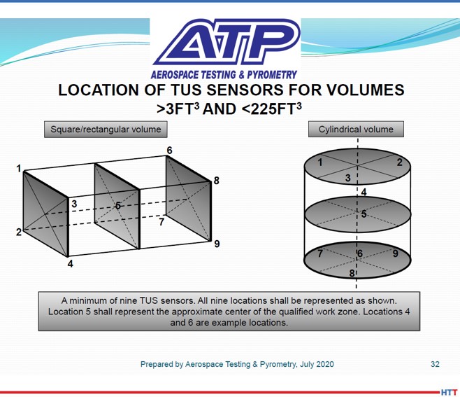
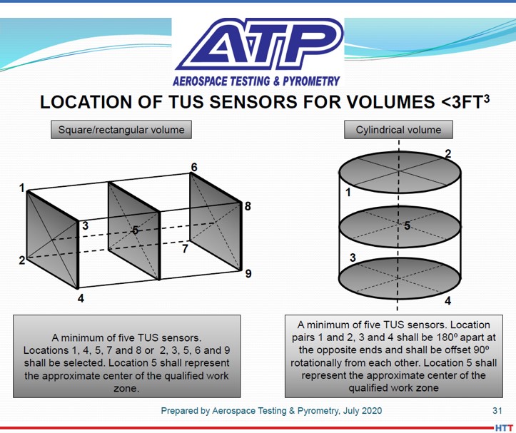
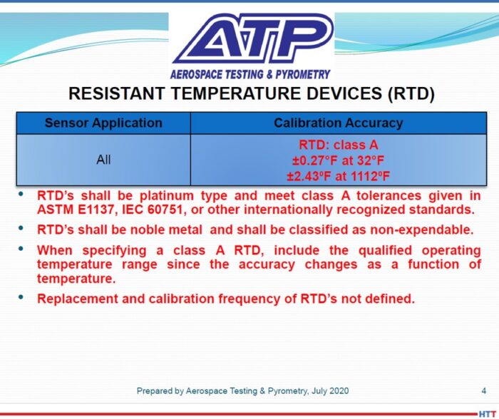
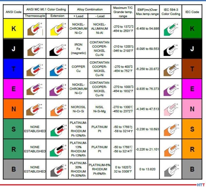
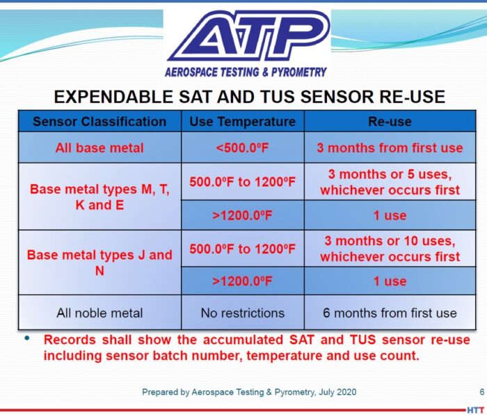
DG:  As we mentioned last time, Justin, you and I talked down through the pyrometry section which covered things like sensors, thermocouples, calibration, SATs and TUSs.  If you, our audience, are interested in that information, you’d want to go back to the first episode.

James, we’d like to pick your brain a bit on this.  Let’s jump into some questions on the HTSAs, as we’ll refer to them, heat treat system assessments, and job audits.  Let me ask you this to start off.  Let’s go right to the basics: What is an HTSA and what is its purpose?

JH:  HTSA, heat treat system assessment, is a tool that has been developed to help you evaluate how you manage your heat treat system for effectiveness – effectiveness in quality management, effectiveness in the floor responsibilities.  Like I mentioned earlier, understanding that through aspects of training and training effectiveness and into the final section of atmospheric control and atmosphere management and reaction to those.  The purpose here is to have one system, one document that is the rules of engagement for doing heat treat in the automotive world.  What this does is, it allows the automotive industry to give you one spec, one thing to follow.  As opposed to having, say Ford, to give you ten questions where none of them are exactly the same as FCA or nine of them are the same as Ford motor company, where one of them have a specific question.  This encompasses all of those wants and needs from the auto industry to protect themselves, to protect the end user out there in the field that may be using that heat treated component.

DG:  How frequently does a heat treater need to conduct an HTSA?

JH:  The rules of engagement are annually.  On an annual basis you should be evaluating your system for compliance.  The beautiful thing about the HTSA is that it is a living document.  If you find any shortcomings in there, you have the ability to go back and update that and make it match what your reality is after you find the solution to the problem that may have come up while doing your assessment.

DG:  For clarification, these HTSAs, are they conducted by the company, or do they need to have a third party come in and conduct the HTSA annually?

JH:  That’s a great question.  There are no rules to having an independent body come in to do this assessment.  If you have the people that meet the criteria within your organization to do the HTSA, the system assessment along with the process table review and the job audit, you can do it within your own organization.  You just have to meet the criteria that is listed in the book, and these kinds of things are having experience in heat treat, which is the number one thing you must have to be the lead auditor of a heat treat, the understanding of quality core tools and having that audit experience.  Those are the things that you have to do to be able to successfully do an audit and it meet the intent of CQI9.

JR: I believe the intended purpose of the HTSA was initially for it to be supported internally by the organization.  That was the intent of it.  We commonly refer to the HTSA as a self assessment.

DG:  That makes sense.  I assume that when the auditor comes in, he may audit how you did your HTSA, to make sure that it was done well, and all that good stuff.

So the outcome of HTSA is going to be pass, fail, miserably fail; what are the possible outcomes?  I know we’ve talked about “Not Satisfactory” and “Needs Immediate Action.”  I want to deal with those differences, but what are the outcomes?

JH:  “Not Satisfactory” is where you don’t meet the intent of the shall within the related HTSA question.  Now, that could be a simple oversight where it’s very easily correctable- you put the proper things in place and you move on.  If you have something that could jeopardize final product quality, now you’re looking at something that may be a “Needs Immediate Action” and that “Needs Immediate Action” will be evaluated by the assessor and the heat treat organization as to what needs to be done.  CQI-9 does afford the heat treater with 90 days to correct any finding.  If it’s a “Needs Immediate Action,” there should be action to correct that finding immediately up to 90 days.  It’s also important to note that if it’s something that is going to jeopardize product quality, then there is a chance that it “Needs Immediate Action” will be extreme enough to where you have to stop processing – stop processing, fix the problem and then begin processing again.  But that goes to the evaluator.  You have to be able to evaluate that; and that’s one of the many reasons why we look at the assessor, or at least the lead assessor, being a heat treater, because he’s going to understand it, he’s going to know it.  For a commercial house, it’s very easy to have those people available.  In a captive house, maybe not so much, where you’ve got a lot of other things going on plus heat treat.

JR:  I don’t know if you recall or not, James, from the roll-out we had a question that came through, and I don’t know if we were actually able to address it, but they posed a question of why the heat treater was given a greater amount of focus than was in the previous edition.  Somehow, that was an element that required explaining because there was a question of a possibility for there to be issue with doing so.

JH:  If we go back to the conversations that we had about this, I think this was one of the topics we talked at length about, and the rationale behind the lead assessor.  Is it more important for that person to be a good auditor, or is it more important for that person to be a heat treater?  We’re not diminishing the need to have audit experience, at all.  The only difference is that we’re saying that the person that is going to be the lead auditor be a heat treater, because that heat treat experience is going to be much greater than somebody who has audit experience.  Where if an auditor goes out and he looks at every day is cold forming, for example, and how they make the fastener itself, well, when he gets to the heat treat portion of it, is he going to know what atmosphere control is?  Is he going to know what endothermic gas is?  This is the rationale behind this change – that these people are going to understand the language, and that’s the importance.

JR:  The key element is that it doesn’t mean that you don’t have to have the audit experience on that team.  That person is still needed, it’s just the focus shifts a bit.  It doesn’t mean that it is now absent.

DG:  Let’s move on to job audit, James.  It’s different than an HTSA, but what is a job audit and what is the purpose?

JH:  The job audit is the supplemental portion of the assessment process.  The job audit is where you would take apart and walk it through the system and then verify all of the evidence that you’ve put into the HTSA.  You walk the process; you go look at each point specific item based on the job audit flow, and you check: Did the operator check the right amount of pieces?  Does that match what you said in the HTSA?  Did they document their efforts on, let’s say, production report A and process report B, and is that what is represented in the HTSA?

The first part is the “truss,” then you’re verified.  Now, you’re doing some verifying in the HTSA, don’t get me wrong, but this is actually walking that part through the system and ensuring that every box was checked, every “T” crossed and every “I” dotted.

DG:  It sounds like the HTSA is more like the blueprint and the job audit is running a part through and making sure that we match up to the standard, so to speak.

JH:  Yes, sir.  And it’s verification of your reality.

DG:  Is there a requirement as far as frequency of job audits?  How often do you have to do those?

JH:  This is also annual.  You are required to do an automotive part.  I know that some customers might like to see their part in the job audit, but we don’t require it per customer.  If it’s an automotive part, I would say 95 – 99% in the industry, what you’re doing for one customer, you’re doing for every customer, in a 101 kind of standpoint.  There may be some special tests here or there, but overall, your system and your system’s management is going to be the same for one customer that it is for all customers.  If it’s right for one, you’ll do it for all.  And that’s the intent.  Do it with the one automotive customer, and then the next year, do a different part.

DG:  Do you find, in your practical experience, that people are doing more than one job audit a year?  It seems to me, it would make sense to do more than one, but I don’t know.

JH:  I guess it depends on the organization.  I know, for our organization, we do a job audit annually for each process employed.  I’ll give you an example of this.  We have a facility that has belt furnaces and it is neutral hardening.  So, we’ll do a job audit for the neutral hardening.  Then, we have induction in that facility, as well, so we’ll do one for induction.  And then there is stress relief post induction, and we’ll do one for that as well.  For us, in our organization, that’s how we manage it to accommodate the processes employed at our facility.

James Hawthorne and Justin Rydzewski speak about how the heat treat system assessment (HTSA) in CQI-9 has changed.

DG:  Let’s talk about the CQI-9 Rev 4.  What were the major changes to the HTSA requirements?

JH:  Right off the top, the big change was the format.  In the 3rd edition, you had one question that required one answer.  There were many shall statements inside that one question, so you were trying to answer a multifaceted question in one area.  Now, the HTSA is slightly different where you have one kind of overall question and then each shall statement is individually broken out and now you have to show effective evidence inside each one of those shall statements.  Talking through this, maybe it sounds a little odd, but I will tell you that it has cleaned up this document tremendously, where it makes it so much easier to walk the system and expose either your compliance or noncompliance to a shall statement.

DG:  I do have a question here.  You’ve mentioned it several times, but I just want to make sure our listeners understand this.  I assume you’re saying “shall” statements, as in “thou shalt do this and thou shalt do that,” correct?

JH:  That is absolutely correct.  From an auditor’s standpoint, there is a difference between shall and should.  Should is suggested, shall you will do.

DG:  Right.  Shall is a requirement, should is a strong suggestion, let’s say.

Any other changes in Rev 4 as far as the HTSA?

JH:  I would say that there are subtle changes to all of the HTSA questions.  Some of them are maybe not as significant as others, where it’s cleaning up the language or removing some wording just to make the question read clearer.  That clarity to the end user was one of the high priority items for our group when we were doing the writing of this document.

The big thing I would say for anybody using this document, whether or not they’re a seasoned veteran with 20 years of heat treating experience, anything short of reading this document and you’re not doing yourself any favors.  It’s important to walk the document.  It’s important to traverse the document, whether you do it in phases – grab the HTSA and read through it, and then maybe a week later go through another portion of it, especially if you’re getting to the point where your assessment is coming up to be due.  It provides a lot of information and a lot of guidance, and it will help you avoid any potential pitfalls.

[blocktext align=”right”]”DG:  So does that mean less time, hopefully?”         “JH:  100% yes.”[/blocktext]JR:  I would also agree in terms of the changes.  The most significant one is the formatting, far and away.  I think even in the CQI-9 expert analysis article that we did with you guys, Bob Ferry even noted that as the most notable change in his mind was the improved formatting there and how much easier it is now to capture all of those requirements, whereas before you’d have some long drawn out paragraph.   Before, you used to look at it and say that’s a requirement, but when you’d read it closer, you’d find five or six shall statements and multiple paragraphs and were given one box to provide an answer to.  That makes things complicated.  And there are several new requirements within the HTSA questions, but far and away, the changes are really to make it more clear, provide that additional guidance, and define more explicitly what the expectations are of those individual requirements.  To capture all of those, it’s going to take a read-through.  Some of them are minor, some of them are different, but there are new requirements.  There have been a few questions that were added that weren’t in previous ones; they have been expanded on, I should say.

DG:  It is a significant rewrite.  If you’ve done Rev 3, don’t assume you can fudge it.  Basically, start from scratch and go from there.  I think that’s the point taken.

So we’ve covered some of the major changes in HTSA.  How about in the job audit?  What are the major changes on the job audit side, James?

JH:  I would say that as far as major changes, there are not very significant changes.  I think that there were some subtle changes and some removal of questions that in the 3rd edition didn’t quite fit the intent of the job audit.  For example, it would ask you to go look at something like APQP process.  What did that look like?  In the HTSA, you’ve already covered that, and APQP information you may not find out on the floor.  You’re going to have bin tickets, bin tags, part travelers, production records and things of that nature, so the APQP process you won’t find out on a floor.  So, some of those things were dialed back to where that information wasn’t required to be looked at a second or third time.

DG:  Is it your estimation that a job audit under the 4th edition is going to take more time or less time than under the 3rd?  Does the documentation help us to do it more quickly?

JH:  I think evaluating the system and utilizing the job audit is going to be significantly easier; it’s more streamlined and it’s set up to allow you to traverse the process better than it was before.  In other words, more effectively and more efficiently.

DG:  So does that mean less time, hopefully?

JH:  100% yes.

DG:  I think that’s important.  I think that will help those who maybe have some hesitation about looking at Rev 4 because there is the possibility of saving some time.

JH:  I’ve had the luxury of performing six within our facilities, under Rev 4, and I will tell you that the job audit portion is certainly quicker and more efficient.  The HTSA takes a little bit longer because it’s new and the format is new, so aligning everything with what your reality is takes a little bit of time.  It certainly forces you not to assume, which I found to be a really amazing part of this process.  Our company’s systems are very, very common and all of our heat treat processes have the same work instructions.  That’s part of what my job is, is for that commonality across our plants.

Even though I am very intimate with all of our plants and very intimate with all of our processes, going through this process allowed me the opportunity to do it – and I feel do it very effectively – because at no point did I ever stop and assume that somebody was doing something.  It was like, Alright, I’m going to put in what your reality is, I’m going to write down what we’re doing.  And that was a great part of this process, for me.

DG:  I have a final question for you on this.  You know that you’re going to have some people that are going to be doing Rev 4, they’re going to be starting it and doing their initial assessment, if you will.  James, you’ve already done six at least in your plant.  What kind of guides would you give people to not overlook when they perform that initial assessment?

JH: First and foremost, read the question and make sure that your answer makes sense to you as a heat treater.  I would say, even more importantly, if you come across any word in this document that you’re 70% sure you know the meaning of, go to the glossary and use it.  It is a very intuitive tool in this document and those definitions are written as it pertains to this document.  If you need that guidance, if you need that nudge over a small hurdle that you’re dealing with based on what does this mean or how do I interpret this, go to the glossary first.  It is a GREAT tool.

JR:  I think that due to the fact that the 3rd edition had such a prolonged life on the street of 9 years, that’s going to allow someone to get rather efficient at doing that process of going through that HTSA.  You have a well-developed and worked-through system at that point, and when something comes along like the rewrite/4th edition and the HTSA, that is going to be very different; where the first few assessments that you perform to the 3rd edition may have taken X amount of time, I would compare that more so to how much time it’s going to take you for the 4th edition.  As heat treaters became efficient doing their HTSAs and that time pared down, all of a sudden now they’re given this 4th edition, and it could seem like it’s a lot by comparison. But it’s just something new.  You will get through it and you’ll start to gain speed overtime. And I think that the clarity and the ease of capturing these requirements within the 4th edition are going to outweigh the aspects of other things and it’s going to allow you a real good chance to turn over all those stones that perhaps have been assumptive, of sorts, over time.

DG:  The point being – don’t be discouraged if the first several assessments under Rev 4 take you a good bit of time.  It’s probably the same as when you were doing Rev 3: they took a lot of time but you get better and better and more efficient and ultimately, with the format you guys are providing in this Rev 4, it sounds like it’s going to be a much more beneficial outcome in the end.

JH:  Absolutely.  And to give you a time frame, 2–2 ½ days is what it was taking us to do an assessment at one of our facilities.  Now, it’s about 3 ½ days.  It’s not significantly longer, but to supplement the point that Justin was making, take your time.  Read through it and take your time.  It is important to make sure that we cross T’s and dot I’s, especially in our industry.  It is no place to shortcut.

JR:  It’s an interesting point that you made early on.  As you go through the development process here, you don’t want to forget about trialing what it is you’re suggesting that we do, like to put it through the worst to make sure that it’s doing what we intended it to do.  I thought it was a very interesting point that James had made in conversations with me through the development process about one element of the new formatting.  That from a scoring aspect, your scoring is going to be a little different than it was in the 3rd where you had one box for an answer to five shall statements, you now have five boxes with five opportunities for scoring that differently.  One question, in the previous edition, had one answer for satisfactory, not satisfactory, yada; in the new revision, you’re going to have five responses that are given.  So, it’s going to change the way you would ‘score’ it.  Is that how you would term it, James?

JH:  Evaluate it, score it, yes.  It’s important to understand that any heat treater doing this assessment for themselves should never get hung up on the number of findings, because the content could be so much worse.  If I have findings at one of our facilities where they have ten findings because they had blank spaces on a log that weren’t accounted for, and I had one plant that had one finding, but they were running 10% extra water in their quench oil, I would say that that’s significantly damaging compared to not putting “not in use” in a box where they didn’t use a piece of equipment.

DG:  One “Needs Immediate Action” is probably more important than a half dozen to dozen “Not Satisfactories,” so to speak.

JR:  It’s a similar mentality that I conveyed to my customers when performing temperature uniformity surveys.  I’m not performing a temperature uniformity survey to find passing results, I’m running the survey to find failing results.  If the data ends up showing that it passes, that’s an easy one to handle; you’re good to go.  But I’m running that so I can capture those things we can work on and fix and correct; that’s the purpose.  To a certain extent, that’s the intent here too.  I’m running this to find shortcomings, to find weaknesses, so that I can improve it, so that I can have a more effective system overall.  If I’m going through this with the intent of just trying to pass everything or have “Satisfactories” for everything, sure that’s an easy thing to have if you find it that way, but I’m trying to find those things that I can improve or areas which need attention.  That’s the intent of this thing.

DG:  Gentlemen, that sounds great.  Today we’ve covered heat treat system assessments and job audits, so that will probably put a wrap on this second one.  Next time (episode #3), we’re going to delve into some process tables, the process tables that are in Rev 4 and some other supplemental support information, if you will, to help with the assessment process.  In our final episode (#4), we’re going to pick the brains of these two guys and ask them about what are the practical helps as we’re moving through this assessment and job audit process.


Doug Glenn, Publisher, Heat Treat Today

Doug Glenn, Heat Treat Today publisher and Heat Treat Radio host.


To find other Heat Treat Radio episodes, go to www.heattreattoday.com/radio and look in the list of Heat Treat Radio episodes listed.

Heat Treat Radio #45: Justin Rydzewski on CQI-9 Rev.4 (Part 2 of 4) – HTSAs & Job Audits Read More »

Heat Treat Radio #43: Andrew Bassett on AMS2750F (Part 3 of 3) — TUS Specifications

Heat Treat Radio host Doug Glenn continues his conversation with AMS2750F expert Andrew Bassett. This final discussion revolves around changes in temperature uniformity survey (TUS) specifications.

Below, you can either listen to the podcast by clicking on the audio play button, or you can read an edited version of the transcript.


Click the play button below to listen.


The following transcript has been edited for your reading enjoyment.

Doug Glen (DG): In this episode, Andrew Bassett and I have our third and final conversation about AMS2750F.  Andrew Bassett is president of ATP and directly contributed his expertise to the latest revisions of AMS2750.  If you haven’t heard the previous two episodes, you can find them by Binging or Googling Heat Treat Radio or by simply typing www.heattreattoday.com/radio into your browser.

In the first episode, you and I did some talking about just the AMS2750 generally; what it was, how it’s done, who was on the committee obviously, the fact that it’s not just a minor rewrite, but that it’s a major rewrite and then specifically in that first episode, we talked about thermocouples and calibration.  Once we were done with that, we went into the second episode where we talked about system accuracy tests.

Andrew, again, tell our listeners who was involved on the committee.  I know that from our perspective, the good folks over at GeoCorp had James LaFollete on the committee and I know Doug Shuler from Pyro Consulting was on there, but who else was on the committee that was responsible for putting this revision F together?

Andrew Bassett (AB):  We had Marcel Cuperman from PRI (Performance Review Institute).  He is one of the lead staff engineers for the NADCAP heat treat task group.  We had Doug Matson from Boeing.  Doug Matson, after the release of Rev F went into retirement.  He has still been very active on any questions that have been arising with the Rev F.  He’s retired, but he’s still in the loop with the specification.  We had Brian Reynolds from Arconic.  Again, we were looking for various people within the industry, so Brian Reynolds gave us a perspective from the raw material suppliers.  We also had Cyril Vernault from Safran Aerospace.  We wanted some European influence on the specification, and he is also the task group chairman for heat treat.  We had a good, well rounded group of guys that were experts on this, to try to get this next revision put together.

DG:  And yourself, of course.  Let’s not forget that.

AB:  I always like to say that I wrote the good stuff in there.

DG:  Before we jump into TUS specifics and some of the major changes there, I want to hit just briefly on training.  You and I were talking about this before we hit the record button.  The fact of the matter is, there are several different training courses out there.  Obviously, these three episodes ought to be helpful to you.  A direct call to your cell or to Aerospace Testing and Pyrometry probably wouldn’t be a bad idea if somebody needed help with it.  Does ATP also provide a training course?

AB:  Yes, we do.  We’ve always prided ourselves on providing AMS2750 training.  Our training has always been customized to what our customers requirements would be, so every course is not the same.    We like to take it to more than just AMS2750.  You have to remember, there are other aerospace primes out there that have their own pyrometry requirements.  For instance, GE Aviation has their own pyrometry requirements, P10TF3.  Rolls Royce has their own pyrometry requirements.  Or Pratt & Whitney might have some other things that need to be addressed.  We actually sit down with our customers prior to any training and kind of take out the information that is needed, and then we perform the training onsite at the client’s facilities.  So that if any other questions arise – “Hey, you’re talking about the SAT stuff” – then I can say, “Hey, let’s go for a field trip” and we can walk right out to the customer’s equipment and kind of demonstrate how to do, let’s say, a proper SAT or proper calibration.  Again, we’ll cover various different specifications.  For instance, one thing we like to do is find out what types of heat treating they’re doing.  If they’re strictly a vacuum heat treating, I’m not going to talk about any of the aluminum requirements.  There are some pyrometry requirements when it comes to aluminum, but we’ll talk about vacuum gauge calibrations, which is not covered under 2750, but is covered under AMS2769.  Again, each one of our courses is customized to what our client’s needs are.

So, yes, they can feel free to reach out to us.  There is myself and Collin Thomas who is an ex-NADCAP auditor for the two instructors for the course, and we’re more than willing to help out with that at any time.

DG:  And just so everyone knows, at the end of this podcast, we will mention a couple of other companies and resources that you can go to for training on AMS2750F.  I would like to mention, though, just a little self-serving note – and I did this with Google just a minute ago, though I don’t know that it will work on everybody’s location and what not… I Googled “AMS2750F” and Heat Treat Today came up as the second item with an article that we posted back on July 21st called AMS2750F expert analysis of which, Andrew, you were one of the contributors.  We had five contributors, I believe, to that article, Doug Shuler being one of them, Peter Sherwin from Eurotherm being another, yourself being one and we had two others, Jim Oakes from SSI and Jason Schulze.  I think you had to answer two or three questions and we compiled that.  So that’s also a good resource to go to, if you have a moment to do so.

Let’s jump into temperature uniformity surveys (TUS).  As we’ve done in the past, basically what we’re doing is asking you, “what were the major changes in this area?”  So we’ve broken TUS into five basic questions.  Let’s hit the first one now.  Looking for the major changes in modifications and repairs section, tell us about that.

AB:  In Rev E (the previous revision), there were two sections broken out called furnace modifications and furnace repairs.  We put in there the caveat “but not limited to the following things.”  If you replaced a hot zone in a vacuum furnace, or you changed thermocouple locations, these would trigger a major modification where you would have to do an initial uniformity survey.  We basically took out the repairs function and just left in modification.  If any kind of preventive maintenance, or some sort of maintenance function that is done, that would be considered a repair, it’s going to be up to the user’s quality organization to determine if any other testing is going to be required.  For instance, if they replace a door seal around a door, quality is going to have to get involved and ask, “Do we need to do a uniformity survey?”  What I always tell suppliers out there that are compliant with this is, get with your maintenance team, because the maintenance team typically will know whatever repair they did will have a major impact to maybe a uniformity survey.  At that standpoint, repairs will have to be documented, as always, and then quality is going to have to sign off and ask, “Do we need another calibration, an SAT or a TUS?”  We’ve put the onus back on the users now to determine if a test needs to be conducted.  And then they’re going to have to defend that if they have an audit.

It was kind of silent in the previous revisions of the spec, but it was kind of mentioned that when you move a piece of thermal processing equipment from one corner of the building to the other corner of the building, that you were going to be required to do an initial uniformity survey.  I brought up to the team, that these days, they actually make furnaces and ovens with wheels on them.  This is for cellular manufacturing.  If they have wheels on them to be moved to different locations, it again will have to be on the onus of the quality department to determine if another uniformity or initial survey needs to be done.  Maybe they do a quick test on the furnace to make sure it’s within the same realm as the previous testing.  We did say that initial TUS may be waived if the furnace is designed to be portable.

Some of the other major changes/modifications were people were always thinking if you changed your control thermocouple, when you replace it with a new one, that you have to do an initial survey.  We always said no, you don’t have to do that as long as you put it back in the documented location.  But I did see a problem with this when if they change the type of sensor, basically the thickness of the sensor.  Maybe they went from a 3/16th sensor down to a 1/8th sensor.  Well the 1/8th sensor is going to be more sensitive to temperature change and that could have a major impact on the uniformity.  Or if they went from a hot junction that was not exposed to an exposed junction, this again increases the sensitivity.  So we added in that as a major modification.  If you do change that type of scenario on your thermocouples, then yes, you’d better do an initial uniformity survey.

And lastly, since we’re getting more and more advanced control systems, if you change the PLC logic, the PLCs that control a vacuum furnace or any other type of thermal processing equipment, then you better do an initial uniformity survey.  So we kind of beefed up a little bit of the major modifications to address some of the newer technology that is out there.

DG:  You said a lot of that was up to the quality department?  Is that true, for example, when you went from a hot junction to not?  Is that still up to the quality department?

AB:  No.  That’s now been changed under the major modifications that would trigger an initial uniformity survey.  Changing from different types of sensors is not a repair, that is a modification.

DG:  How about the way vacuum furnaces and the TUS’s need to be performed there?  What were the major changes?

AB:  There was really only one major change that we changed for when you conduct a survey on a vacuum furnace.  Before, all you had to do was just do your typical uniformities within your temperature ranges for your qualified range of use and your vacuum pressure.  If you had a diffusion pump, it had to get below one micron and then just do your survey.  But then, I think it was Dr. Shuler, that brought up the idea that said, if people use a back fill gas or use partial pressure, maybe they just need to have one test under partial pressure.

At first, we got a lot of push-back from the suppliers on that saying this is going to cost them extra money and they would have to do an extra test.  And we said, no, this is just part of your routine temperature uniformity survey schedule.  We’re just saying, at least on an annual basis, you choose a single operating temperature within a defined partial pressure range that you use during production.  We just want a survey done that way.  You get to choose what gas you’re using, if you’re using argon or nitrogen.  The thought process behind this was, if you had a needle valve that maybe was leaking and creating a cold spot in your furnace and you didn’t know about it, it’s more of a preventive thing to ask are those needle valves leaking and are you getting a cold spot in your furnace that you don’t know about.  That’s all we’re asking, is just for one survey to be done in any one of your single set point temperatures with any partial pressure gas in the range that you define as your partial pressure.  Once we explained it that way, we were able to get over that hump and move forward.

DG:  It wasn’t as onerous as it initially sounded, apparently.

AB:  Yes, I think the wording in the original draft sounded like it was going to be an extra survey, and I can understand the pushback from the suppliers.  We explained that it was not an extra survey, it’s just one during your regular routine survey.

DG:  Right.  It replaces another one.

AB:  Correct.

DG:  Question 3.  Location of the test thermocouples when you’re under 3 cubic feet.

AB:  This was something that I always had an issue with in AMS2750, in the previous revision.  How it was stated was that when you have a furnace less than 3 cubic feet, you can do a survey with five sensors.  And it said that the five sensors shall be placed in the corners.  Well, in a cylindrical furnace, you have eight corners, so what five corners do you choose?  My understanding was that when NADAP PRI was teaching their pyrometry course, it was basically the central plane of the furnace.  So you would have two thermocouples in the front that were in the center plane and then two in the back in the center plane and one in the center.

And I said, that doesn’t really work so well because you’re not really getting what’s on the top of the furnace or the bottom of the furnace.  So, what we ended up doing was putting some new diagrams in the specification that showed that you’re going to go opposite corners.  Let’s say you’re going to put one thermocouple in the top left corner in the front and then diagonally across from that will be one in the bottom right corner.  Then in the back you would reverse those.  So we are covering the top and bottom of the furnace.  And the last thermocouple will be in the center.  We spelled out a little bit better way of testing these smaller furnaces.

Source: ATP

In a cylindrical furnace, it is stated that those thermocouples should be 180 degrees apart.  Again, the NADCAP course would basically put five thermocouples in the center plane of a cylindrical furnace.  And we said, no, we want two thermocouples on the top directly 180 degrees apart from each other and then two on the bottom, again, 180 degrees apart from each other, but they should be offset 90 degrees from the top one.  You’re getting a better test of your full work zone dimension.  I’ve always been doing these testings with these small furnaces in this method because that’s actually an older requirement from an old Boeing specification; the old BAC5621 actually spelled it out this way.  We kind of adopted the old Boeing requirement of the smaller furnaces to show a better test for your small furnaces now.

Source: ATP

DG:  Right.  And let’s be clear, that is for a 3ft3 or smaller furnace.  I assume, over 3ft3, you’ve still got nine thermocouples.

AB:  Yes, greater than 3ft3 and less than 225ft3, you’ve still got the nine sensors.  Once you get above 225 ft3, then the formula is in place in 2750F that spells out how many more thermocouples.  I believe we don’t allow it to go past 40 thermocouples in some of those big monster furnaces.

DG:  Let’s talk about aluminum for a little bit here.  We’ve got radiation test surveys in aluminum furnaces, anything above 800°F; let’s talk about that.

AB:  This is actually a surprise that this didn’t get some more pushback when we were putting the drafts out there.  Originally, in previous revisions, it said all aluminum solution heat treating furnaces where the heat source is located in the wall, you had to do what’s called a radiation test survey.  But we’ve changed the requirement to say all aluminum alloy thermal processing equipment used above 800, also with the heat source located in the furnace wall, ceiling or floor.  This is a game changer because this will now put those aluminum vacuum braze furnaces into play.  This was typically only a requirement for solution heat treating of aluminum alloys, but now it’s going to be for aluminum brazers.  I’m very curious of how this is going to work.  A radiation test survey is basically you have to have one 6061 aluminum panel that is 12 inches square with a test thermocouple peened into the middle of it and there is one panel for every 10 cubic feet of wall area.  Basically, what we’re looking for is if there is any kind of direction radiation of heat to an aluminum panel as your panels are going to get extremely hot.  What they’re looking for is eutectic melting.  All aluminum heat furnaces, it’s required by AMS2770 which is the aluminum processing spec that says if you’re processing aluminum, there can’t be any direct radiation to the parts.  But in a vacuum furnace, how is it heated?  Direct radiation.  I’m very curious as to how this is going to play out for those suppliers.  Again, I was really surprised there wasn’t a whole lot of pushback from the aluminum vacuum braze facilities that have these types of furnaces that are now going to be required to do this test.  It’s going to be interesting how that plays out once 2750 is in full force for everybody.

DG:  Yes, and I guess we ought to say that it is not always radiation in a vacuum furnace.  If you don’t have back fill gases, ok, it’s going to be all radiation.  But if you’ve got some convective heat going on with back fill gases, that is possible.  It doesn’t change the point that we’re making here.  This is something for people to be aware of if you’re working with a vacuum furnace above 800°F, you’re doing any type of aluminum, then you’ve got a new requirement to do this radiation test.

AB:  Yes.  It’s the change of the words of ‘solution heat treating’ to ‘all aluminum alloy thermal processes.’

DG:  Last question of the five.  Documentation requirements.  You mentioned there have been some changes.  Tell us about those.

AB:  We made a few changes to the documentation requirement.  Basically from the standpoint of Rev E, we left everything from the original requirements in there, but people were unfamiliar with right after the section that talked about documentation.  (The funny thing is we had to change it from reports to documentation.  There was somebody that said we don’t want to call it a report because that quantitates that it has to be all in one package, we want to call it documentation.  So we appeased that one.)  Anyway, in Rev E, it was not part of the documentation records, but should be accessible on site, which were the control instrument tuning parameters, the PIDs or the proportional band reset rate, depending on the instrument manufactures, that those had to be documented for each thermal processing equipment.  We thought this is being missed.  There are a lot of places that I’ve been to where they don’t even know what the tuning parameters are.  So we said from now on you’re going to have to document that in your TUS reports.

It also required to have a diagram of your TUS thermocouple location.  That has always been a requirement, but we also now require you to show where the control thermocouple is placed and if you have any recording sensors.  If you have type A instrument A or C instrumentation to have the high and low, those would have to be denoted on the diagram for part of the documentation package.  We want to make sure that the supplier is aware that we don’t just need to see where your nine thermocouples are located, we also need to see where the control is and any applicable other sensors in the furnace that qualify for A, B or C.

We also want to find out, too, what type of atmosphere is being used in the furnace.  Is it air?  Is it a vacuum?  Are you putting it under carburizing?  You now have to list the atmosphere that was done during the testing as well.  And then we’re also saying that the TUS test instrument that you’re using, you have to let us know what the correction factors are, even if you electronically apply them to the TUS instrument.  You’re allowed to put in the correction factors prior to starting the TUS for your test instrument.  A lot of people are saying it’s already been put into the recorder, I don’t need to document it.  But we’re saying we still need to know what that correction factor is.  So you need to document what those correction factors are.

There are two other things that are new to the documentation requirements.  If you have types A or C instrumentation, again with the hot and cold thermocouples placed in there from the last uniformity survey, there shall be an analysis done to make sure that those locations have not changed.  There are some requirements in Rev F that say if your uniformity survey is half your uniformity tolerance.  In other words, if you’re testing for ∓10 and your final results come out less than ∓5, you can make an easy statement that my survey is within ∓5.  No relocation of my hot and cold sensors are required.  But you have to do an analysis of those two sensors for types A and C.

[blockquote author=”Andrew Bassett” style=”1″]We also want to find out, too, what type of atmosphere is being used in the furnace.  Is it air?  Is it a vacuum?  Are you putting it under carburizing?  You now have to list the atmosphere that was done during the testing as well.[/blockquote]

The other change deals with more of shaker type furnaces or continuous type furnaces, we call them continuous or semicontinuous furnaces.  You have to list out what the traversing speeds are during your uniformity survey, maybe whatever your bump rate is for your shaker or the traverse rate.  Then you’re going to have to recalculate what your work zone is.  With a continuous type furnace, obviously your work zone will shrink the faster the belt goes through the furnace.  There needs to be a recalculation of the work zone dimensions based on the survey based on what the belt speed should be.

And then lastly, like we’ve done with all the other documentation, if your service is being performed by a third party, the quality organization of the third party must also approve the reports as well.

Those are the major changes when it came to the documentation for temperature uniformity surveys.

DG:  Basically, we’ve hit on three major areas.  The first episode – thermocouples and calibration, the second episode – system accuracy tests, and this episode – temperature uniformity surveys.  Are there any other odds and ends that you think our listeners should know about?

AB:  Absolutely.  There are a couple last minute things towards the end of this specification that already passed all the testing requirements.

The biggest pain when it came to Rev E is that we had the requirement for rounding, and that was to the ASTME29 method.  That caused a lot of problems.  I think we put a number on all the thermocouple suppliers because typically the thermocouple suppliers – when they’re doing their calibration of thermocouples – put everything into Excel.  Well, Excel rounds .5 up, like we all learned in grade school.  But, E29 doesn’t like that.  They like to have if your next significant digit is odd, it rounds up; if it’s even, it stays the same.  That put a little hamper on all of the thermocouple guys and we kind of didn’t think that one through.

So, now we’ve changed it in Rev F.  The methods that you can use are ASTME29 using the absolute method, that still can stay the same, or you can use an equivalent international standard such as ISO 8001 rule B which is .5 round up, or you round to any commercial spreadsheet, in other words .5 round up.  As long as you have documented procedures and you have to use it in a consistent manner.  I should say we’ve relaxed the rules, so now you can choose what kind of rounding method you want to use.

We wanted to make sure that we spelled out, too, that all the tolerances in 2750F, if you look at Rev F compared to Rev E, all the tolerance requirements, we used to say plus or minus 10, now it says plus or minus 10.0.  It’s an absolute.  If you have a survey that you do that is 10.2 and you want to try to round that down, you can never round anything back into compliance.  If something does fall out of tolerance by a 10th of a degree, or whatever, you cannot using the rounding function to bring it into compliance.

We addressed a hole that was left in Rev E on your test interval extensions.  In previous revisions, we forgot about adding bimonthly and every four months, how many days you can go past an extension for a due date, so we finally addressed that in this revision.  It used to be Table 10 and now it’s Table 25.  The only thing that’s added onto this is if you do use an extension for any reason, there must be a written justification approved by the user’s quality organization.  It can be as simple as: my test came due on Sunday, but I came in and did the test on Monday.  You’re just going to have to write a note saying the due date was Sunday and you did it on Monday.  You just have to write some justification of that.

Lastly, and I think this is a big thing, as well, is under the quality assurance provision.  It is basically the section that says what happens if you have a pyrometry failure and so on.  We didn’t change anything in there except two years after the release of Rev F, any third party pyrometry service organization must have a quality system approved to ISO 17025. Also, the scope of accreditation shall include laboratory standards and/or the field services applicable.

Third party service providers, two years after the release, will now have to be 17025 accredited.  If they are, there is also no procedural oversight from the supplier.  For example, since we’re 17025 accredited for our laboratory, we actually hold two different accreditations, one for our laboratory and one for our field service work for calibrations for uniformity surveys and system accuracy testing.  Now, since we are third party accredited, our clients will not be required to have any oversight on us.  Personally, I don’t think that’s the best option; I think the supplier should still be able to audit us and look at our procedures to make sure it’s compliant with the industry standards.  But according to Rev F, there is no more oversight if we’re third party accredited.

I wasn’t a big fan of adding this in.  Again, you would think people that are 17205 like ourselves would be happy to have this in there as it might weed out some other companies, but I’ve actually worked with some really good smaller shops – a two-man father and son that’s located in New York, and then a gentleman in California that is just a single guy, and these guys are very versed in the specification and do thing right.  Unfortunately, now they’re going to have to be 17025 accredited.  I talked to one of them and he said, “This may put me out of business. I don’t know if I can afford swinging this.  I do a good job.”  And I said, “I know, I’m trying to fight for you on this,” but it ended up going in.  At least we put the caveat that they have two years to get it down, so it’s not something immediate.

DG:  Yes, that is the danger when you start requiring certain accreditations, licenses or whatever.  It’s typically the small guy that takes the beating.  That’s too bad, but that’s the way it is…  I shouldn’t be so flippant about that, should I?  It is too bad!

AB:  I really struggled.  Originally, the first draft was going to be immediately, and I said, no, let’s put a moratorium on it for at least two years so people can queue up for that.

DG:  I guess the moral of the story for the end user is within two years you need to be asking your third party survey companies/accreditation folks, whoever is coming in to do your pyrometry and whatnot, if they have this 17025.

Anything else?  Any other odds and ends?

AB:  The last thing I want to add about the 17025 is that this is only for third party suppliers.  We’ve received questions like, We do our pyrometry internally, do I have to go get 17025?  No, you don’t.  It’s only for third party suppliers.

DG:  Let’s wrap up with a couple of quick things here.  Training.  If there are listeners out there who want additional training.  We talked at the beginning of this episode about what Aerospace Testing and Pyrometry, your company Andrew, what you guys can do.  I’m going to list a couple of other places, I believe, have training, and then if you know of any others you’re comfortable mentioning, please feel free to do so.

I do know, you mentioned, PRI does some sort of training here on this.  I believe, a good friend of Heat Treat Today, Jason Schulze up at Conrad Kacsik, have something, and I’m sure they can do custom.  I don’t know if they have standard courses or not, but I’m sure they can do some custom stuff.  And, I believe that Super Systems also has some sort of training on this.  I believe GeoCorp does, or will.  But those are the only sources I know.  Correct me if I’m wrong on any of those and let me know if there are any other places that people could get training.

AB:  I wasn’t familiar with Super Systems or GeoCorp, but everybody is getting onto this bandwagon.  But the other course I would also know of is Doug Shuler’s Pyro Consulting as well.  He does teach an advanced pyrometry course.

DG:  First of all, Andrew, we really appreciate your time doing these three episodes.  If people want to get a hold of you, what are you comfortable giving out?  We don’t want to give out your cell phone, unless you’re comfortable with it, but certainly emails and things of that sort.

AB:  They can give me a call on our office line which is 844-828-7225.  If you press 1, that’s supposed to actually ring my cell phone, but sometimes it doesn’t and sometimes it does.  You can try the office line or you can reach me through email which is abassett@atp-cal.com or you can hit us up on the website www.atp-cal.com and you can just hit one of the emails of support and let me know what you’re looking for from pyrometry training, or anything else for that matter, and I’ll be more than happy to reach out to you.

DG:  If you’re interested in reaching out to Andrew, please try the above.  Of course, I’m always willing to take emails and put you directly in touch with Andrew, if you’d like.  You can do that by emailing doug@heattreattoday.com.


Doug Glenn, Publisher, Heat Treat Today

Doug Glenn, Heat Treat Today publisher and Heat Treat Radio host.


To find other Heat Treat Radio episodes, go to www.heattreattoday.com/radio and look in the list of Heat Treat Radio episodes listed.

Heat Treat Radio #43: Andrew Bassett on AMS2750F (Part 3 of 3) — TUS Specifications Read More »

Heat Treat Radio #41: Rethinking Heat Treating (Part 3 of 4) — The Fracking Pump Valve Seat

Heat Treat Radio host Doug Glenn talks with Joe Powell of Integrated Heat Treating Solutions in this third of a four episode series about bringing heat treating into the 21st century. This episode covers the fascinating heat treatment of a fracking pump valve seat. 

Below, you can either listen to the podcast by clicking on the audio play button, or you can read an edited version of the transcript.


The following transcript has been edited for your reading enjoyment.

Doug Glenn (DG): We're continuing our conversation with Joe Powell of Integrated Heat Treating Solutions. on rethinking heat treating.  I strongly recommend that you listen to parts 1 and 2 of this series as well as today's episode.  All three are fascinating.  To hear the first two parts, click here.

Today, we’ll be talking about what I think, if you've listened to the first two episodes of this four part series, is a very fascinating, I think, somewhat revolutionary advancement in heat treat.

Today, basically what we want to talk about is a really interesting example of the general concept of what we talked about in session one. I want to review that first session very briefly and ask you a couple of other quick questions before we jump into the example of a fracking pump valve seat, which is where we're headed today.  But first, maybe from a 30,000-foot view, Joe, tell us what we're talking about here.  If you were to put this in a minute, how would you describe what it is you've been doing over at Integrated Heat Treating Solutions?

Joe Powell (JP):  Integrated Heat Treating Solutions (IHTS) is a consultancy that takes 75 years of practical commercial heat treating and applies it to help part-makers make better parts by using heat treating knowledge. We also work with the material-makers who want to get more added value out of a given hardenability material.  What IHTS is essentially doing is taking off from the idea that quenching causes the most problems in heating: it causes distortion, part cracking and size change that is unpredictable. That distortion engineering has been part of the ASM and other societies that have had task forces, committees, and various conferences that are dedicated to the control of distortion.

Potential factors influencing distortion
(Source: American Gear Manufacturers Association, sourced by Joe Powell)

The reality is that the control of distortion has been approached by many, many people, including Dr. George Tautin, who was one of the inventors of the reverse solubility polymers when he worked for Dow Chemical and Union Carbide, and Dr. Kovosko in the former Soviet Union, who was my partner in IQ Technologies starting back in 1999.  What we've discovered working with all of these very smart people is that the quench cooling rate and its relationship to causing part distortion or part cracking is a bell shape curve.  In other words, if you quench very slowly in air or gas or hot oil or martemper salts, hot salts for austempering, you will not crack the part.  But, if you quench faster in brine, water, or even water polymer mixtures that don't have enough polymer in them to act like an oil quench, the cooling rate will become relatively fast. That relatively fast cooling rate will give you a much higher probability of part cracking, until on some parts you'll literally crack every part you put in the quench if it's quenched in water.

If you can create a shell on the outside of the part and quench it 752°-1112° F (400°- 600° C) per second, that shell will literally hold that hot part while the hot core thermally shrinks underneath and pulls that shell under compression.  As that thermally cooling shell and hardened shell of martensite goes through volume change and actually increases in volume, the grains are actually pushed up against each other under compressive surface stresses, and that compressive surface stress holds the part like a die.  So, regardless of its geometry or mass, that part is going to come out of the quench having cooled by uniform conduction down to its core through that shell in a very predictable shape.

DG:  That's exactly what I wanted to get to: what we're talking about here is a quenching issue. It's quenching parts fast enough so that, in a sense, what you're doing is creating a hard outer, immovable shell, if you will, pretty much instantaneously, which holds that part in place while the core cools down to the temperature that is needed.

The quenching media, in one sense, don't really matter.  It can be done.  The issue is getting that shell formed quickly, uniformly and then holding it at a certain temperature until the core cools.

You and I have spoken in the past, Joe, about a kind of interesting quote which I'd like you to comment on before we get to the fracking pump valve seat example of what we're talking about. Here’s the quote I'd like you to address, “Everyone knows how to heat treat.  All you need is a torch and a bucket of water.”

"Every day I learn that in the 23 years that I've been working on heat treat quenching and focusing on that and controlling of distortion, there is always something new, and there is always something new in the field of, what I call, metallophysics."

JP:  That's correct.  Every machinist you'll ever meet, and even a machining handbook, will tell you how to heat treat a part, and do it quick and dirty.  The problem is everybody thinks that it’s because they've heat treated a part in the past, that they know a lot about heat treating, and that is just not the case.  There is so much to know, that all I can tell you is that every day I learn something new. Every day I learn that in the 23 years that I've been working on heat treat quenching and focusing on that and controlling of distortion, there is always something new, and there is always something new in the field of, what I call, metallophysics.

DG:  Right.  It brings me back to a couple of thoughts along that line.  One, it's the whole idea that “a little knowledge is a dangerous thing” – we think we know and yet, we don't.  You've told me a story in the past and I think it's worth our listeners hearing it, and that is just an abbreviated version of the Jack Wallace story.  Again, Jack Wallace, the head heat treat metallurgical guru at Case Western Reserve University, comes into your shop and you tell him, “I can quench these things so super-fast,” and he looks at you and says, “You are a crazy man.  It's not possible.”

JP:  Actually, it was worse than that.  Dr. Michael Aerinoff came from Russia and was telling Jack about this technology that Dr. Kovosko discovered back in the former Soviet Union.  So, it had two strikes against it.  Not only was it new information and contrary to the idea that the faster you quench, the more likely you are to blow up the part, but it was also contrary to the information, “Hey, we're in the United States.  We know all about heat treating and metallurgy!”  At the end of the day, this metallophysics twist that Dr. Kovosko put on the dynamics of the heating and cooling process is really the key to understanding and viewing metallurgy from another dimension – the dimension of residual and current compressive stresses that are affecting the part.  That's what Dr. Kovosko told us about, and finally, that's what unlocked the ability of the parts that Professor Wallace witnessed being quenched and not cracking.

DG:  I would have loved to have been there and seen the eyebrows of Dr. Wallace.

JP:  The other two metallurgists who were in the room besides me – two owners of heat treating companies, Wayne Samuelson of Shore Metal Treating at that time and John Vanas at Euclid Heat Treating – both of them basically wrote Michael off as a crackpot because they had heard what professor Wallace had said.  I was the only one dumb enough to think, “Well, come on down.  If you want to demonstrate some parts, they're either going to blow up or they're not.  If they don't blow up, it'll be interesting, and if they do blow up, it will be funny, so let's try it!”

DG I wanted our listeners to hear some of the other people who are now, as I say in quotes “true believers.”  You've got Jack Wallace who now believes what you say is actually true.  You've also got, I believe, George Tautin, who is kind of the “king of quench.”

JP:  Absolutely.  He's actually written a book with us.  It's an ASTM book; it's publication #64, I believe, and that book tells you exactly how to build the first and second generations of IQ (intensive quenching) equipment.  George also said in 2014, after he retired from making polymer quenches, that you don't really need oils or polymer quenches.  You can do quenching very nicely with a properly designed quenching system and water, or water and a little bit of salt.  That was a pretty strong statement from a guy who literally spent his career making those quenches better.

DG:  You had mentioned one other individual, Robert O'Rourke.

JP:  Yes, he is a metallurgist with over 30 years of experience with ductile iron.  Bob worked with one of the industry giants, Chip Keough,* who founded Applied Process and also austempered ductile iron. Chip's company not only worked with the ductile iron society for many years, but also with Bob O'Rourke, who was one of the principals at the Ductile Iron Society; in fact, he was president back in 2015. At the end of the day, he basically said that we could take this kind of crappy material, ductile iron, and austemper it.  Chip made a very good business out of austempering ductile iron at Applied Process and converted many, many parts from either as-cast ductile or even steel parts to austempered ductile iron parts.

That, to me, showed that it's possible to take a heat treating process and apply it to a material and literally create a new material out of as-cast ductile irons.  Chip even said, “I know what you guys are doing.  When we quench in salt, it's very uniform.  There is no film boiling.  There is no nonuniformity in the cooling.  All you're doing is just kicking it up a notch with higher intensity and knocking off the film boiling with the intensive agitation.”  And I said, “You're absolutely right, Chip.”  What we did not know at that time was that it could be applied to ductile iron.

DG:  Let's jump into this fracking pump valve seat.  A couple basic questions.  First off, we're talking about a pump that is used in the fracking industry to extract out, I assume, the fracking fluids, and things of that sort.

JP:  It's actually to inject the high-pressure water sand.  They call the sand a proppant.  After the pump has fractured the shale layers, then they inject water and sand to hold up and prop up those cracks in the geology and allow the gas to flow out more quickly.

DG:  Good.  So, the point is, it is very rugged and the pump takes a beating.  What was the problem that the company was having?  How did it come to your attention?

JP:  The frackers were having to rebuild the pumps every 40-60 hours and replace these valve seats.  They had high pressure water and sand flowing through the valves. The valve would open and close under pressure at about four times a second, and that constant abrasion of the valve opening and closing and banging into the seat was causing the seat to wear out. Once the seat is worn, then the pump can't maintain its pressure, and they're not getting anywhere in terms of putting that fluid down in that well, and therefore, making it produce more oil and gas products.

DG:  Essentially, you've got fracking companies who are having to replace valve seats and rebuild the valves every 40-60 hours.  What was the material that was being used for the valve seat?

JP:  For years, these types of seats were made of 8620 carburized steel.  They usually start with a forged ring, and then they machine that ring into a valve seat with a taper and a strike face where the valve closes onto the valve seat.  That part is generally carburized around 90,000th of an inch effective case step and tempered and then put into the pumps.  Again, that case hardened surface is 60–65 Rockwell and wears very, very well and resists the abrasion of the sand and water.  Because it's 8620, it has a ductile core underneath the strike face that absorbs the impact of the valve opening and closing on top of it every four seconds under pressure.

You have to have a combination of hard, yet ductile.  And you have to have a tough part that resists wear and abrasion.

DG:  These guys were using it and still having to replace it every 40-60 hours, so what was your thinking on it and how did you guys help?

JP:  A whole bunch of people had tried to put tungsten carbide inserts into the strike face to make the strike face even harder than case hardened material.  Then a company came out with a solid sintered tungsten carbide valve seat that costs upward of $500–800 each. You’ve got to remember that there are ten of them in the pump, and they were built as a lifetime valve seat because they actually outlasted the pump block and some of the other parts of the pump.  But that was not a great solution because, at that point, you have a seat that's lasting longer than the pump block. You still had to take apart the pump anyway for other things that were worn; it's too good and it's too expensive.  If you've got $8,000 worth of seats, you're not going to throw the pump block out because it's worn out, you're going to try to remove those seats.

Large Rolls on Their Way into IQ Tank
(Source: Joe Powell)

Again, what they were looking for was a longer life valve seat, not necessarily a lifetime valve seat, but something that would last for all of the stages used by that pump at a certain well.  They would move it at the time that the well completely fracked and started to produce and take it back and rebuild it at their shop.  They were shooting for 200 hours.

DG:  Right.  Again, the normal was 40-60 hours with the 8620 material.

JP: Right.  Having had the experience with the elongator roll and the ability to make something that was literally so hard they couldn't knurl it, we had to temper those elongator rolls back quite a bit in order for them to knurl them and then use them at the mill.  I thought, if we don't temper the valve seat back and just leave it that hard, it should be carbide-like hard, because if a carbide tool can't knurl it, it's pretty doggone hard.  We fired up our existing piece of equipment that we had at Akron Steel Treating, a 6,000-gallon intensive quenching tank. We heated the parts and quenched them in that big batch tank, and we got very nonuniform results.

One of the things we did not understand back in 2012 was that ductile iron, because of all the graphite particles that are in there, has a very low thermal diffusivity, meaning that in order to get the heat into it or out of it during the quench, you had to be more than intensive; you had to be, what I call, instantaneously impacting that surface with high pressure water that literally pulls the heat out at a rate that will allow you to get to the martensite start temperature, cool to the martensite start temperature, and form that shell in less than 2/10th of a second – and you have to do that all over the part surface to create that shell.  This required the making of some new induction heating equipment that have an integrated quench system built into it.  This integrated quench system is going way past the ability of our 6,000-gallon tank with its propellers flowing the water laminally across the surface and literally impacting the part instantaneously after the induction heat is turned off.

DG:  I want to mention to the listeners that we'll put a photo of this part in the transcript that we'll have on the website so that they can get a much better sense of what the part is; there are some lips and turns and there is an inside diameter and an outside diameter.  As you say, if you're flowing water laminally over this, you're going to be missing parts and you're going to be missing areas of the part, so you need to get it quenched quickly.

JP:  They actually did crack in the O-ring groove and under the flange out of our 6,000-gallon tank, so we knew we had to do something different.  The first thing we tried was to put in the flange and the O-ring groove after it was heat treated, but that wasn't going to work because the part-maker didn't want to have to machine it twice.  We had to come up with a way of delivering that water all over the shell of that part and also keeping the core relatively ductile.  We didn't want to harden it all the way through and make it brittle, so that's what we came up with while working with the folks at Induction Tooling in North Royalton.

DG:  So, it was basically an induction heat and an integral induction quench, very high impact, instantaneous, probably way beyond what anybody else has seen.  Describe very briefly, what kind of horsepower was needed to go into the quench.

JP:  We used a 60 gallon/minute pump for the ID and a 60 gallon/minute pump on the OD.  Both pumps were operating at 60 psi, so there is quite a bit of pressure and quite a bit of flow over a very, very small area.

DG:  Which is exactly what needed to be done.  So, talk about the results.  You're hinting at them here, but what are we talking about in regards to Rockwell hardness and that type of stuff?

JP:  We're getting 60+ Rockwell hardness.  Again, you've got to remember that this is an apparent hardness because the Rockwell machine is fooled by the very soft graphite particles that are in the matrix.  You have very, very hard martensitic iron and carbon in the surface, but you also have these little particles of spherical graphite, and that graphite acts as, what we believe, a lubricant.  We haven't quantified it in the valve seat, but we've quantified it for some dies that gives lubricity that's not present in a steel part.  The graphite lubricates whatever is traveling over the surface of the part.  The other thing that we learned is that the compressive residual surface stresses, when tested by x-ray defraction, are about double that you get when you do carburization of the 8620 valve seat.  The very high residual compressive surface stresses also hold those grains of iron carbides in place and does not allow them to abrade or erode.  In the first testing, we had three seats that went out to the field somewhere in west Texas, and they lasted 166 hours.  We were almost there.

So, we've modified the quenching system, we've modified our heating recipe on the induction tooling, and we made another set of valve seats which we are currently sending out for more field testing.  We hope we're there and we'll see what happens.  But we literally created a new material.  The history of ductile iron goes from as-cast to austempered ductile iron and now, what we call, instantly quenched ductile iron or IQDI

DG:  Nice.  It all sounds very, very interesting, but I can see some people listening to this saying, “Ok, how much is this going to save me?”  Let's talk about the ways that this process saves money.  In my mind, you've got a shorter processing cycle time, you're using less expensive material, and you're getting a longer life.  Are those the three major ones?

"With the valve seat, the forging and the 20 hour carburizing cycle are eliminated, and it’s machined three times faster.  One customer let slip that they were saving about 66% on the material cost."

JP:  There is also one other and that is ductile iron because those graphite particles machines about three times faster than steel.  So your through-put in your CNC machine goes up by 2 or 3 times when you're making the part and that is no small matter.  Also, because the quench is so impactful and so uniformly impactful, it sets the part and you literally get a part that quenches to fit.  Once the green size before heat treating is adjusted, the part may not need much, or if any, final grinding.

DG:  So, you're saving on post heat treat processing, as well.

JP:  Right.  And, because we use no oil, we don't have to wash the parts and we don't have to worry about disposing of quench oils or about quench oil fires.  And, the process can be done in the machining cell, so it's an in-line process versus a batch carburizing process that has to go someplace for 20 hours to be carburized.

DG:  Significant.  I think you threw out a dollar figure when we spoke about this previously. What are the savings per valve seat?

JP:  With the valve seat, the forging and the 20 hour carburizing cycle are eliminated, and it’s machined three times faster.  One customer let slip that they were saving about 66% on the material cost.

DG:  Wow. Significant cost savings is the point, so something worth looking into. We're going to have one more episode where we talk about another example.  What do you think we'll talk about in the last episode?

JP: The integration of heat treating into the forging process.

DG: Alright super. Thanks for being with us, Joe. It’s always interesting and intriguing.

JP:  The integration of heat treating into the forging process.  The forging industry association sponsored a project with IQ Technologies.  Akron Steel Treating is a member of the forging industry technical committee and has been for years, and we've always thought that there should be a closer alliance between forgers and their heat treaters.  We're going to take the information that we gained from this 4 year project, the published final report will be on our website, and we're going to try to commercialize that for a lot of different parts.

*John (Chip) Keough is the son of W. R. Keough, founder of Applied Process (1962).


Doug Glenn, Publisher, Heat Treat Today

Doug Glenn, Heat Treat Today publisher and Heat Treat Radio host.


To find other Heat Treat Radio episodes, go to www.heattreattoday.com/radio and look in the list of Heat Treat Radio episodes listed.

Heat Treat Radio #41: Rethinking Heat Treating (Part 3 of 4) — The Fracking Pump Valve Seat Read More »

Heat Treat Radio #40: Andrew Bassett on AMS2750F (Part 2 of 3) — SATs

Heat Treat Radio host Doug Glenn continues his conversation with AMS2750F expert Andrew Bassett. This time the pair discusses Revision F changes to System Accuracy Tests (SATs).

Below, you can either listen to the podcast by clicking on the audio play button, or you can read an edited version of the transcript.


Click the play button below to listen.


The following transcript has been edited for your reading enjoyment.

DG:  We are back today for our second episode of a three-part series with Andrew Bassett. Andrew is the president and CEO of Aerospace Testing and Pyrometry, headquartered out of Bethlehem, PA, with offices across the county. They do a lot in pyrometry services and related things.  Andrew also had a seat on the committee that was responsible for – that owned – the AMS2750 revision F, so he can speak with firsthand knowledge of some of these changes.

If you are interested, you can listen to the first part, which dealt with the major changes in thermocouples and sensors, major changes in instruments, major changes in calibration, and then we also spent a little bit of time right at the end of the last episode talking about offsets.

AB:  Yes, and the offsets were one of major changes that we, as a team, did a very good job of spelling out the new requirements for the two different offsets: modification offsets and correction offsets. So that’s a valuable tool to go back and take a look at.

Episode 1 of 3 of AMS2750 series

DG:  If you didn’t catch that first episode, you can certainly do that.  You can go to www.heattreattoday.com, jump back into the radio section which is under heat treat media on our main navigation tab, and check that out.  It would be very worthwhile.

Before we jump into the topic for today, which is the system accuracy tests (SATs), I wanted to ask you a question about this revision.  Often, the AMS folks will come out with a minor modification, or not a huge modification, let’s say; other times, it’s pretty much a re-write, end to end.  How would you classify this revision F?  Where does it fall on that scale?

AB:  It leans towards the side of a complete re-write.  I think one of the big things that changed was obviously the number of pages of the document; it jumped from roughly 43 pages up to 54 pages.  We expanded the number of tables that were from revision E, which had 11 tables, into 25.  This was to do some more clarifications of the requirements, or to spell things out a little bit more.  I would be leaning on the side of this as being more of a complete re-write.  There’s going to be quite a bit in there that is the same old stuff from the previous revisions, but there is quite a bunch of new stuff.

I would lean towards saying that this was a complete re-write and that’s why there were no change bars associated with the spec.  Typically, when these specs get revised, the change bars show you where the changes are, but since this was more of a re-write, we left out the change bars this time around.

DG:  Instead of having someone go in and “cheat” and just look at the change bars, you’ve got to pretty much start from the beginning and go straight through.

Where do you see some of the major changes in rev F on the overall or the resident SAT?

(source: Andrew Bassett, ATP)

AB:  Not a whole lot completely changed on the resident sensors.  We still allowed for the same sensors as we did in the previous revisions, where you are limited to different types of sensors based on the temperature ranges, that they were going to be seeing.  For instance, if you’re above 500 degrees Fahrenheit, then you’re going to be limited to type N, S, R or B thermocouples, and if you’re above 1,000 degrees, they would have to be what’s called a nonexpendable thermocouple, the metal sheathed type thermocouples.  We left that stuff alone.  But one of the things we did allow for with the new resident sensors, which I believe is a benefit to the supplies that are using the resident sensors, is that we’re going to allow for some things.  Let’s say you have an over temperature sensor, and you also want to use that as your resident sensor.  Now you’re allowed to do that as long as you follow the guidelines that say a resident sensor has to be replaced.  If it’s a base metal thermocouple it has to be replaced every 90 days, or on a quarterly basis.  If it is a noble metal, one of the type R, S, or Bs, it would have to be replaced or recalibrated every six months.  We did allow for cases where you have an extra sensor that is being used in dual roles (that is, a resident sensor that also functions as a high limit protection), then you can go ahead and do that.  I think that that is something that is beneficial to the suppliers, in that we don’t have to go out and put a third sensor into a furnace or drill a hole to put our resident sensor in.

The one thing that we really want to emphasize with these resident sensors is that their position is to be verified during the installation process and when it’s replaced.  When a resident sensor is in a fixed position, we want to make sure it is not moving.  Typically, you see a compression fitting that is going to tie the thermocouple down and lock it into place.  We want to make sure it is not moving between tests. So, now when you replace these things, you must verify the positioning when you put it in on a replacement basis.

Also, it’s always been the requirement to put the thermocouple in for the 90 days or 180 days, and leave it in there.  We’re going to allow you to take it out between the tests, but only as long as it is verified after every single time it’s replaced.  I’m not a big believer in that; just because someone from Quality doesn’t come out and verify it doesn’t mean that it could be in the wrong position.  But we are allowing you to independently move this thing in and out between the test if you want; that is acceptable. You still have the same replacement periods as quarterly and 180 days depending on the sensor type.  We did give a little leeway on that from the resident sensor standpoint.  Again, we didn’t make a whole lot of changes on it.  We just wanted to spell out the little bit of differences allowing for other types of sensors to be used, or have a dual purpose, I should say.

DG:  Let’s move on to the second issue, and that is the alternate SAT process, which I know has sparked a lot of questions with the articles we’ve had on our website.  We’ve always had people asking about what they can do, what they can’t do.  Let’s talk about that.

AB:  Sure.  The previous revision in rev E was kind of this dark black hole of what the alternate SAT process was all about.  Finally, it was more spelled out in what’s called the “PyrometryReference Guide.”  That’s the document that NADCAP puts out, the “pyrometry for dummies,” so to speak.  This is basically their interpretation of AMS2750.  And then kind of evolved that into what’s called a “heat treat audit advisory.”  There were different interpretations of this alternate SAT which were too conflicting to the suppliers.  We said, “Let’s make it more clear-cut of what the expectation of this alternate SAT process is.”

First off, the process applies to load sensors that are used once, or for any other type of sensor control or recording sensors that are replaced at the same, or less frequent than the normal, SAT intervals.  One of the things that was in the previous version, which we kept, is that the calibration must be performed from where you connect the sensor.  Then, once you do that calibration, one of the following three options have to be met. Option 1 is that we take the sum of the sensor calibration error. That’s when you first complete calibration from the point of connection and run through the whole system, including the connections, the lead wire, and the instruments. Then, you document those results and algebraically add that to the correction factors or the errors of the wire either being used or replaced more frequently, and if the sum of those two correction factors are within the allowable SAT tolerance of AMS2750, you would have to document that.  And that’s the first option; it’s basically a math function; it’s sitting at your desk and taking the calibration report of your process instrumentation, typically from the recording, and adding it to the wire that’s being used.  If you fall within that certain table of AMS2750 for SAT tolerances, you’re good to go.  It’s kind of a “desk SAT,” as they call it.

The other way of doing this is to use the appropriate sensor and instrument calibration correction factors.  You can either program them into the system or apply it manually as allowed by the limits in AMS2750.  Basically, you’re taking the correction factors for the instrumentation that you have calibrated and the sensors that you have calibration “certs” on, and programming that into your system. Again, as long as that meets within the applicable table of AMS2750, that is the second option that is allowed.  Because you’re basically using the correction values from the calibration reports for your instruments and your thermocouples, you will always be within your SAT requirements.

The third option allows you to do a couple of things.  For one, you can limit your instrumentation calibration error. A company comes in and does your calibrations, and the supplier says they don’t want any of their channels to be more than one degree out of calibration, so, you adjust the instrument calibration to be within that limit. Or, you can specify when you purchase thermocouples wire that you won’t take any thermocouple wire that is no more than two degrees out throughout the whole range you need them calibrated.  In that instance, you will always be compliant to the requirements of the SAT tolerances.  So, if you restrict the calibrations and you restrict the error on the thermocouples, then you will always meet that requirement.  All you would have to do is show, for documentation purposes, the instrument calibration reports that say it is all within 1 degree and all of the wire certifications are within two degrees, and that will always meet the most stringent requirement for SAT tolerances.  As long as that documentation is there, you will be able to show compliance to the requirement.

[blockquote author=”Andrew Bassett” style=”2″]“Before, there was no requirement of how to document all this, so we actually put in some hard requirements down on how to document the alternate SAT requirements.”[/blockquote]

Those are the more defined options you have.  Before, if you gave it to 100 different people to read, and they said, “I don’t know what to do with this information.”  Well, now we’ve put out what we actually meant and defined it a little further now.

DG:  Great, so that covers the first two that we wanted to talk about – the overall of the resident SAT and now the  alternate SAT – so let’s wrap up with this SAT waiver, which is obviously of interest.

AB:  First, I want to jump back real quick into the alternate SAT.  We finally added some documentation requirements.  Before, there was no requirement of how to document all this, so we actually put in some hard requirements down on how to document the alternate SAT requirements.  You have to list out the thermal processing equipment (you have to identify which furnace you’re doing this on), what is the sensor system that’s being tested, and what sensor or roll of wire that’s being replaced.  You also have to identify the reason why you’re doing the SAT; for example, because you replaced the thermocouple after every run, something simple like that.  If you’re doing the full calculation method, then you’d have to show all your calculated methods.  We did finally put some teeth in to help you document this well.

DG:  Now, the SAT waiver.  Tell us about it.

AB:  In all my years out in the field of pyrometry, I rarely found many suppliers that did this SAT waiver correctly.  We didn’t change a lot of the basics of the requirements, but we did change some new requirements regarding how to gather your data to make sure that you do this correctly.  We still require that if you’re using noble metal load thermocouples, which are the platinum based thermocouples, you replace and recalibrate them on a quarterly basis.  If you have base metal load thermocouples, if they are expendable, they should still be just a single use.  If they’re nonexpendable, sheath type thermocouples, they shall meet the requirements of Table 6 in AMS2750F, and that gives you guidelines of how often those need to be replaced.

If you have any kind of observations that are made and recorded on at least a weekly basis and which reveal any unexplainable difference between observable readings and readings of two recording sensors, this is where the change really occurred on those two additional sensors.  We spelled out that these weekly readings have to be conducted at one production setpoint and measured within the five minutes at the end of the production soak period.  What this weekly log is supposed to be doing is to compare one sensor against another sensor that you’ve identified.

Some people have used the control sensor as the one sensor and, let’s say, the high limit thermocouple as the second sensor.  These have to stay within a two-degree relationship from the last successful survey, and so people were wondering when they were to take the weekly reading.  We decided to spell this out a little bit further: this weekly reading must be done at production setpoint and measured within the minutes of the production soak period.  In other words, you can let your thermocouples soak out for a period of time, during which you can complete your comparison check.  These have to be within two degrees of the relationship determined at the most recent TUS temperature and at the nearest temperature tested during the most recent TUS.

For example, let’s say we do a survey at 1600 degrees and the control is reading 1600 degrees and my over temp is reading 1602.  Next week, we come along and we’re running a job here at 1500 degrees and my control is reading 1500 degrees and my over temp is reading 1501, you’re good.  You’re within that two-degree relationship.  That’s where this two-degree relationship needs to occur.

But the one thing that we’ve done now is we’ve asserted that the two sensors have to be different types.  Before, you’d have, let say, two type S thermocouples in your furnace; you can’t have two type S thermocouples now.  You have to make a different thermocouple type for the relationship.  This is more to catch any drifting of your thermocouples over time.  For instance, if you had a type S thermocouple in your furnace as your control, you’re going to have to be limited to either a type B or type N thermocouple as that secondary sensor that you’re doing your relationship check with.

That’s what a big change is.  Before people just used the two same sensors.  What we were concerned about is – and let’s say those two thermocouples were made from the same lot of material – that there is a good chance that when the thermocouples start to drift, they’re going to drift in the same direction.

Again, we did put some similar restrictions on resident thermocouples.  For the example I used, if you had type S control thermocouple, you’d be limited to type B or N, but we also allow for R as that extra thermocouple.  But R and S are very similar in the chemical composition makeup, so we don’t allow an S to go against an R and vice versa, in that case.  If you had a control thermocouple that was K, then really any other thermocouple that is allowed once you’re above 500 degrees you’re limited to the B, R, S, and N.  Actually, these requirements are exactly the resident sensor requirements as well.

DG:  Anything else on that SAT waiver?

(source: Andrew Bassett, ATP)

AB:  We do now have some documentation requirements, too.  Again, before there were no requirements there.  Now you have to list the equipment that you’re doing the waiver on, you have to identify the control sensor, what type of sensor it is, plus what the additional sensor is used for the sensor relationship test.  You have to list out the date of when the control and the additional sensor to be used, when they were installed, and when they were replaced or recalibrated.  You have to list out the run number and date, so that when you are completing the production cycle on a weekly, you have some kind of easy identifier to tell you that it was done on run #ABC123, and the date was 9/8/20, so we can go back to the records and verify it.  Date and temperature of the recent TUS and the documentation, that weekly log, are necessary; we need to see that weekly log as well.

We finally put some teeth into the requirements of the SAT waiver.  I don’t think it’s going to be a big change for a lot of the suppliers out there.  They will have to change over that one sensor, but, for the most part, I think we tweaked it enough where we felt more comfortable, especially changing those two different sensors so that we didn’t have drift occurring at the same time.  That was our biggest concern as a committee.

DG:  So, you’re basically trying to ensure reliability and you’re going to actually test for what you’re testing for.  That makes sense.

We talked briefly about the overall or resident SAT, the alternate SAT, and the waiver.  If you, the listeners, have questions, be sure to email them into us and we can potentially get Andrew to respond to them.  Send those to htt@heattreattoday.com.  We’ll leave Andrew’s information at the end of each of these podcasts.

Andrew, I’ve got a final question for you, not dealing with any specific aspect of the revision, but just to give people a sense of the amount of time that folks in your shoes, people that have invested time or actually on the committee: How much time do you think you’ve invested in the rev F portion of AMS2750?

AB:  It was a long process.  To put it in perspective, we developed our sub team and had our first meeting back in October of 2017, during one of the NADCAP meetings. We were kind of on a fast-track to get this spec revised and put out there.  It wasn’t actually released until June of 2020; so three year plus is a fast-track in the eyes of the AMS world.  We did meet at least six or seven times a year, either during an AMEC meeting or during one of the NADCAP meetings, and we had numerous Webex calls.  When we actually met face to face, they were good 8 – 10 hour sessions of hammering out the spec.  Then, we would take it back to our own groups and muddle through what we discussed.  It was a long period of time.  I would hate to put an hour on it.  I wish we’d gotten paid for that!  Taking into account what our company is and what we do, we have to live, breathe and eat this spec, day in and day out, for our customers.  I just wanted to be a part of the process of getting this documentation, so the world can understand the issues in pyrometry.

DG:  I actually have one other question for you.  You told us in the first episode how you got onto the committee.  Are they always looking for people to participate on the committee, or do they carefully fence that and only invite in certain types?

AB:  Anybody can be a member of AMEC.  So anybody that wants to get involved with the revisions of any of these specifications, including the AMS2750, they’re more than welcome to show up at an AMEC meeting, get involved,  and volunteer to get involved with the specifications.  I remember my first meeting where the chairman said, “You’ve got to get on this 2750 team.  And, oh by the way, we’re thinking about writing some other specs that we’re going to throw you under the bus for.”  They’re looking for young blood to get involved with these specifications and be a part of it, so yes, anybody can get involved with these specifications.

DG:  If you are listening and you’re one of those people that might be interested in participating in that, you can certainly get a hold of Andrew.

This was our second part in a three part series.  Our last episode will be on temperature uniformity surveys, the issue of rounding, and quality assurance provisions.  If you’d like to learn more or reach out to Andrew, you can go to www.atp-cal.com and look at their ‘about our team’ section in the main navigation bar.  I’d also be happy to receive emails on behalf of Andrew.  My email is doug@heattreattoday.com. Thanks for listening.


Doug Glenn, Publisher, Heat Treat Today

Doug Glenn,Heat Treat Today publisher and Heat Treat Radio host.


To find other Heat Treat Radio episodes, go to www.heattreattoday.com/radio and look in the list of Heat Treat Radio episodes listed.


Heat Treat Radio #40: Andrew Bassett on AMS2750F (Part 2 of 3) — SATs Read More »

Heat Treat Radio #38: Andrew Bassett on AMS2750F (Part 1 of 3)


In this first of a three-episode series on AMS2750F,Heat Treat Radio host, Doug Glenn, discusses Andrew Bassett of Aerospace Testing & Pyrometry discusses the significant changes in the specification in the areas of thermocouples and calibrations.

Below, you can either listen to the podcast by clicking on the audio play button, or you can read an edited version of the transcript.


Click the play button below to listen.


The following transcript has been edited for your reading enjoyment.

Doug Glenn (DG):  This past June AMS2750 released revision F, but what does that mean to you?  We caught up with AMS2750F committee participant, Andrew Bassett, to find out.  Our conversation about this revision will stretch over 3 episodes with the first dealing with thermocouples and sensors, the second dealing with system accuracy tests and the third, temperature uniformity surveys.  This first episode will be all about thermocouples, sensors and calibration.

Andrew, welcome to Heat Treat Radio.  We're excited to have you to discuss this AMS2750F revision.  If you don't mind, why don't you take a minute and introduce yourself to our listeners?

Andrew Bassett (AB):  I'm president and owner of Aerospace Testing & Pyrometry, headquartered out of beautiful Bethlehem, Pennsylvania.  I've been in the aerospace pyrometry field for going on 30 years, after graduating from college at Davis and Elkins college in Elkins, West Virginia with a degree in communications.  I discovered by myself that I would end up starving in radio broadcasting, which my field was, and got involved with a company called Pyrometer Equipment Co., a family owned pyrometry business.  They needed some help as they were expanding operations, and it was the father of my girlfriend (at the time)—now my wife--who had started that business in 1956.  That's how I got my break into pyrometry.

Davis and Elkins College
(photo source: dewv.edu)

This was also the time when NADCAP was starting to put its foothold on the aerospace industry. I kind of self-taught myself in the ways of aerospace pyrometry.  I spent many years getting to know the specification and understanding what the requirements were, dealing with the auditors themselves, and having them teach me about what they look for during audits. I've taken that knowledge with me for the last 26 years.

After I left the family business, I worked for another start-up company in the field of pyrometry, left that company, and worked for a large commercial heat treat company based in the Southeast as their pyrometry director.  At that time I started to feel like I wanted to start my own pyrometry business.  So, in 2007, I started Aerospace Testing and Pyrometry (ATP).  I was doing it part-time for a while, but then in 2009, I decided to go full force.  To this day, it is not just me anymore: there are 16 of us in the company which is spread from coast to coast to take care of pyrometry services as well as other things we have branched off in with ATP.  I call it our four headed monster.  We have our pyrometry services, which includes calibration and testing of thermal processing equipment.  We do get involved with other testing as well, like vacuum measuring systems for vacuum furnaces.  We've also done humidity pressure gauges and gotten involved with different types of calibrations as well. Additionally, we have our laboratory, which is based in Ohio, where we do calibrations of secondary standards and field test equipment.  Finally, we have our consultant and training arm, with which we have a full-time ex-NADCAP auditor on staff who is able to assist our customers with pre-assessments of NADCAP audits.

AMS2750 is the main aerospace material specification in pyrometry.  If you actually try to do a Webster's Dictionary search on pyrometry, you'll find it is a made-up word.  We've interpreted it as the calibration and testing of thermal processing equipment; that is, heat treating equipment and any type of thermal processing will fall under this specification when it comes to testing.

AMS2750 has also now been adopted by others; it is not just a heat treating specification anymore.  Two years ago, the FDA adopted AMS2750.  Those facilities that are heat treating medical implants or dental drill bits will now have to follow the requirements of AMS2750.  The one industry that walked away from this specification is the automotive industry.  They have their own requirements called CQI-9.  I always make a joke that the one good thing about AMS2750 in dealing with aircraft is that we don't see planes falling out of the sky, but we do see a few more recalls on automobiles and automotive parts.

DG:  Just as a little preview for our listeners, Heat Treat Radio will be doing probably a two to four-part series, similar to what we're doing here with Andrew, on CQI-9, so stay tuned for that.

Andrew, how exactly did your company get involved with AMS2750?

AB:  So, they had started to revise—and this goes back several revisions ago—revision C to create revision D.  Revision C, I always said, was the Bible:  You can give it to 100 different people and you would get 100 different interpretations.  It was a much-needed change that was needed in revision D.  At this time in my career, I only had about 8 years experience in pyrometry, but I had to live and breathe this document day-in and day-out.  So, I approached several members from the AMS2750B team to get involved with the spec.  I didn't have the great experience like some of the other members of the team who were from Boeing, Bodycote, and Carpenter Technology and other folks, and they said, “Well, we kind of have our team set into place.  We'll ask you questions if we need anything.”  I didn't hear much from them, but one of the team members did keep me posted of some of the changes.

Then when it came to the rev. E, I heard rumblings that they were going to revise the spec again, and it was at this time that I decided to attend an AMEC meeting.  AMEC is basically the think tank of all of the AMS specifications that are dealt with.  AMEC stands for the Aerospace Metals Engineering Committee.  The various segment specifications fall under various commodity groups, I believe it's A thru H.  AMS2750 is actually owned by committee B for NSAE.  So AMS guys write the specifications, the commodity committees own the specifications and that's how this process works.

I did attend my first AMEC meeting and the chairman at the time was a gentleman from Lockheed Martin.  Anybody can join the AMEC meetings and be a part of them, but at that meeting he asked who I was and my background.  I told him and said that I wanted to get involved with this specification and he said, “By all means you need to get involved with this specification.  Since you do this for a living, I think we'd like to have that perspective.”  So that's how I got on the AMS2750 team for rev. E.  I'm still young enough, and dumb enough, to keep going on to this revision of rev. F and will probably be around for the next revision after that.

I did have my inputs in both the specs.  We had a great team for rev. F which included myself, Doug Matson from Boeing, who has since just retired, Marcel Cuperman, who is a staff engineer for heat treating for PRI NADCAP, Cyril Vernault from Safran Aerospace, (he is also the heat treat task group chairman in NADCAP), Brian Reynolds from Arconic, Douglas Shuler from Pyro Consulting and a NADCAP auditor, and James LaFollette from GeoCorp.  Our team has consisted of people across various parts of the industry.  From Arconic’s standpoint, we were looking from the raw material producers.  Obviously, with GeoCorp, it was from the thermocouple side of things. And from Cyril Vernault based in France, we wanted the European influence of what's going on over there.  So, a good, broad range of people from various sectors of the industry are involved with the specification.

[blocktext align="left"]“I'm an end-user, so I'm able give my input and say, ‘Hey, this doesn't make sense. What you want to add into the spec is not real world.’”[/blocktext]One of the things I always had in my mind when I first got involved with the specification was that the specifications were written by the aerospace "primes," but that's not the case; it involves people, such as myself, who are end-users of this specification.  I'm an end-user, so I'm able give my input and say, “Hey, this doesn't make sense.  What you want to add into the spec is not real world.”  It’s nice that people such as us get involved with these specifications.

DG:  Let's talk about the main sections of this specification.  If you break them down, what are the main sections?

AB:  There are really only five sections of the specification.  You can break it down into thermocouples, calibrations and thermal processing classification, SAT (system accuracy testing), TUS (temperature uniformity surveys), and the very last five or six paragraphs are on the quality provisions (what happens if you have a failed test).  Those are the 5 main sections of AMS2750.

DG:  So focusing on the topic of this episode, thermocouples and sensors, let's highlight some of the profound changes that have been made in rev. F.  First, what are the biggest changes regarding thermocouples and sensors?

AB:  The bigger changes relate to how we address some different thermocouple types that were not addressed in previous revisions of the spec.  In rev. F, we added and gave a thermocouple designation, type M, to Nickel/Nickel-Moly thermocouple.  These thermocouples have been around for a long period of time.  We do know that they're being used in  aerospace application, especially at very high, elevated temperatures.  It's more cost-effective than going into the platinum or the noble-based thermocouples.  Type M was one of the newer thermocouples we added.

We also addressed the use of RTDs, which is, again, something that we had seen in the aerospace industry for quite a while. As I mentioned before, this is also a crossing over from the heat treat world into the chem-processing world.  A lot of these chem-processing tanks use RTDs to measure chem temperatures, so we thought we better address these type of thermocouples.

 RTDs in AMS2750F explained (photo source: Andrew Bassett, ATP)


Then we also added refractory thermocouples, which people weren't all that familiar with, unless you're dealing with the hot isostatic pressing (HIP) process.  We're seeing more and more of the HIP furnaces out there now, with all of the additive manufacturing that is going on.  We see people adding HIP furnaces everywhere, and a lot of those HIP furnaces are coming with type C thermocouples, because they are rated for these elevated temperatures that the HIP processes do.  I think the type C thermocouples are rated close to 4,000 degrees Fahrenheit.  We had to add some of these extra sensors that have been around for a while, but we wanted to bring them out a little bit further.

One of the other changes that was pretty significant—though I don't think it will affect the industry all that much—is that now we require thermocouples to be accurate to what's called “special limits of error.”  The previous revision allowed for two different types: You were allowed special limits of error, which the accuracy is + or –2 degrees Fahrenheit, or .4% of reading.  That was only required for a system accuracy test sensor or for a sensor that was being put in a Class 1 or 2 furnace.  All other sensors, such as TUS of load sensors, and class 3-6, we allowed for standard limits of air, which was + or –4 or .75% of reading, whichever is greater.

We did some polling of major thermocouple suppliers out there. With my personal experience and that of some of the other people on the committee, we kind of said, “Hey, you know what? No one really orders the junky stuff, the standard limits; everyone orders special limits of error.”  James LaFollette said, “Come to think of it, I don't think I've ever seen a purchase order that says give me the crappy stuff.  We all order special limits.”  So that's what we discovered – that no one was ordering the bare minimum because there wasn't a price difference between the two.  Everyone had already been ordering the good stuff, so we just made that a little bit of a tighter requirement.  Again, I don't think it's going to affect any suppliers out there.

I think the biggest change, when it came to thermocouples and sensors, was a big restriction that we put on what's called “expendable test sensors.”  This was dealing with the base metal thermocouples.  Base metal thermocouples are type K, type J, type T, type N, type M, and a couple other type base metals.

Click to read the Heat Treat Today article on thermocouples.


Primarily in the heat treating and thermal processing world, you pretty much see the K, J, N, and T.  We had done some studies as a sub-team within 2750 to look at the drifting of thermocouples, that is, where thermocouples start to lose their accuracy.  In the previous revision, we had some provisions in place that allowed people to use these expendable thermocouples that were attached to a temperature uniformity survey rack and were preserved.  They could use them up to three years or 90 uses when below 1200 degrees.  We thought that seemed kind of excessive on a 20-gauge wire that is covered with fiberglass coating.  They're probably not going to hold up, but maybe we should see if there is any drifting of these thermocouples.  So, we had one of the major thermocouple suppliers, Cleveland Electric Lab, run some drift studies on type K thermocouples, and we found out that these wires were actually starting to drift after three or four runs.  The drift study included a cycling test where they ran it up to temperature and back down 30 different times.  We asked, “Why don't we try to simulate how these thermocouples are going to interact coming in and out of thermal processing equipment?  Why not pull them out every single time and do it that way?”  Again, we found that thermocouples were drifting even further and even quicker.

At this point we decided we better put a restriction on this, and that gave the biggest uproar regarding the reuse of these thermocouples.  Previous drafts before the final release of the spec was, if it's used above 500, your expendable wire is one and done above 500 degrees.  A lot of the suppliers out there came screaming and said this is going to cost us millions and millions of dollars more in thermocouples.  But we stood firm and said, “Hey look, if you're using these test thermocouples to validate your furnaces, either through a system accuracy test or uniformity survey, you really do not know what your error of that wire is after the first use.”

Most of the major thermocouple suppliers will even state on certifications that they will only guarantee accuracy at the time of calibration.  Once it goes in a furnace, atmosphere and different conditions of the furnace will affect the wire.  We stood our ground, but we ended up backing off a little bit.  If you were using them strictly below 500, you're allowed to use them for 3 months (90 days) and you're going to have to keep a log.  If you're using them between 500 and 1200, we're going to allow you to use them for 90 days, but now you're only restricted to five usages.  And then again, above 1200, you use it once and throw it away.  That was probably the biggest hassle, trying to get that.  We did finally compromise on that three month or five usages.  I do see the burden on the suppliers because they were used to three years or 90 usages, so now it's down to three months or five usages.

DG:  I see on the chart that I've got here in front of me that base metal types of M, T, K, and E are all the three month or five use, but you've also got base metal type J and N which is three months or 10 uses.  But all of them, above 1200, one and done.

Table for SAT and TUS Sensor Reuse (photo source: Andrew Bassett, ATP)


AB:  Correct.  That's one of the things I was trying to explain to some of the suppliers that were having heartache about the original change of 500 one-and-done.  We only left it to the types M, T, K, and E; we always left this out of types J and N.  My personal experience with type J has been (and we've switched over to type J wire a while ago for testing below 1200 degrees),that it's a little bit cheaper in price than the type K wire, and there was always this allowance for doubling the amount of usage if you just switch over to type J or type N.

DG:  We have a few significant changes in the area of calibrations.  What's another area of change in this section?

AB:  One of the big things which really surprised me when we wrote it into the standard, but which was kind of overlooked by some of the suppliers, was the requirement of test instruments to have a .1 readability.  So when it deals with test instruments and also now data acquisition systems. Now, if you have a chart recorder that is on your furnace (most people are going to data acquisition systems, some sort of SCADA systems), that recorder must have a .1 readability.  That caused an uproar since that may create big changes.

Now, we don't put out these changes because we think it's a good idea; AMEC is data driven.  The big thing with the .1 readability is that we were actually fixing a flaw that has been in the spec since the first day it was written, when it was just rev. A.  We allowed for percentages of readings for your accuracy requirements.  Let's say, for instance, on your instruments that are on your furnace calibrated controller an if it's in Fahrenheit, you're allowed + or –2, but if it's in Celsius, it has to be + or – 1.1.  And if your instrumentation doesn't show .1 readability, how can you show compliance?  That question is one of the reasons—that is, fixing a flaw in specification.

(photo source: www.atp-cal.com/laboratory/)


But we also allow for percentage of reading, which is + or –2 Fahrenheit or 1.1 Celsius or .2 % of reading, whichever is greater.  Let's say you have a calibration point at 1400 degrees, you're actually allowed  an error of 2.8.  If you can't show that decimal point readability, how can you show compliance?  That was one of the biggest issues.

Originally, the first draft said all digital instruments need to be .1 readability and then we backed that off to only say that the data acquisition system had to be .1 readability.  At the end of the day, the recorders or the data acquisition system is the proof.  As long as that shows the tenth of degree of readability, and it meets the requirements, then you're good to go there.

We did look at how many customers are already using digital data acquisition systems through NADCAP.  There's actually a NADCAP checklist question that talks about chart speed verification, and if you answer that “N/A” then you obviously have digital data acquisition.  At that time, we did look at that data and 78% of the NADCAP heat treating suppliers out there already had paperless systems.  On top of that, two years after the release of 2750F, so as of June 29, 2022, you're not allowed to have paper chart recorders anymore.  Everything is pushed to a digital data acquisition system 2 years after the release of this spec.  I'd say, that's another one of the bigger changes when it deals with the instrumentation.

So the biggest changes are the .1 readability for your chart papers and the two years after the release requirement to go with a paperless system.

DG:  Now question three: What are the changes that were made in the calibration section?

AB:  There were a few changes when it came to calibration.

One of the things we added this time was the calibration of timing devices.  A lot of facilities have timers or clocks that they're basing their times and temperatures, and again, there was no requirement to calibrate this.  Therefore, we added a whole section on calibration of timing devices.

There was some push back on that.  Certain people, who have suppliers who use certain control operated by computers and which are always synchronized in their server systems, asked if they were going to have to go out and buy calibrated stopwatches and sit at their PC to make sure it's within these new requirements.  We finally said, no, you don't have to do that, but if you can procedurally address how that whole system works—that your server is always verified—you would be okay as long as you procedurally address that.

Again, we were loose on the accuracy requirements.  Some of these external devices that you have only need to be calibrated every two years.  Comparing it to people's standards that they use—we personally do calibration of timers as well, and our standards are required to be calibrated every two years—we ended up just tossing these devices away because it's more expensive to send them back for recalibration than it is to buy new ones.  So, we gave some of the suppliers an easier way out.  But we just wanted to address, again, something that has never been brought up in the specifications, which, though not technically dealing in the pyrometry world, does sit on furnaces. We need to get these things looked at every now and then as well.

“So, we gave some of the suppliers an easier way out.  But we just wanted to address, again, something that has never been brought up in the specifications, which, though not technically dealing in the pyrometry world, does sit on furnaces.”

Some of the other changes come in the documentation.  We did change some things that need to be required for the documentation of your calibration results.  One of the things was that we need you to document the sensor that you're calibrating for that particular piece of equipment.  For instance, you have a vacuum furnace and most vacuum furnace control sensors are a noble metal type S or type R thermocouple, but then the load thermocouples that measure the parts inside might be set as type K or type N.  We just want you to denote that the control system is type S and the load thermocouples are type K.  Not real big game changers, it's not going to cause too many issues out there from the supplier base, it's just adding basically another column in your calibration reports to say what sensor you're calibrating.

We didn't go too overly crazy on the calibration portion.  The one thing, kind of in the calibration field, is we did add a new instrumentation type.  When you look at thermal processing equipment, it's broken down into two different sections.  You have your furnace classification which is your uniformity tolerance and then you have what's called your instrumentation type.  You have class 1 - 6 and you have instrumentation A – E, now instrumentation D+.  This was more for Safron Aerospace.  Cyril Vernault was very adamant that we add this D+ instrumentation because Safron's specifications state that they want this extra sensor that is basically 3 inches away from the controlling sensor, so they can measure if there is a big difference between these two sensors to determine if there is drifting of your thermocouples.  So we added this new D+ instrumentation.  We didn't realize this was big over in Europe, but it was nice to have someone like Cyril say that a lot of European suppliers use this and that he’d like to see it in AMS2750.  Again, having this broad range of people on the specification helped us find out what's going on in different parts of the world.

DG:  How about we close with the fourth part of thermocouples?  Could you delve into the expanded section on offsets?

AB:  Absolutely.  Always one of the areas, especially when it comes to NADCAP audits, is the use of offsets.  We basically broke it down into two different types of offsets that are allowed.  We have what's called a correction offset, which is basically either a manual or electronic means to bring an instrument back to a nominal temperature.  And we have a modification offset, which is just the opposite.  It takes either a manual or electronic offset or a shift in the temperature to bring it away from nominal.  There are different ways that people have used these offsets.  For instance, let’s say you go into a facility and you're doing your calibration of a controller, and the instrument is off linear by two degrees.  People would use the offset to bring the instrument back a nominal temperature.  Instead of maybe doing a full factory calibration, they would just go into the instrument, hit some magic buttons, and (say I need to offset it -2 because my instrument was two degrees high) set a two degree correction offset.

A modification offset generally is only going to be used for when you're doing a temperature uniformity survey.  Let's say it is skewed to one side of your temperature median. For instance, (I always like to use this in my pyrometry training class), we know temperature uniformity and I go in and do a temperature uniformity on your furnace at 1000 degrees.  I have to hold it to be + or –10.  When I get my final results and I look at everything with all my calculations, I have a survey that actually comes out to be 992 – 998 degrees.  It's well within the + or –10, but it’s skewed down to the lower end.

So, there's different things you can do to try to correct that. Maybe change air flow, or thermocouple location, but a lot of time, what happens is you get a furnace that was made in the 1940s and you're trying to make it comply to 2020 specifications.  The only thing you can do is go in and shift the controller away from the nominal to actually make it read hotter.  In this example that I'm giving you, what I would do is go in and put in an electronic offset and tell the controller to read colder now, as I will drive more heat into the furnace.  So, I go in and put a -5 degree offset into the control and now, in theory, when you do the survey,  you're shifting that temperature up by five degrees.  Now if you look at that split, it would be 997 – 1003—it’s more centered around your set point temperature.  That would be what's called a modification offset.  You're taking that TUS distribution and skewing it to better center around the set point.

We really did some “spelling” on this: we put some maximums, the amount of offsets that are allowed as we don't want people to go too crazy on these things, so we did put some offsets in there.  But I think we did a great job of trying to spell out what these offsets are being used for, how you're supposed to document them, and make sure that you're consistent with your practice every time.  Again, procedures will have to be written to fully understand how you're going to do the offset.  Am I going to put it electronically?  Am I going to do a manual offset, just shift my temperature up five degrees because I know my furnace is cold by five degrees?  I think with that whole new section in there, I think we did a good job of spelling that out for the suppliers.

DG: Thanks so much, Andrew for joining us on the podcast.

AB: Thanks for having me, Doug. Looking forward to chatting more with you about AMS2750F.

You can reach out to Andrew Bassett at https://www.atp-cal.com/contact/.

Doug Glenn, Publisher, Heat Treat Today

Doug Glenn, Heat Treat Today publisher and Heat Treat Radio host.


To find other Heat Treat Radio episodes, go to www.heattreattoday.com/radio and look in the list of Heat Treat Radio episodes listed.

Heat Treat Radio #38: Andrew Bassett on AMS2750F (Part 1 of 3) Read More »

Heat Treat Radio #32: A Discussion with Jean-François Cloutier, Nitrex CEO

Welcome to another episode of Heat Treat Radio, a periodic podcast where Heat Treat Radio host, Doug Glenn, discusses cutting-edge topics with industry-leading personalities. Below, you can either listen to the podcast by clicking on the audio play button, or you can read an edited version of the transcript. To see a complete list of other Heat Treat Radio episodes, click here.


In this conversation, Heat Treat Radio host, Doug Glenn, interviews Nitrex CEO, Jean-François Cloutier, to hear about how Nitrex has been able to expand and rebrand their company while creating mutually beneficial relationships between itself and end-users at a global level. Click below to learn more about the “art of the deal," strength-based management, and global growth.

Click the play button below to listen.


The following transcript has been edited for your reading enjoyment.

Doug Glenn:  Jean-François (JF) Cloutier, the CEO of Nitrex, will be sharing his background on how his company reenvisioned themselves in the industry, implementing six initiatives resulting in a transformative rebranding of the entire organization.  JF will also talk about what “the art of the deal” looks like and what a mutually beneficial business relationship looks like with GM Enterprises.

Let's start with some background before getting into Nitrex's synergy with GM Enterprises and “the art of the deal.”  JF, let's hear a little bit about your background.

Jean-Francois Cloutier,
Nitrex CEO

JF:  I've been in the industrial world for many years.  I worked for Bombardier a Canadian train and planes manufacturer, for roughly 17 years.  I had my own business for a few years before that.  I then worked for the rail division of Caterpillar called Progress Rail; it was acquired by Caterpillar in 2006.  I worked for them for 3 years.  I wanted to be closer to the family, so I came back and started at Nitrex in April of last year.  I've worked in different countries and in different places for both Bombardier and Caterpillar, from Canada and the US to Mexico and China.  I've worked in supply chain for some years, so we were involved in supply chain at the time with heat treating services.  I was not an expert, but I was familiar with the industry and knew some of the processes, so I decided to join Nitrex.

DG:  It's been interesting to watch over the last year or so, to see the progress made.  It seems to me you've got a really solid management team in place.

JF:  I think it's a well-balanced team between people of experience from the industry that worked at Nitrex for many years.  Obviously, Michel Korwin [President at Nitrex Metal and United Process Controls at Nitrex Metal Inc.] staying on board as an advisor was very good for me as he's got tremendous experience.  There is Chris Morawski [Special Acquisitions Advisor at Nitrex Metal Inc.] as well, and Paul Oleszkiewicz [Vice President at Nitrex Metal Inc.]. So we have people with lots of years of experience.  Even a gentleman like Jason Orosz [President of Heat Treating Services at Nitrex Metal Inc.] that you probably know.  Jason has been in the industry for many years and his family business has been involved with Nitrex for many years.  Jason is relatively young, he's not even 40 and he's got probably 20 years already in the business.  Also, we brought in some people.  Olivier Caurette [President at United Process Controls] who is a guy who used to work for Bombardier as well in different fields and different countries; he's quite a global guy.  There is Elizabeth D. [Vice President Global Human Resources at Nitrex Metal] from Caterpillar.  I think we have a solid team in place.  I mean, the team was very good before, as well.  But with the direction we wanted to take, with the growth, and becoming a bit more global, we felt the need to bring in people with global experience too.

DG:  Let's talk a little bit about the business units that currently exist in Nitrex.  I heard the webinar, but why don't you run down through the basic business units of Nitrex.  We'll talk about them independently, but let's get an overview first.

(source: Nitrex)

JF:  Absolutely. Nitrex was founded in 1984 and it grew throughout time organically, but also through acquisitions, and that's how the company, in the end, became vertically integrated with 3 divisions, especially UPC (United Process Controls) will now be branded UPC Marathon, as you probably heard on the webinar.  UPC grew through multiple acquisitions, Process-Electronic, and Marathon Atmosphere Engineering.  The company Nitrex grew throughout time through acquisitions, and more recently with GM Enterprises.  This is a unique position in the market.  There are not that many companies vertically integrated with design and manufacturing capabilities like furnaces (that's NTS), heat treating services which is what we call HTS, and United Process Controls (now UPC Marathon) with controls, software and different equipment for the heat treating industry.  So, this position is quite unique, and for us, it has been working very well because the goal of the company, or how we present ourself, and that's a bit where the rebranding came from.  We presented ourselves as a solutions provider.  It may look very wide, but what it means is that we can go beyond selling a product, so we have experts in different fields of metallurgy and obviously people with lots of experience in heat treating.  But, we can go beyond selling a furnace or we can go beyond selling a component.  When we're approached by a customer usually, unless they want to buy specific components, most of the time there is a challenge, there is a problem to solve.  We have to understand the problem, where it's coming from, what's the application and that kind of brings us into understanding a little bit more the component or the application and that's one of the reasons why we consider ourselves a solution provider.  We can work with OEMs and understand the problematic and go beyond the equipment itself.  Then we can sell them the proper equipment or upload the proper recipe to the furnace, if it's a problem related to that, but in any case, that's why we consider ourself a solution provider.  Since we started to grow internationally, and after the acquisition of GM Enterprises, presenting ourselves to the market as a solution provider, we looked at how the company was positioned in the market, in terms of corporate image. We realized that it was probably time to rebrand some of our brand and present ourself to the market with a more accurate image of who we are, and that's what generated the discussions around it's probably time to rebrand.  We had the new management team on board and the company, after putting together a strategic plan, definitively we saw a need to diversify as well.  So all of this together supported the need to rebrand.

DG:  Let's talk a little bit more specifically about your acquisition of GM Enterprises.  Address the thinking behind that and the vision that lies ahead for that company.

JF:  It is in line with our philosophy of being in the complexity, high range heat treating provider.  We're are in a big niche.  It is two words that may look contrary, but we are in gas nitriding, and we were known for gas nitriding, but we were a little bit more than that; we have other processes internally.  But to go back to the reasoning of acquiring GM Enterprises.  GM Enterprises is a lead in their field in the US and it was very complimentary in terms of product for its value with what we have.  GM was mainly focused on the American business and Nitrex was more global, so it's a good compliment for GM and for us.  And the other thing, and the main thing really, is to be in the vacuum and get in the segment where we were less present, which was the aerospace segment, as well as MIM, defense, and 3D printing.  We were not so much in those fields.  Nitrex is more industrial, automotive and a slight presence in aerospace, but now with the acquisition of GM, we reinforced those segments.  That was a good compliment to the product portfolio, a good compliment in terms of market, and also in terms of company values, were quite aligned.  Both companies were born with an entrepreneur mindset and grew like that throughout the years, and despite the difference in size, Nitrex is larger in size than GM, those values are still present in both companies.  I think it was a good fit, and the timing was right.  I'm glad that Suresh Jhawar, the previous owner decided to stay with us, because obviously he's a library of information and knowledge, same as Michel Korwin and Chris Morawski.  So to your point about the management team, yes, it is a good management team and I think it reinforces that point.

DG:  I've known Suresh for many, many years and he is a good guy.  I do like his entrepreneurial spirit.  Let's talk about “the art of the deal.”  Very briefly, can you give us a timeline and about how the deal came about with GM.

Mrs. Veena Jhawar, G-M Enterprises COO; Mr. Jean-François Cloutier, Nitrex CEO; Mr. Suresh Jhawar, G-M Enterprises President

JF:  The discussion started last fall and it went pretty quick and smooth.  Suresh and his team are good negotiators as well, so we had some good discussions, but honestly, I think it went pretty well and the deal was completed at the beginning of this year.  We started to look at the synergies between the two companies and one of them was definitely the potential to sell GM products in other geographies where Nitrex is a bit stronger.  That's why I was saying it was a complement to our product portfolio, but also in terms of market.  We started to work on that and started to train our people internally, both the GM sales team as well as vice versa on both products.  The Nitrex sales network will definitely benefit GM products, so there is great potential in Europe and China as well.  Even though GM has sold in the past in China, at Nitrex we have a sales force there.  We have a plant as well as opening a new one in the (15:45) of China, in Ningbo, more precisely.  We're expanding in China so that will benefit definitely GM and other products of Nitrex.

I think the future of GM is expanding in geographies where the products were not necessarily sold that much in the past; so leverage the sales network of Nitrex and share the knowledge internally between the two companies.  GM Enterprises remains an entity like it was but is now part of the larger group Nitrex.

DG:  Can you address the management team over there now?  I understand Pontus [Pontus Nilsson] is staying on but you've brought somebody else new into the GM position.

JF:  Yes, thank you for asking.  We've brought in a gentleman by the name of Larry Jackson.  Larry is a longtime aerospace guy.  He's been in the aerospace industry for many years in charge of various operations.  It wouldn't be a bad idea one day to organize something with him, if you have an interest.  But, Larry has been managing aerospace operations for a long time.  He joined us about 3 months ago.  That was part of the plan when we acquired the company that eventually Suresh would want to start phasing out gradually despite his long years of experience, he is still full of energy and wants to stay around.  In terms of succession planning, it was important to bring someone who would want to stay with us for a few years, so we brought in Larry.  He has brought in as well a supply chain manager and started to make some improvement in the operation.  It is going very well and he is well-integrated as well with Nitrex so operation, best practices, procedures, and processes that we were following at Nitrex are now being implemented at GM.  So far it is a successful integration.

DG:  You've got a very interesting, succinct, very powerful tag line: “Mastering Strength Worldwide.” You've already talked a little bit about some expansion going on in the Ningbo in China, maybe address for the readers some other things that might be going on, most notably, presence in Europe, Poland and any other places that you anticipate growth worldwide, maybe with the exception of North America, which we can address independently.

(source: Nitrex)

JF:  We're expanding our plant in Poland or starting to talk about expansion.  The plant in Poland is our flagship in terms of design and manufacturing of furnaces.  About a year ago when I joined, well, the team before me had started to look at the expansion potential or possibility, so we moved forward with that project.  That is going to double our capacity.  Right now, obviously, we're going through some challenges in the economy in general, however, the business is good for Nitrex and we still see lots of potential to grow, so we decided to pursue the expansion of that plant which should be completed before the end of this calendar year.  That is a very important project for us.  The other one I mentioned is Ningbo in China.  We already have a site in Wuxi, China, west of Shanghai, there is some demand in that area of China, and others. But we're starting with Ningbo after discussing with our partners in China, our team there, as well as some customers, we decided to move forward with the expansion.  That should be ready some time in the Fall as well.  Again, in line of strength and growth, I'll explain a bit where we're coming from with Mastering Strength.  In terms of expansion, we see ourselves expanding in China; in Poland, which is our flagship site, we'll continue to grow.

We are investing in the US, as well, in our Chicago plant, which is an important operation for us.  We signed, as well, a rep agreement with a company in India which was a geography where we were not so present, so we're making some steps into India as well.  So far, it's a story of growth.  There might be some other acquisitions.  I cannot talk about it right now, but we're still looking at growing.

DG:  These expansions internationally, the Ningbo and Poland, are they for heat treatment services, are they for equipment, or are they for controls?

JF:  Good question.  It is for NTS, Nitrex Turnkey Systems, so for furnaces, as well as United Process Controls.  We're making more space for both divisions.  And I should think we have some heat treating services capacity there, but the floor is mainly used for furnaces as well as for UPC.  So that site is becoming our main site within Europe to supply our customers.

DG:  Is there anything more you want to address as far as growth internationally?

JF:  No, I think on the international side, we talked about India, China, which we are seeing now a strong comeback in China after the situation being a bit more under control in terms of Covid-19, so there's a rebound in China.  So far, Nitrex has gone through the storm quite well.  This company has been through different storms in the past, like in 2008/2009 for instance, and because this integration of three different divisions, I think that's one of the key success factors of this integration.  When customers sometimes delay some decisions, then our other divisions do well, so we compensate.  The synergy between the three and now we will integrate a little bit more a “cell network” between the three companies, so that will help us going through future storms, if any, but we will be even better prepared on the global scale to face that kind of storm.  Also, in terms of manufacturing capability, we have the capability to manufacture in different sites inside the Nitrex group, so that should help us get through potential storms in the future.

DG: You were talking about plant expansion and Chicago.  Let's use that as a segue into discussing North America plans a little more.

JF: In the US, we have different HTS – site heat treating services – with UPC. We also have United Process Control as one facility in Milwaukee.  But, we are investing in our Chicago site with Nitrex equipment but some other processes as well that we will be talking in the near future that's underway.  We're expanding the infrastructure: Chicago is a good location for us, well located close to different industries.  We're serving industry all companies as well as automotive jobs there, so we saw the need to expand there.  This site, and others, will also grow.  We equip some of our sites with our own equipment, with Nitrex equipment.  We have other processes, although most of our sites are, in general, equipped mainly with Nitrex gas nitriding furnaces.  That's one of the reasons we were interested in GM as well.  It was a good diversification for us.  We were not so present in aerospace, and now it's a good balance between aerospace, automotive, industrial...  We started to see some growth in defense and that's a segment that we are going to keep an eye on.  When we put all this together, that's why we decided to keep investing in Chicago.  Our site in Indiana we simply equipped with an additional furnace.  Michigan, where we serve the automotive industry, but also industrial, there is some growth plan there as well.  In general, that's why the story has been quite good the last year, it's been a growth story.

To go back to your point about mastering strength.  We put a group together, and we tried to identify the values and what are the elements that bringing the three divisions together under a similar or harmonized set of values, and that's what people came with.  We have strong processes, we have strong people in the company, strong knowledge that was accumulated for years that we gained through working with different OEMs, but also people with a lot of experience still with us.  The word “strength” was coming often, so that's why we decided to build more on that.  That's why you'll see more and more mastering strength.  It's based on strong processes and strong people.  We make parts last longer and stronger, etc.

DG:  I also liked your 'LEAD' acronym that you used in the webinar- leadership experience agility and diligence.  Diligence is one of those things not often remembered as a real virtue.  Sometimes, you have to just stick to it, you know?

JF:  That's part of that focus group we put together.  They came up with different values and when we summarized them, we found it interesting that they made the word 'LEAD'.  It was a characteristic of the people here.  I was really proud of the team.  Agility is also a good one, because at times, especially in the situation we're in right now, I think remaining agile despite the growth is something we always have to keep in mind.  Always keep the entrepreneur and customer service.

DG:  I think we've covered all of these things, but I'll just throw these out because I thought this was a good slide that I captured off of your presentation.  You have- initiatives that we've started, and there were six items there and I think we've hit on all of these, but if you want to expound on any of these, let me know.  There was increased production capacity, expand heat treat services capacity, expand global footprint into new geographies, optimize sales network and good market strategies, implement modern management systems and selectively pursue M&A opportunities.  Of course, that one is of interest to me but I can understand your reservation to be cautious on that.  Does anything jump out that you want to expand on in those six?

JF:  Like you said, I think we covered the essence of most of them.  We're investing as well in a system because as we're growing and bringing on board, like GM for instance, there is a need to make sure we are connected all together and that we speak the same language in terms of financial language, but as well as operations, so metrics, etc. So we're implementing a system.  And that leads to connectivity.  We talk a lot about connectivity these days, but first internally, we have to make sure that we are all connected so that we can keep growing with a solid platform.  Then, when we make other acquisitions, we will make sure that we have a management system in place that allows us to quickly integrate any other companies.  But it leads also to connectivity.

You were asking me earlier where I see the future.  Definitely, digitalization and connectivity is something that will be quite important in our industry and for us.  When I look at different OEMs, what they're doing, and after I've worked for many years in OEMs, definitely the complexity of supply chain, velocity of supply chain is increasing and the OEMs want to have fast response with no disruption in their operation, and heat treating is part of their supply chain.  So, we need to adapt.  They are getting into connectivity; Caterpillar is doing it and many other OEMs, so I think that's the future of the heat treating industry.  At least for Nitrex, we are moving in that direction of having our equipment connected and making sure that all our sites can be managed in the standard way.  But connectivity to the equipment, having assets connected, etc.  So that's something we're investing in R&D now.

DG:  Two final things.  One if you can speak briefly to Novacap and their role in all of this and then I've got one other question after that I want to spring on you and see what you think.

JF:  Novacap invested in Nitrex, becoming a majority shareholder in 2015.  Novacap is a leading private equity firm in Canada.  They are basically composed of operators, so people who've worked or managed companies, a lot of them are part of Novacap team.  It's a really good partner for Nitrex because obviously they are interested in the operations.  They get involved when needed, but they leave enough space for the management to maneuver.  They were obviously instrumental behind the deal with GM Enterprises and other deals potentially to come.  So far, it's a very good partnership.  It's more than a partnership actually; they are our major shareholder.

DG:  Do they have a 51+, if you don't mind me asking?

JF:  Yes, they are a majority shareholder.

Another advantage is within their portfolio of companies, they invest in different companies and we are working with some of them actually.  Some are in the projects to double up for their capabilities for Nitrex, so it's been a good marriage so far.

DG:  Here's the question I want to spring on you.  I've got a big smile on my face because it's not a hard question to answer.  I just like getting a little bit more on the personal side of things.  You've been with Nitrex a year.  What is that excites you most about the future?  And secondly, what is it that's keeping you up at night, in the sense of, what are you worrying about?

JF:  Let's start with the first one.  While it's a global company with tremendous potential for growth – its amazing products, a good reputation, solid people on board, I think there's a good recipe here and lots of knowledge here in the company. – there is great potential to be better known to the OEMs because of the knowledge in metallurgy in this company in heat treating. Our people can go way beyond just selling a product.  There is a lot of potential and that excites me a lot.  I think a global team, a company of that size with a heat treating business, there are not that many, so that's very exciting.

Things keeping me up at night – I think we should always remain alert and agile with what's going on in the market, so not that it's keeping me up at night. But, when we go through challenges like we're going through right now, we need to move at a faster pace on many initiatives and that's why we are launching, or we have launched, multiple initiatives, some I shared with you here.  That's part of remaining agile.  It's good to be challenged and it's good to stay always on the edge because the market is changing, and it forces us to adapt and fast.  I like that actually.  My management team likes it.  They don't like to be in the comfort zone.

I think the key takeaway that I would like your readers to remember Nitrex as a solutions provider going beyond the sale of a product.  We can get involved and help customers solving complex engineering problems and that is how we want to present the company to the market and our customers.

Read more about Nitrex's rebranding: https://www.heattreattoday.com/industries/manufacturing-heat-treat/nitrex-reveals-new-brand-identity/ 

Read about the July expansion in at the Illinois plant: https://www.heattreattoday.com/equipment/heat-treating-accessories/vacuum-pumps-gauges-valves/vacuum-pumps-gauges-valves-news/commercial-heat-treater-expands/?oly_enc_id=


Doug Glenn, Publisher, Heat Treat Today
Doug Glenn, Heat Treat Today publisher and Heat Treat Radio host.


To find other Heat Treat Radio episodes, go to www.heattreattoday.com/radio and look in the list of Heat Treat Radio episodes listed.

Heat Treat Radio #32: A Discussion with Jean-François Cloutier, Nitrex CEO Read More »

Heat Treat Today Opens Nominations for 3rd Annual 40 Under 40

What Is “40 Under 40″?

There are many young folks in the North American heat treat industry who are giving their time, talent, and education to making the industry a better place to work. But who are they? Help us recognize them.


The Heat Treat Today 40 Under 40 initiative is an opportunity for the heat treat community to give loud applause to the ladies and gentlemen rising up as leaders in the North American heat treat industry.

We are honored to conduct this recognition for the ninth year in a row. We need your help to locate the hidden heat treaters who don’t step out on their own behalf; who work in shops, hidden within in-house heat treat operations; and who are outside of our connections. We want to hear from YOU to know who you think is a rising young leader in the North American heat treat industry. Perhaps it is you!


Who To Nominate

  1. A young person working for a manufacturer with in-house heat treat (excellent!), or a colleague/yourself working in the heat treat industry
  2. Based in North America
  3. 40 years old or younger at some point in the nomination year
  4. Models excellent heat treat knowledge/abilities
  5. Evidences significant accomplishments/contributions to the industry
  6. Demonstrates leadership skills and character

Where Winners Are Announced and Recognized

  • Featured announcement in Heat Treat Today’s September People of Heat Treat/Trade Show Issue.
  • Special digital edition announcement to Heat Treat Today’s entire Heat Treat Daily e-newsletter distribution list.
  • Periodic highlights in the Heat Treat Daily e-newsletter for one year.
  • 1-year special website section at www.HeatTreatToday.com/40under40. All content can be easily forwarded and is social media friendly.
  • Comprehensive social media distribution:

Facebook @HeatTreatTodayOfficial

LinkedIn “Heat Treat Today

How To Nominate – 4 EASY STEPS

Each nomination should take 10 minutes. Multiple nominations are allowed. (When you nominate a heat treat customer or colleague, your company will be recognized as their nominator. Points!!)

1. Click the “Nominate Now!” button.

2. Share nominee information:

  • current job title and employer
  • contact email
  • Optional: years in the heat treat industry and year of birth

3. Share why they stand out through concrete benchmarks/descriptions of their leadership. The best things to include are:

  • Leadership qualities and character
  • Evidence of initiative and/or accomplishments
  • Evidence of contributions to the industry
  • Demonstrable evidence of having positions of leadership and/or is on a leadership track
  • Optional: a professional image of the nominee.

4. Leave your contact info.

Nomination Deadline: June 26, 2026


Contact Kelsha with any 40 Under 40-related questions!

Kelsha Wells

40 Under 40 Coordinator

Kelsha@heattreattoday.com


Heat Treat Today Opens Nominations for 3rd Annual 40 Under 40 Read More »

Listen to This Short Message from WPI’s Danielle Cote about 40 Under 40

You haven’t nominated anyone yet for the Heat Treat Today 40 Under 40? Maybe you’re wondering what the benefits are to receiving this industry recognition?

Danielle Cote of Worcester Polytechnic Institute (WPI) was one of 40 recipients of Heat Treat Today’s Class of 2018 40 Under 40 award. Listen to this short message from Danielle about the importance of nominating someone for this year’s award.


See Danielle’s bio here.


Other Class of 2018 Comments:

  • “Thank you very much for this honor and recognition.  I am proud to be among so many other wonderful contributors to heat treating.” ~ Lesley Frame, UConn
  • “Thank you very much! I am honored to have received this recognition from Heat Treat Today.” ~ Sean Tarpinian, JTEKT North America Corp


Click here to nominate someone for the Class of 2019 40 Under 40.

Click here to learn more about Heat Treat Today 40 Under 40.

Listen to This Short Message from WPI’s Danielle Cote about 40 Under 40 Read More »

15 Quick Heat Treat News Items to Keep You Current

15 Quick Heat Treat News Items to Keep You Current

Heat Treat Today offers News Chatter, a feature highlighting representative moves, transactions, and kudos from around the industry.

Personnel and Company Chatter

  • David P. Hess and Marianne Kah have been appointed to the Board of Directors for Allegheny Technologies Incorporated. Hess brings 40 years of experience in the aerospace industry. Kah is a global energy and raw materials markets expert with tremendous experience in board-level strategic planning and risk analysis.
  • Neil Merrell was recently promoted to Vice President at Contour after more than twenty years of experience with the company.
  • Bill Gornicki has been appointed as Chief Executive Officer (CEO) of both Diablo Furnaces and Machine Tool Builders (MTB) based in Machesney Park, Illinois.
  • Skip Schaefer is now the consulting Product Design Specialist at Industrial Heating Systems, a manufacturer of quality immersion heating systems based in Boise, Idaho. Skip, also known as Mr. Heater to many, has nearly 50 years in the industry. He helped lead his father’s company Proheco from 1971-2003, another ten more years under the name Proheatco and over ten more with Titan Industrial Heating.
  • The leading Tier One metal additive manufacturer for the Aerospace & Defense industry, Sintavia LLC, has officially opened the doors to its new 55,000 square foot advanced manufacturing facility, located in Hollywood, Florida.

Equipment Chatter

  • A U.S. manufacturer recently commissioned a specialized aluminum solution heat treating furnace, which will be AMS2750 compliant and Nadcap capable and will be used to heat treat products for use in automotive, aerospace and medical applications. SECO/WARWICK Group’s subsidiary based in Meadville, Pennsylvania, has designed and built the furnace to load, heat treat, quench, and discharge with minimal operator assistance.
  • A leading western Pennsylvania heat treatment provider recently installed a brand new, 14-foot long car bottom air furnace. The furnace was surveyed in accordance with AMS2750 Rev E and is uniform within ±10°F (Class 2) and will be capable of handling workloads up to 30,000 pounds. A maximum operating temperature of 1400°F allows this furnace to accommodate the tempering of large tool steel components, as well as the age hardening processes of nickel-based alloys and precipitation hardenable stainless steels at Solar Atmospheres of Western PA.
  • An aerospace manufacturer has purchased an Electrically Heated Soluble Mandrel Curing Oven from Wisconsin Oven Corp. The oven is capable of heating 8,000 pounds of steel and 20,000 pounds of soluble material from 80° to 350°F at an average rate of 0.1° F per minute.
  • In addition, Wisconsin Oven Corporation announced the shipment of two Electrically Heated Four Zone Two Drawer Ovens to a manufacturer in the oil and gas industry. The batch ovens will be used for pre-heating drill pipe motor tubes and cores. The ovens have sufficient capability to heat 15,000 pounds of steel from 21°C to 120°C in approximately 90 minutes in a pre-heated oven.
  • An international mint recently purchased a horizontal vacuum furnace with a maximum temperature of 2462°F (1350°C) from Furnacare Inc., a TAV Group Company.
  • Three Gruenberg Cleanroom Truck-In Ovens have been shipped to the medical industry from Thermal Process Solutions.

Kudos Chatter

  • Nucor Corporation has been recognized as a General Motors Supplier of the Year for Non-Fabricated Steel at the automotive company’s 27th annual Supplier of the Year awards ceremony held last month in Detroit, Michigan.
  • The Powder Coating Institute (PCI) recently awarded its 2019 scholarships to worthy students who are studying various subjects that can lead to a career in powder coating. he 2019 PCI Scholarship Program awarded $25,000 in total, which includes donations of $5,000 from each of our corporate donors: Axalta Coating Systems, Gema USA and Nordson Corporation. PCI/Axalta Scholarship: Samuel Little, Purdue University; PCI/Gema Scholarship: Genevieve Andreae, University of Wisconsin – Platteville; PCI/Nordson Ken Kreeger Scholarship: Daikon Iverson, University of Wisconsin – Stout; PCI General Scholarships: Mark Rupert, University of Cincinnati, and Ashley Sullivan, University of Cincinnati.
  • Physical Digital is the first company in the world to be awarded Nadcap accreditation for measurement and inspection using 3D Structured Light (3DSL). Physical Digital has provided 3DSL measurement services to the aerospace industry for many years, completing repeatability studies, batch measurement, inspection and analysis on industrial components from single turbine blades to complete jet turbine engines and full aircraft.
  • Commercial Metals’ Barbara Smith has been named Steelmaker of the Year AISTECH 2019. Smith was honored during the AISTech president’s Award Breakfast, recognizing her for her leadership and strategic evolution of Commercial Metals Company.


Heat Treat Today is pleased to join in the announcements of growth and achievement throughout the industry by highlighting them here on our News Chatter page. Please send any information you feel may be of interest to manufacturers with in-house heat treat departments especially in the aerospace, automotive, medical, and energy sectors to the editor at editor@heattreattoday.com

15 Quick Heat Treat News Items to Keep You Current Read More »

Induction Heat Treatment & the Role of Simulation Software

Dr. Mihails Scepanskis is the CEO and co-founder of CENOS LLC.

Induction heating is an efficient way to quickly heat electrically conductive metals with pinpoint accuracy. It starts very simply, with a coil of conductive material, however initial design and optimization of the process are very complicated—it's hard to predict power, frequency, and heating time to get necessary results.

Computer simulation for induction heating is a powerful tool that enables engineers to investigate or design a physical system and process using a virtual mathematical model, thus saving time and money on numerous physical design iterations.

Dr. Vadims Geza is the chief scientist at CENOS.

Induction heating computer simulation offers the most efficient means of developing customized and optimized solutions and is, therefore, a necessity—not a luxury—in the modern induction heating industry. In this article, Dr. Mihails Scepanskis and Dr. Vadims Geza, both of CENOS LLC, based in Riga, Latvia, list features and benefits, obstacles and solutions of induction heating; advantages and disadvantages of computer simulation vs physical testing; what should be taken into account when choosing the right simulation software.


How simulation software can help companies save time and money on induction coil and process design

About Induction Heating

Today induction heating is used in many industrial processes, such as heat treatment in metallurgy, crystal growth and zone refining used in the semiconductor industry, and to melt metals which require very high temperatures.

Where Is Induction Heating Used?

  • Automotive
  • Construction
  • Aerospace
  • Metallurgical Plants
  • Oil & Gas Component Manufacturing
  • Special Applications

NASA's experimental NTP fuel elements heated with induction (Photo: CENOS)

Features:

  • Heat generation occurs inside the part.
  • Heating is contactless—as a result, product warpage, distortion and reject rates are minimized.
  • This method can provide very high power densities.
  • Heating may be highly selective in the depth and along the surface.
  • Any processing atmosphere (air, protective gas, vacuum) can be applied.
  • Very high temperatures may be reached.

The general benefits of induction surface heat treatment are

  • Short heating times—production rates can be maximized.
  • Optimized consistency—induction heating eliminates the inconsistencies and quality issues associated with open flame, torch heating, and other methods.
  • Extended fixture life—induction heating delivers heat to very small areas of your part without heating any surrounding parts. This extends the life of the fixturing and mechanical setup.
  • Environmentally sound without burning fossil fuels—induction is a clean, non-polluting process. Improves working conditions for employees by eliminating smoke, waste heat, noxious emissions, and loud noise.
  • Effective energy consumption—this uniquely energy-efficient process converts up to 90% of the energy expended energy into useful heat; batch furnaces are generally only 45% energy-efficient. Requires no warm-up or cool-down cycle.
  • Flexible adaptation to the hardening tasks
  • Closed loop computerized process control and compatibility with overall process automation

Large gear heat treatment (Photo: CENOS)

Obstacles:

  • Initial design and optimization of the process is very complicated.
  • It is hard to predict power, frequency and heating time to get necessary results.
  • Unlike other heating methods, induction heating requires specific coil design for each workpiece, so it's not very economic unless you need to process multiple similar workpieces.

To design and calculate the induction heating process you can:

  • Do a rough analytical estimation, then proceed with countless design iterations in the lab.
  • Find a professional company that can do induction coil and process design for you, but keep in mind that you most likely will be charged for design hours spent in the lab.
  • Buy a sophisticated multi-physics simulation software and hire a trained simulation engineer/analyst or pay for engineer's training (usually takes 3 months).
  • Start using a simple, affordable, and induction heating-focused simulation software like CENOS Platform, which features online training and templates for a quick and easy start.

Induction Heating and Computer Simulation

What Is a Computer Simulation?

Nowadays, in various industries, manufacturers prefer using software simulations over physical testing. Computer simulation is a powerful tool that enables engineers and scientists to investigate or design a physical system and/or process using a virtual mathematical model, thus saving time and money on numerous physical design iterations.

The vast majority of modern computer simulation software packages utilize numerical methods (e.g. finite element method or “FEM”) to evaluate extremely complex physical systems—systems that are otherwise impossible to precisely analyze. By leveraging the power of modern computer hardware, simulation software can provide substantial improvements in the efficiency, reliability, and cost-effectiveness in design and development processes.

Computer Simulation in Induction Industry

  • First works on computer simulation of induction coils were made in the 1960s. Due to limited access to computers, their low memory, speed, and poor programming methods, the computer simulation did not receive significant industrial application until the 1980s.
  • Now computer simulation has become a practical tool for everyday use in the induction industry. It allows the user to design optimal systems, improve equipment performance, dramatically reduce development time and costs, and better understand the process dynamics, etc.
  • Though there are still difficulties in an accurate simulation of non-linear and different mutually coupled tasks, computer simulation is effectively used for the design of induction heating coils and problem solution.

The 10 cm gear hardening with one concentric inductor at 170 kHz and 1.9 kA over 120 ms

Benefits and Value of Induction Heating Computer Simulation

The use of induction heating computer simulation software can promote substantial improvements in the performance and cost-effectiveness of induction heating equipment, in addition to large reductions in the cost and time required to design and develop induction heating processes.

From a design perspective, computer simulation is valuable for a number of reasons, two of the most notable being:

  • The physics involved in utilizing electromagnetic induction as a deliberate and controlled source of heat generation is extensive and multi-faceted. Computer simulation provides a quantitative approach to designing and developing induction heating processes, allowing complex physical phenomena that cannot be physically observed and/or measured to be clearly visualized and quantified.
  • Because electromagnetic induction offers an extremely effective, economical, and versatile means of heating conductive materials, the scope of induction heating applications is very broad. This includes (but is not limited to):
    • Heat treatment (hardening, tempering, normalizing, stress relieving)
    • Forming (hot/warm forging, rolling, stamping)
    • Joining (welding, brazing, soldering, bonding, shrink fitting)
    • Other (curing, coating, crystal growing)

Furthermore, each of these general applications includes countless different workpiece types, geometries, materials, and heating requirements. As a result, no “universal solution” exists in the design of induction heating equipment. Induction heating computer simulation offers the most efficient means of developing customized and optimized solutions and is, therefore, a necessity—not a luxury—in the modern induction heating industry.


Combining Simulation With Real World Tests for the Best Results

Example of simulation results (Photo: CENOS)

Inductor design is one of the most important aspects of the overall induction heating system. A well-designed inductor provides the proper heating pattern for your part and maximizes the efficiency of the power supply, while still allowing easy insertion and removal of the part. With the right design, it's possible to heat conductive materials of any size and form, or only the portion of material required.

Computer Simulation vs Experimental Method

Computer Simulation

Advantages

  • Can work for any geometry and operating conditions
  • Demonstrates the entire dynamics of the process
  • Leaves records for future
  • Limitless accuracy of calculations
  • Does not require special equipment
  • Less expensive and less time-consuming
  • Future improvements expected
  • Provides 3D process visualization for customers (pictures, video)

Limits and Disadvantages

  • Requires special software and databases
  • Not all the processes may be simulated (as of today)
  • Does not provide physical samples

Experimental Method

Advantages

  • May provide the most reliable results
  • Can show the performance of the whole system including unexpected effects and troubles
  • Does not require a material property database
  • Provides physical samples for properties validation

Limits and Disadvantages

  • May require expensive equipment
  • Does not provide a good understanding of the process
  • Difficult to transfer knowledge (to scale a company)
  • Case dependent accuracy
  • Limited access to production equipment (expensive)
  • Time-consuming—may cause production delay due to multiple design iterations.

Challenges in coil design

The induction coil, also known as an "inductor", is essential to induction heating. Single-turn, flexible, multi-turn cylindrical, left-turn, right-turn, rod-shaped, hair-pin, parallel, ear-shaped, tiny, big—whatever the coil shape and size—the right design maximizes the lifetime of the coil and ensures lowest energy consumption and best effects on work process and materials.

Many factors contribute to a coil’s effectiveness: the care taken to make it, the quality of the materials used, its shape, its maintenance, its correct matching with the power source, etc.

Here are just three of the many hurdles to be overcome in order to make safe and efficient coils:

Impedance matching

It is necessary to achieve the correct impedance matching between the coil and the power source in order to use the latter’s full power. The coil designer must also consider that coils need five to ten times as much reactive as active power.

Magnetic flux concentrators

Concentrators focus the current in the coil area facing the workpiece. Without concentrators, much of the magnetic flux may propagate around the coil. This flux could engulf adjacent conductive components. But when concentrated, the flux is restricted to precise areas of the workpiece.

Water flow and speed

It is generally important to achieve an adequate flow of cooling water through the coil. When high power density is expected in the inductor, the coil designer must consider the flow rate and the water’s velocity. This is because velocity significantly influences the heat transfer between inductor and coolant and therefore has a major impact on the longevity of the coil. A booster pump is sometimes needed to maintain the desired flow and velocity. Professional designers will also specify a purity level for the water in order to minimize coil corrosion.

Tools and Processes Necessary To Ensure Coil Longevity and Performance

Advanced induction coil design includes:

  • Detailed analysis of specifications, available equipment, and environment
  • Coil style and heating process selection (scanning, single-shot, static, etc.)
  • 3D design programs and computer simulation for coil head optimization
  • Analysis of benefits of magnetic flux controllers application
  • Coil engineering (design of coil head, leads, structural components, quenchant supply, etc.)
  • Advanced manufacturing techniques, mandrels to achieve tight tolerances
  • Testing in a laboratory or industrial plant for performance and final dimensional check
  • Final corrections if required

Designing and making induction coils is technically challenging. Computer simulation helps tackle some of the challenges, limiting costs and maximizing effectiveness.

CENOS Platform's mission is to help companies switch from old and cumbersome experimental methods to a powerful computer simulation that is simple, affordable, and induction heating-focused. CENOS, combined with real-world trials, will yield the best results in a fast and cost-effective way.

How To Choose the Right Simulation Software

The induction heating market is small compared to other industrial sectors, and there are only a few specialized simulation packages on the market that can be used for induction process and coil design. Induction heating simulation involves a set of mutually coupled non-linear phenomena. Many induction applications are unique and may require different program modules. In addition to computer simulation software, an extensive material database is necessary for accurate results.

1D, 2D or 3D?

Majority of practical simulations now are being made in 1D or 2D approaches. But with 1D and 2D, the structure and geometry of real induction systems are often very simplified. In reality, a majority of induction systems are 3D. In addition, interference of induction device and source of power must be considered in many cases. That's why 3D will ensure less space for errors and a more thorough analysis.

Cloud vs Desktop

Working with cloud-based software requires uploading your data to the third party. Frequently induction heating equipment manufacturers are not allowed to share their customer CAD files with a third party due to NDA. Furthermore, while cloud computing may provide increased calculation speed, one should consider the time it takes for uploading the design files and downloading the result files.

Importance of training & support (time, costs)

There is a common opinion that simulation software requires a specially educated (and well paid) simulation engineer/analyst, usually hired only for one kind of task—simulation. This is definitely true for sophisticated multi-physics simulation packages, which might require 3 to 4 months of intense training because of a plethora of numerical aspects which should be taken into account in order to get reliable results in a simulation. However, CENOS 3D desktop software keeps focus solely on induction heating and tries to avoid any unnecessary functionality which might confuse an inexperienced user. By using CENOS-dedicated templates, a beginner can run his first induction simulation in just under 30 minutes and become a pro user with any 3D geometry after 2 weeks of training, guided by CENOS engineers.

Cost

Licensing software can cost $20,000 to $80,000 up front plus additional annual payments in 20% value of purchase price just for support and updates. And that's only for an induction heating module, whereas CENOS's annual license is $7,200 and requires no upfront investment. Alternatively, one could consider a “pay as you go” purchase model, paid by hours, but one must keep in mind that 3D calculations take time, which might make this particular subscription model cost inefficient.

Open Source software—a free alternative with some drawbacks

Open source is very cost efficient—open source tools like Elmer or GetDP are free to use. However, these tools might require a long training period (6 to 10 months); plus extra steps and routines required for everyday simulation will take up to 1,000 additional hours a year. Overall, open source tools are a solid choice because they are validated by the community but not focused on user experience.

Benefits:

  1. Community. Open source solutions often have thriving communities around them, bound by a common drive to support and improve a solution and introduce new concepts and capabilities faster, better, and more effectively than internal teams working on proprietary solutions.
  2. The power of the crowd. The collective power of a community of talented individuals working in concert delivers not only more ideas but quicker development and troubleshooting when issues arise.
  3. Transparency. Open source code means just that—you get full visibility into the code base, as well as all discussions about how the community develops features and addresses bugs.
  4. Reliability. Because there are more eyes on it, the reliability of open source code tends to be superior as well. Code is developed on online forums and guided by experts. The output tends to be extremely robust, tried, and tested. In fact, open source code now powers about 90% of the internet and is being rapidly adopted across major enterprises for this reason.
  5. Better security. As with reliability, open source software's code is often more secure because it is much more thoroughly reviewed and vetted by the community.

Drawbacks:

  1. Because there is no requirement to create a commercial product that will sell and generate money, open source software can tend to evolve more in line with developers’ wishes than the needs of the end user. For the same reason, they can be less “user-friendly” and not as easy to use because less attention is paid to developing the user interface.
  2. There may also be less support available for when things go wrong – open source software tends to rely on its community of users to respond to and fix problems.
  3. Because of the way it has been developed, open source software can require more technical know-how than commercial proprietary systems, so you may need to put twice as much time and effort into training employees to the level required to use it.
  4. Many different open source solutions are not compatible with each other. Take for example GetDP - an open source finite element solver, its core algorithm library uses its native pre-processing and post-processing tool Gmsh, which frankly, compared to other solutions, is not the best in its class.

CENOS Makes Open Source User-Friendly and Easy To Use

CENOS Platform uses GetDP solver and offers integration with far more superior open source tools like SALOME for pre-processing and Paraview for post-processing, which by default are not compatible with GetDP.

“CENOS” stands for “Connecting ENgineering Open Source”, highlighting its new software approach: connecting the best of open source tools in one seamless user experience. CENOS platform technology enables affordable simulation available for small to midsize companies by connecting third-party open source algorithms GetDP, Salome, and Paraview, developed by strong academic communities involving world top research centers and universities like Sandia National Lab, Imperial College, KU Leuven, and others. The academic world has already built plenty of smart algorithms; there is no need to charge money for the scientific heritage. Use of free open source algorithms makes it possible for CENOS to be affordable for everyone.

The company has built a user-friendly interaction layer and interconnection between previously incompatible separate open source software algorithms. CENOS Platform consists of a user interface, special data optimization procedures including necessary data reformatting for inter-operational compliance ensuring data flow and control between different open source tools. This way CENOS lets engineers save up to 80% of design time by replacing physical prototyping with powerful simulation software which is affordable and easy to use.

About the Authors: Dr. Mihails Scepanskis is the CEO and co-founder of CENOS LLC, based in Riga, Latvia. Dr. Vadims Geza is the chief scientist at CENOS.

Induction Heat Treatment & the Role of Simulation Software Read More »

Skip to content