21 News Chatter to Keep You Current
Heat Treat Today offers News Chatter, a feature highlighting representative moves, transactions, and kudos from around the industry. Enjoy these 21 news items, including Gasbarre‘s portfolio expansion of modular quenching technology, Bodycote‘s acquisition of Spectrum Thermal Processing, Stack Metallurgical Group‘s Supplier of the Year honor from BENCHMADE Knives, and more!
Equipment
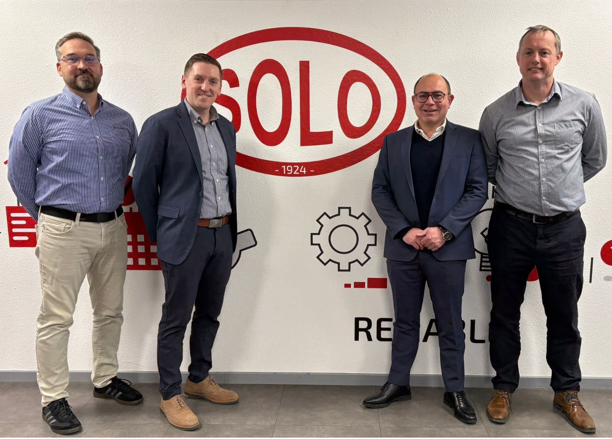
1. Gasbarre Thermal Processing Systems announced an exclusive licensing agreement with SOLO Swiss SA to bring Profitherm® modular bell furnace quenching systems to the North American market, giving Gasbarre rights to manufacture, promote, and sell the technology locally. This expansion enhances Gasbarre’s equipment portfolio and offers heat treat operations — from commercial shops to captive facilities serving aerospace, defense, and industrial sectors — a flexible alternative to traditional quench furnaces that can reduce infrastructure needs and improve processing efficiency.
2. IperionX has received a prototype order from American Rheinmetall to manufacture about 700 lightweight titanium components for U.S. Army heavy ground combat systems, using its patented recycled titanium technologies. This order supports U.S. defense efforts to reshore critical materials supply chains and could improve vehicle performance with significantly lighter parts, signaling growing demand for domestic, advanced titanium production in military manufacturing.
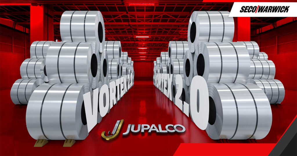
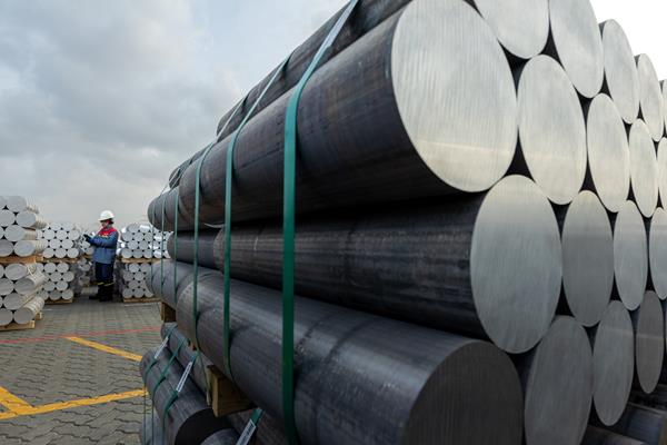
3. Jupiter Aluminum Industries (JUPALCO) has ordered two additional patented Vortex 2.0 aluminum coil annealing furnaces from SECO/WARWICK. The installation will expand JUPALCO’s heat treatment capacity while improving process efficiency and temperature uniformity. The project reflects continued investment in modern annealing technology to support growing aluminum processing needs.
4. Century Aluminum Company has emphasized that Emirates Global Aluminum‘s next-generation EX smelting technology will be critical to the development of its new primary aluminum smelter, one of the most advanced technologies deployed in the U.S. This platform is designed to improve productivity, reduce energy consumption per ton, and lower emissions, reinforcing both economic competitiveness and environmental performance in primary aluminum manufacturing.
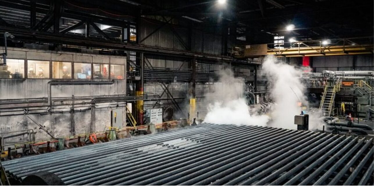
5. Global pipe manufacturer Tenaris has reactivated quenching and tempering operations at its Koppel, Pennsylvania facility, restoring a critical stage of in-house heat treating capacity that supports domestic oil country tubular goods (OCTG) production for the U.S. energy sector. The restart reinforces supply chain reliability for clients requiring high-performance steel pipe.
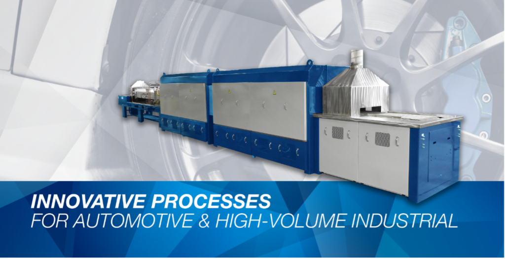
6. A Midwest automotive manufacturer is boosting its stainless steel brazing capacity by installing a new four-zone, 24-inch controlled-atmosphere brazing furnace from Gasbarre Thermal Processing Systems. The furnace will support higher production of critical automotive components.
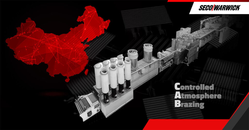
7. A Chinese thermal management manufacturer has significantly increased its production capacity by installing a new continuous controlled-atmosphere brazing (CAB) line supplied by SECO/WARWICK to support higher output of advanced cooling components for data centers, EVs, aviation, photovoltaics, and rail transport.
Company & Personnel
8. Spectrum Thermal Processing, a Cranston, Rhode Island heat treat provider, was acquired by global specialist processor Bodycote plc and integrated into its Aerospace, Defence & Energy division in a deal that closed January 14, 2026. This move brings Spectrum’s Nadcap-accredited vacuum heat treatment, low-pressure carburizing, and gas nitriding capabilities into Bodycote’s U.S. network, expanding regional capacity and improving lead times and supply-chain resilience for aerospace and defense component manufacturers.
9. A Tier 1 automotive supplier ensured uninterrupted production during a planned maintenance shutdown by tapping outsourced burst heat treating capacity from Bluewater Thermal Solutions’ St. Mary’s, Pennsylvania facility, rapidly scaling to meet strict OEM requirements. This collaboration kept deliveries on schedule and highlights the growing importance of flexible heat treating resources in supporting automotive supply-chain resilience.
10. Atlantic Fire Brick & Supply, a company that provides refractory products and installation services for furnaces, kilns, and other high-termperature equipment, has been acquired by Plibrico Company LLC in a move that expands refractory distribution and service capabilities for industrial thermal processing operations across the southeastern United States.
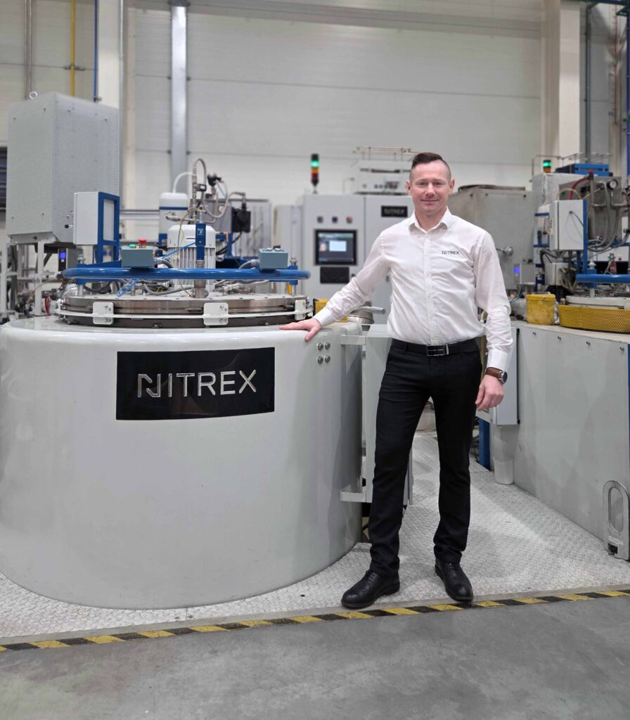
11. The AICHELIN Group has appointed Robert Sokoliński as CEO and general manager of Nitrex Metal Sp. z o. o. in Poland, effective January 1, 2026, tasking him with leading the subsidiary strategic and operational development within the group. The leadership move reinforces AICHELIN’s commitment to expanding advanced thermochemical heat treating capabilities in Europe, supporting automotive and industrial manufacturers with reliable, high-performance surface treatment solutions.
12. Bodycote’s Derby and Rotherham heat treat facilities now operate with zero direct carbon emissions, having transitioned to fully electric operations powered by 100% renewable energy — a milestone in decarbonization trends in thermal processing. This achievement signals growing momentum towards sustainable practices in the aerospace and automotive supply chains, helping clients meet ambitious carbon-reduction targets while maintaining process performance.
13. NUTEC Group Chairman Genaro Cueva and CEO Daniel Llaguno have appointed long-time executive Rodrigo González as president of NUTEC Bickley, following his 24-year tenure in senior engineering and operations roles. Llaguno praised González’s capabilities and alignment with NUTEC’s values, expressing confidence that he will successfully lead the company into the future while strengthening its position in the industrial heating sector across North America.
14. Thermcraft Inc. announced that Thermo Kinetics has joined as its authorized distributor for Canada, expanding Thermcraft’s reach for its thermal processing and industrial heating equipment across the Canadian market. This partnership brings together Thermcraft’s furnace and thermal solutions expertise with Thermo Kinetics’ local sales and technical support capabilities, strengthening service and market impact in the region’s industrial heating sector.
15. TFL Incorporated, a Houston-based provider of refractory materials and precast shapes, has been acquired by Plibrico Company LLC in a move that strengthens resources and technical support for high-temperature industries. The acquisition enhances service capacity and product availability for clients operating in demanding thermal-processing environments, including sectors that rely on consistent refractory performance to maintain uptime and efficiency.
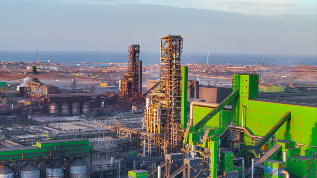
16. Tosyalı Algérie, working with technology partner Midrex, set a new world production record for direct reduced iron (DRI), marking a major milestone in large-scale, low-carbon ironmaking. The achievement underscores growing momentum around DRI as a critical feedstock for steel producers seeking greater efficiency and reduced emissions. For the broader metals industry, it signals continued investment and confidence in DRI technology as a foundation for future steel and downstream thermal processing supply chains.
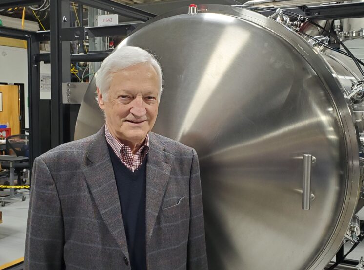
17. Claus Joens, founder of Elnik Systems, has retired after decades of advancing debind-and-sinter furnace technology. His leadership helped strengthen metal manufacturing capabilities critical to defense and advanced industrial applications, leaving a lasting mark on the MIM and thermal processing industries.
18. The Industrial Heating Equipment Association (IHEA) has announced its 2026-2027 Board of Directors and Executive Officers, naming Jason Safarz of DUNGS Combustion Controls as president, Bob Fincken of Super Systems, Inc. as vice president, and Chad Spore of John Deere as treasurer. IHEA leadership highlighted Spore’s appointment as a historic milestone, marking the first end-user officer in nearly a century and reinforcing alignment between equipment suppliers and industrial end users.


Kudos
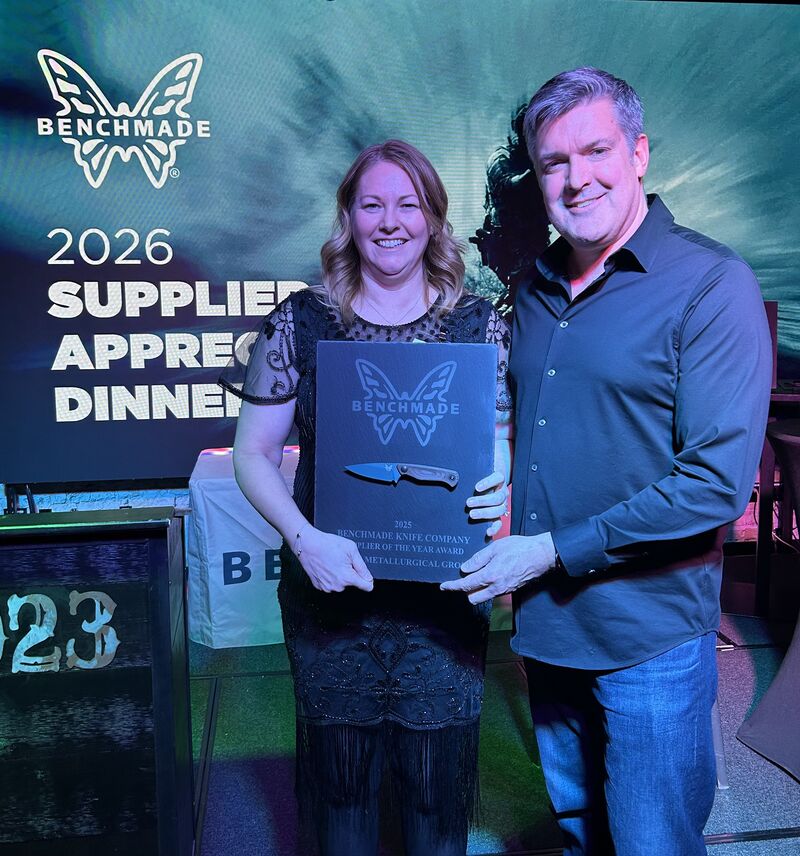
19. Stack Metallurgical Group was honored as a Supplier of the Year by BENCHMADE Knives at the 2026 SHOT Show Supplier Showcase. This recognition at one of the shooting, hunting, and outdoor industry’s largest trade events underscores Stack’s growing influence and excellence in precision metal processing and heat treat services within the manufacturing supply chain.
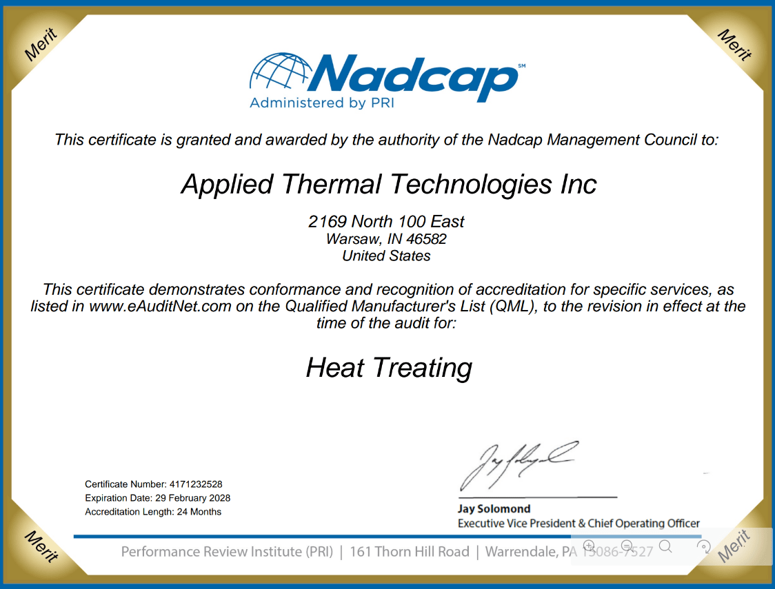
20. Applied Thermal Technologies Inc. received its 4th consecutive 24-month merit for Nadcap.
21. Vacu Braze announced that its metallurgical laboratory has achieved Nadcap accreditation.

21 News Chatter to Keep You Current Read More »