Sigma Phase Metallurgy 101
In this Technical Tuesday installment, Nick Hicks, metallurgical services manager at Rolled Alloys, emphasizes the importance of mastering the basics of sigma phase metallography in stainless steels. Understanding these fundamentals helps you know when to consult a metallurgist and guarantee top performance of heat treated parts.
This informative piece was first released in Heat Treat Today’s November 2025 Annual Vacuum Heat Treating print edition.
Heat treaters are always seeking new methods of heat treat and new alloys to improve performance at a lower cost. In the world of stainless steel, there are well-known choices like 310 and newer options like RA 253 MA®. These alloys have exceptional qualities, especially RA 253 MA, which has creep strength up to 2000°F and oxidation resistance up to 2000°F. However, heat treaters should be aware of a potential issue when using such alloys: the formation of sigma phase over time.
In some cases, premature wear in nickel alloys was attributed to sigma phase embrittlement, but it’s important to note that sigma phase does not actually precipitate in nickel alloys. Instead, the actual microstructure may exhibit grain boundary oxidation or carbides. This article seeks to provide a clearer understanding of sigma phase metallography and its impact on stainless steels.
Definition of Sigma Phase
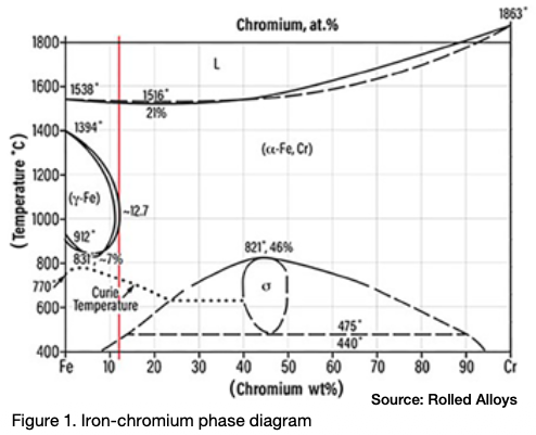
Sigma phase is an intermetallic compound made up of chromium and iron. It is hard, brittle, and non-magnetic. At room temperature, the presence of sigma phase can make the material so brittle that a sudden, hard impact can shatter a piece of metal that contains it, similar to a piece of glass. Pure sigma phase forms when the chromium content is between 42% and 50%, and it is one of the equilibrium phases in the iron-chromium phase diagram as seen in Figure 1.
The peak temperature for sigma phase formation in a 46% Cr alloy is 1510°F. A literature review reveals that different sources cite varying temperature ranges for sigma phase formation. This variation is due to each alloy having its own unique sigma formation range. According to one expert (Kelly 2005), sigma phase can form in the temperature range of 1100°F–1600°F (590°C–870°C).
Metallurgy of Sigma Phase
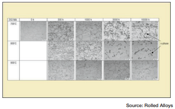
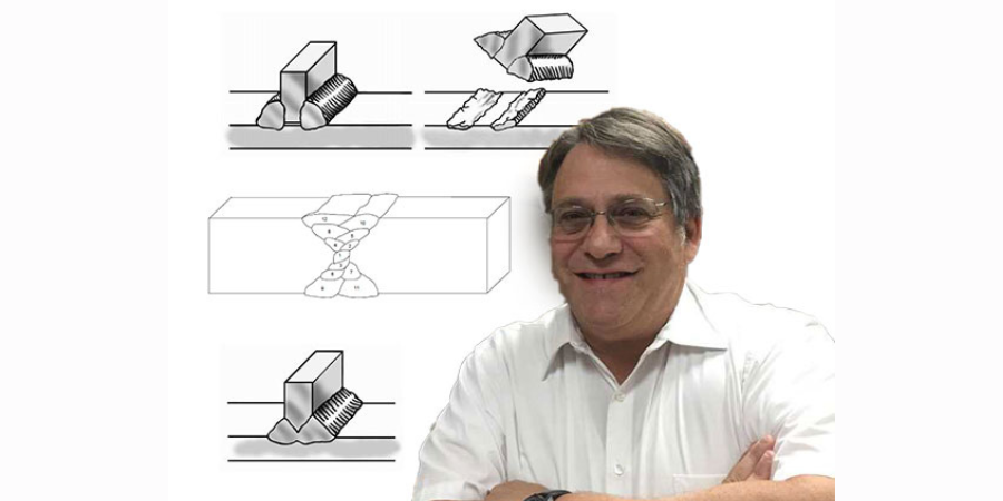
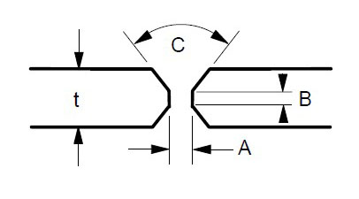
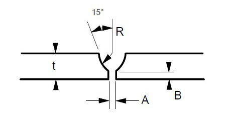
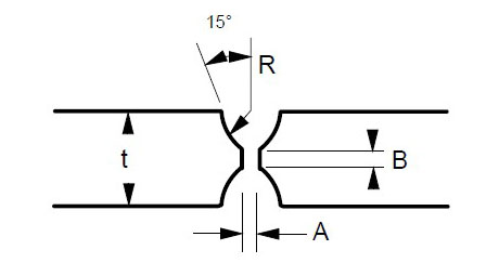
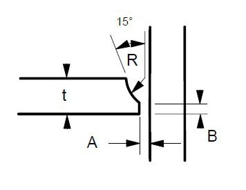
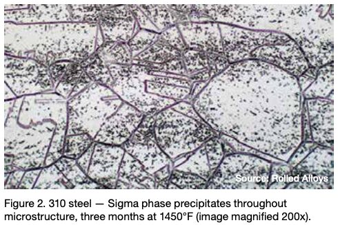
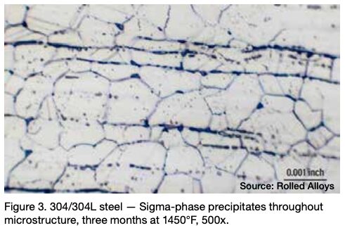
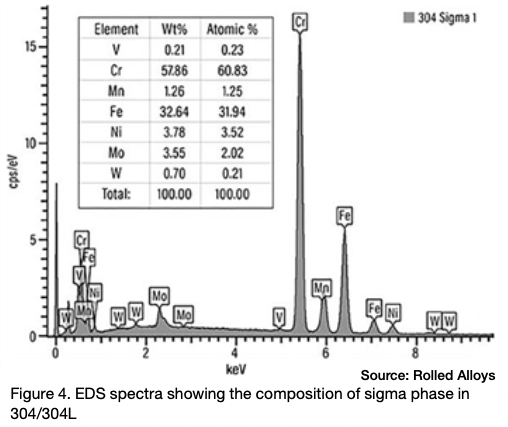
Many engineers require assistance in distinguishing between sigma phase and the formation of grain boundary oxides and carbides. Otherwise, they might reach incorrect conclusions. Sigma phase is a precipitation product that can manifest in both individual grains and along grain boundaries. Examples of sigma phase formation can be observed in Figures 2–4.
When observing nickel and certain nickel alloys like RA330®, confusion can arise due to the presence of grain boundary oxidation or carbide formation. These occurrences are often mistaken for sigma phase formation by engineers, but it’s important to note that a nominal nickel content of at least 35% is sufficient to prevent sigma phase formation.
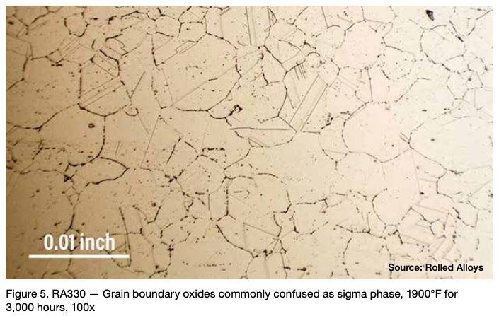
Figure 5 depicts RA330 after a 3,000-hour duration at 1900°F. Despite 1900°F being significantly higher than the sigma formation range, some engineers determined that the grain boundary oxides were sigma phase. When there is any uncertainty, it is advisable to consult with a metallurgist who is knowledgeable about the metallography of these alloys.
Physical Properties of Material with and without Sigma Phase
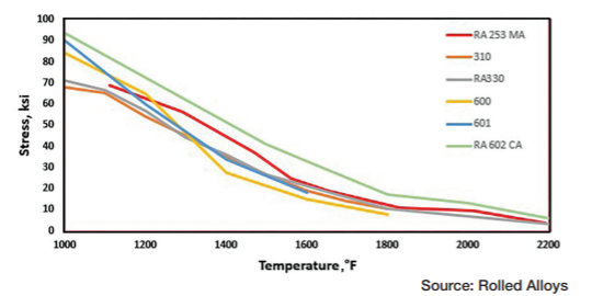
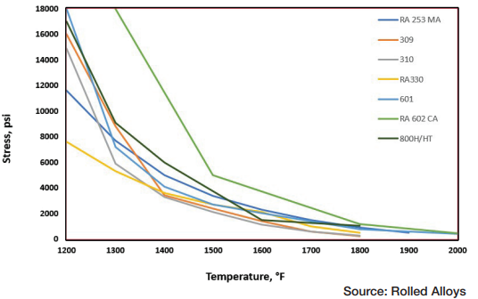
Table A displays the results of impact testing for six different alloys aged at three different temperatures for varying durations. All the alloys experienced some degree of deterioration over time, with certain alloys showing significant losses and reduced ductility. Further analysis revealed that each alloy has its own specific temperature at which sigma phase formation occurs most rapidly. In fact, the formation of sigma phase is dependent on the time at temperature, which makes a C-type curve.
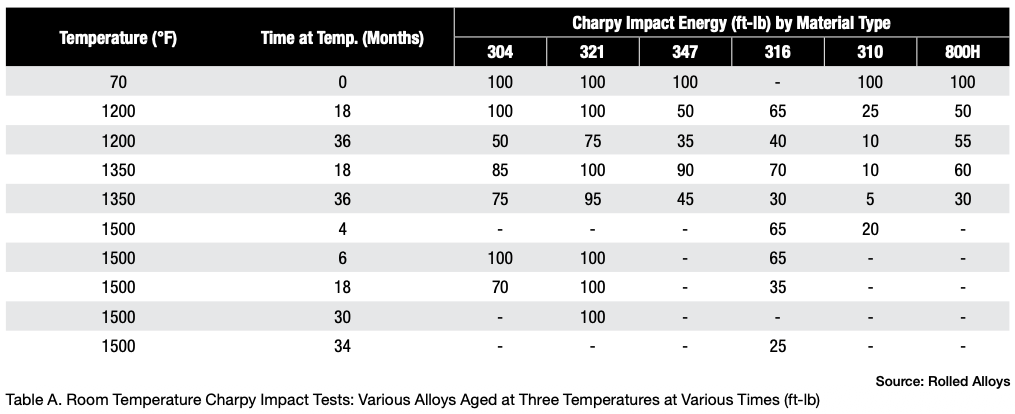
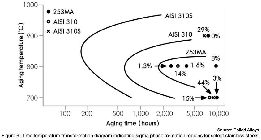
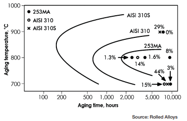
Figure 6 depicts the time temperature transformation curves for sigma phase formation for a few different stainless steels. Any point past a specific alloy’s curve results in the formation of sigma phase.
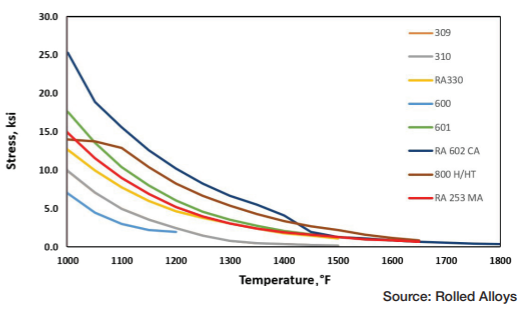
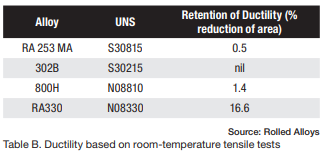
The results of elevated temperature impact testing for six alloys are presented in Table B. Many of the values in the table indicate that these alloys generally show either no loss of ductility or significantly less loss of ductility when the testing is carried out at elevated temperatures. In most cases, the materials still exhibit sufficient ductility to be safely used at these temperatures.
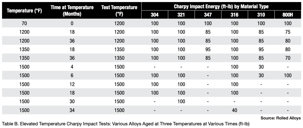
When these alloys have formed sigma phase and then cooled to room temperature, it’s important to prevent any kind of impact. At operating or heat treating temperatures, these alloys generally maintain enough ductility to be safely used.
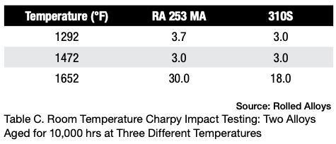
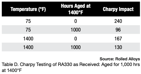
Table D displays the results of Charpy testing conducted on RA330 after aging. Although there is a slight decrease in ductility, the material still exhibits sufficient energy absorption to be considered quite ductile and safe for use at room temperature.
Conclusion
Sigma phase precipitation is a phenomenon that occurs in stainless steels and alloys containing less than 35% nominal nickel content. This does not occur in nickel alloys with 35% nickel or more. Sigma phase can make materials very brittle at room temperature. However, at elevated temperatures within typical heat treating ranges, most materials retain sufficient toughness to be used without any concern. It’s important to note that even at high temperatures, toughness is lost. More caution should be exercised in choosing alloys for vibrating systems, as constant vibration can cause premature failure if sigma phase has formed.
Engineers may mistakenly identify grain boundary oxidation or carbides as sigma phase formation in alloys that do not actually form sigma phase. To ensure accurate conclusions, it is important to have interpretations verified by experienced metallurgists who are familiar with the metallography of stainless steels and nickel alloys.
An understanding of the basics of sigma phase metallurgy in stainless steels will help the heat treater, manufacturer, and end user avoid failures associated with sigma phase embrittlement.
References
Andersson, Thomas, and Thomas Odelstam. 1984. Sandvik 253MA (UNS S30815) – The Problem Solver for High Temperature Applications. Sandviken, Sweden: R&D Centre AB Sandvik Steel Bulletin, October.
ASM International. 1986. Binary Phase Diagrams. Metals Park, OH: ASM International.
Crucible Inc., Materials Research Center. 1972. Private Communications, January 10 and June 22.
Herring, Daniel H. 2012. “Sigma Phase Embrittlement.” Industrial Heating. Troy, MI: BNP Media, March.
Kelly, James. 2005. Heat Resistant Alloys. Rolled Alloys. https://www.scribd.com/document/90619472/HeatResistantAlloys-RolledAlloys.
Lien, George E. 1968. Behavior of Superheater Alloys in High Temperature, High Pressure Steam. New York, NY: The American Society of Mechanical Engineers.
Rolled Alloys. n.d. Internal Reports. Temperance, MI.
Rolled Alloys. n.d. Rolled Alloys Bulletin 1353: RA 353 MA® Alloy. Temperance, MI.
About The Author:

Metallurgical Services Manager
Rolled Alloys
Nick Hicks is the metallurgical services manager at Rolled Alloys. He holds a bachelor’s degree in mechanical engineering from the University of Toledo and a master’s degree in materials science from Worcester Polytechnic Institute. Nick represents Rolled Alloys at organizations such as the Materials Technology Institute (MTI) and the American Society for Testing and Materials (ASTM). He is also a former Emerging Professional on the ASM Heat Treat Board. Nick specializes in stainless steel and nickel alloy metallurgy for high-temperature and corrosion-resistant applications.
For more information: Contact Nick at nhicks@rolledalloys.com.
This article was initially published in Industrial Heating. All content here presented is original from the author.

Sigma Phase Metallurgy 101 Read More »