


NFPA 86

Answers in the Atmosphere: Hydrogen Part 1 — Powerful Reducing Properties, High Thermal Conductivity

In this installment of Answers in the Atmosphere, David (Dave) Wolff, an independent expert focusing on industrial atmospheres for heat treat applications, examines the powerful reducing properties and high thermal conductivity that make hydrogen a critical atmosphere in metal thermal processing.

This informative piece on hydrogen’s role in sintering, annealing, and surface protection — including how it is sourced, how it behaves inside the furnace, and how operations can safely manage this flammable atmosphere under NFPA 86 — was first released in Heat Treat Today’s April 2026 Annual Induction Heating & Melting print edition.


Hydrogen is widely used in metal thermal processing for sintering of powdered metal fabrication technologies and for heat treatment (e.g., annealing, brazing) of bulk metal manufactured components. This column draws heavily from an interview the author had with Stephen Feldbauer Ph.D., director of Research & Development at Abbott Furnace. Abbott Furnace is a leading furnace manufacturer for continuous furnaces and furnace controls. As R&D Director, Steve leads Abbott’s work in pioneering furnace advances with a special focus on debinding and sintering.

Why Hydrogen?

Stephen Feldbauer, PhD
Director of Research & Development
Abbott Furnace

Hydrogen provides two desirable characteristics to heat treaters: very high chemical reducing potential and the highest thermal conductivity of any gas. The high reducing potential enables hydrogen to convert heated metal oxide coatings to pure metals. This is extremely helpful for successful sintering of powder metallurgical parts. Superior thermal conductivity enables rapid part heat up and cool down. Compared with either vacuum or inert gas atmospheres, hydrogen enables much faster throughput and achieves shorter furnace cycles.

Hydrogen-containing atmospheres are required to successfully sinter most iron-based metal parts, whether manufactured by powder metallurgy (PM), metal injection molding (MIM), or binder-jet metal additive manufacturing techniques. As-received, the iron-containing metal powders used for these advanced fabrication techniques are covered with an iron-oxide coating, making it virtually impossible to successfully sinter the particles together under reasonable temperature conditions. Reducing the oxide coating enables successful sintering.

Hydrogen-based atmospheres used with a tube or strand furnace are the primary surface protective technology used for drawn components (e.g., wire, tubing, and profiles). Hydrogen simultaneously protects the part surface from oxidation and allows metal to anneal, which softens it and restores toughness after it has been hardened by the drawing process.

Sourcing Hydrogen

Because of its high reactivity, hydrogen is almost never found in nature as a pure gas (H2). Instead, it is generally found as a component in a compound like water (H2O) or a hydrocarbon gas or liquid, such as methane (CH4), propane (C3H8), or longer hydrocarbon. In order to be used as a thermal processing atmosphere, hydrogen is liberated from these hydrogen-containing compounds to exist as a pure gas while in use in the hot furnace.

The liberation of elemental hydrogen from its compound carrier can happen at a remote plant operated by an industrial gas company provider, in which case the hydrogen would be compressed or liquified for delivery to the thermal treatment client, or may be conducted at the site of the thermal processor themselves through use of on-site generation equipment. User choices of approaches to pure hydrogen supply will be covered in future columns.

Inside the Furnace

Inside the hot furnace, hydrogen changes metal oxide coatings to pure metals by preferentially reacting with the metal oxides to produce pure metal and water vapor. Thus, the furnace atmosphere dewpoint (a measure of gaseous water content) will increase as the hydrogen simultaneously creates pure metal surfaces and produces water vapor as a byproduct. The water vapor is swept out of the furnace and replaced by the clean furnace atmosphere that flows counter current to the heated metal product. Furnace atmosphere controls for hydrogen-based atmospheres use dewpoint as a key operating parameter.

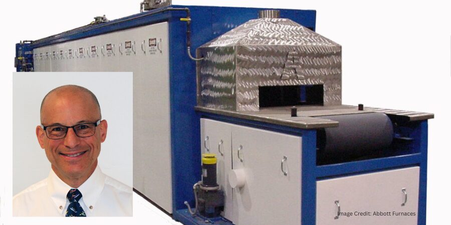
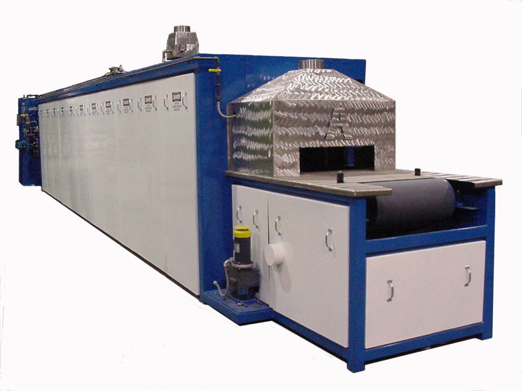
Hydrogen’s ability to protect the part surface from oxidation is critical in the annealing process. | Image Credit: Abbott Furnace

Since furnaces must open to admit parts for thermal processing, the furnace, the atmosphere system, and the procedures must all be designed to prevent unsafe conditions caused by hydrogen leaking out of the furnace, or air leaking in. Furnaces intended for a flammable gas atmosphere use doors, curtains, and pilot lights (i.e., flame curtains) to prevent hydrogen or other flammable gas from leaving the furnace without being combusted. These precautions avoid explosions inside or outside the furnace.

Furnaces for hydrogen-containing atmospheres utilize unique design and construction approaches to safely use this flammable atmosphere. In the U.S., furnace design and operation is guided by NFPA 86, the furnace code. NFPA 86 defines certain furnace design features and also defines standard operating techniques for safe operation with a combustible atmosphere, such as a hydrogen-containing atmosphere. Similar codes and standards are used in other countries.

Next month, this column will pick up the question of cost by looking at options for generation of hydrogen atmosphere blends. Generation of pure hydrogen will be a future topic.

About The Author:

David (Dave) Wolff
Industrial Gas Professional
Wolff Engineering

Dave Wolff has over 40 years of project engineering, industrial gas generation and application engineering, marketing, and sales experience. Dave holds a degree in engineering science from Dartmouth College. Currently, he consults in the areas of industrial gas and chemical new product development and commercial introduction, as well as market development and selling practices.

For more information: Contact Dave Wolff at Wolff-eng@icloud.com.

Answers in the Atmosphere: Hydrogen Part 1 — Powerful Reducing Properties, High Thermal Conductivity Read More »

Understanding 2 Recent NFPA 86 Updates for Metal Processors

Is your combustion equipment truly compliant? In this guest column, Mesa Wentling, Marketing/Field Service at PSNERGY, explores two mandatory annual requirements introduced in the latest edition of NFPA 86: Standard for Ovens and Furnaces. The updates — Safety Train Verification and Radiant Tube Integrity Inspections — directly affects combustion-based heat treating equipment. Wentling breaks down what each requirement entails, how to achieve compliance, and the risks operators face if they don’t.


NFPA 86: Standard for Ovens and Furnaces establishes the minimum safety requirements for equipment that uses heat to process materials. The standard is designed to prevent fires, explosions, and hazardous operating conditions in industrial heating systems.

Although there are many updates in the most recent edition, these two mandatory annual requirements directly affect combustion equipment in use by most heat treating operations: Safety Train Verifications and Radiant Tube Integrity Inspections.

Safety Train Verification

The annual Safety Train Verification requirement focuses on confirming that each component of the fuel safety train is present and functioning correctly. Often in older furnace installations, components like gas line drip legs or wye strainers were omitted. Combustion systems rely on a sequence of valves, switches, regulators, and interlocks that must function in a precise way for safe furnace operation. These devices can drift out of adjustment, wear mechanically, or fail electrically over time.

Verifying the gas safety train annually ensures that all protective devices respond when necessary. This procedure confirms valve functionality, switch setpoints, regulator performance, and the integrity of wiring and interlocks. The goal is to identify any signs of degradation of the gas safety train before it becomes a safety hazard.

Radiant Tube Integrity Inspections

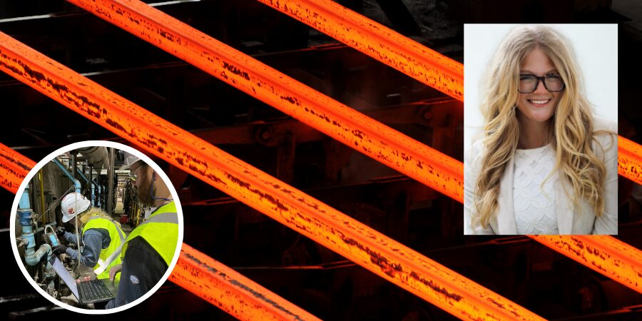
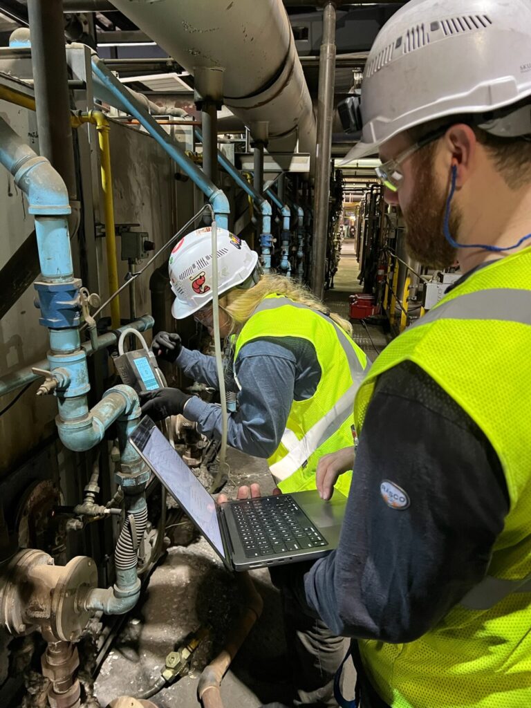
RTI Inspection | Image Credit: PSNERGY

Radiant Tube Integrity Inspections are now another required annual check. Radiant tubes operate in severe thermal environments that can lead to cracking, oxidation, warping, or weld deterioration. A tube that loses integrity can leak products of combustion into the furnace chamber, which can contaminate products, affect temperature uniformity, and create unsafe operating conditions. Loss of integrity can occur through thermal cycling, corrosion, or mechanical stress. The annual inspection ensures that any failing tubes are identified before they compromise safety or performance.

Three common ways to perform Radiant Tube inspections are with (a) digital combustion technology, (b) pressure testing, and (c) visual inspection. Digital combustion technology uses furnace atmosphere and O₂ data to identify failing tubes. This method significantly reduces downtime and manpower, improves safety, and increases accuracy. Pressure testing includes furnace shutdown, tube sealing and pressurization, pressure verification, and final seal removal and reassembly. Visual inspection requires furnace shutdown and multi-day cooling, confined space entry with elevated risk, and offers limited accuracy due to restricted access, typically identifying only major cracks in cold tubes.

Noncompliance Is a Liability

It has been observed through industry interactions that many heat treaters have not yet come into compliance with these updated NFPA 86 requirements because of the long-standing belief that their equipment was effectively grandfathered in. Historically, older furnaces and ovens were not always required to meet new verification or inspection criteria. That is no longer true. Due to the grandfather clause being eliminated, every furnace or oven, regardless of installation date, must comply with the current standard.

Failure to comply with the annual requirements can have significant consequences. Noncompliance increases exposure to safety incidents, unplanned outages, and equipment damage. Insurance carriers and auditors are placing greater emphasis on documented conformance to NFPA 86, and missing these verifications can affect coverage or lead to corrective actions.

In the event of an incident, lack of compliance presents substantial liability. Connect with industry experts in combustion like PSNERGY who can provide resources that help heat treaters and metal processors meet these requirements efficiently. You should expect detailed guidance, inspection procedures, and combustion technology for Safety Train Verifications and Radiant Tube Integrity Inspections, along with service options for facilities that need support. These resources assist operators in building compliant, safe, and reliable operations. For more information on the recent edition of NFPA 86, be sure to visit www.nfpa.org.

About The Author:

Mesa Wentling
Marketing/Field Service
PSNERGY

Mesa Wentling specializes in industrial marketing, with hands-on experience supporting furnace efficiency, combustion, and manufacturing-focused initiatives. She works with engineers and furnace specialists to help communicate complex combustion and performance data in a clear, accessible way.

For more information: Contact Mesa Wentling at mwentling@psnergy.com or LinkedIn.

Understanding 2 Recent NFPA 86 Updates for Metal Processors Read More »

What Have You Learned from the Combustion Corner? Part 2

OCSince February 2021, Heat Treat Today has had the privilege of publishing the Combustion Corner. In each of these columns, John Clarke, technical director at Helios Electric Corporation, shares his expertise on all things combustion. In this Technical Tuesday, we're taking a moment to review more of the key points from John's columns. As always, we hope this review helps you to be more well informed, and to make better decisions and be happier. Enjoy these five summaries of the second half of the Combustion Corner columns. To view each installment, click the blue heading below. 


How To Lower the Cost of Operating Your Burner System

Process consistency and energy savings are inextricably linked. To lower operating costs and increase process consistency, John Clarke suggests asking three questions: What temperature is my furnace or oven, really? Do I have excessive safety factors built into my process to compensate for not knowing the temperature at the core of the part being heat treated? How much fuel can I save with a shorter cycle?

Are You Holding on to Uncashed Checks?

Contact us with your Reader Feedback!

Reducing natural gas consumption is not the only way heat treaters can save money. Verifying internal furnace pressure, rebuilding door jams, and taking the time to consider if excess air is reducing combustion efficiency are all as good as cashing a check. Maintaining a consistently uniform furnace temperature saves more money than the energy conserved from using less fuel.

"To not invest money on worthwhile projects makes as much sense as not depositing your paycheck."

The "Known – Unknown": Preparing Your Facility for Unpredictable World Events

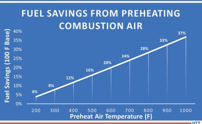
The biggest question mark in a heat treater’s mind is often, “What will natural gas prices be in the future?” Since we cannot know the answer to that question, what are some things heat treaters can do to prepare for unpredictable natural gas prices? Burner recuperation, using the waste heating exiting the furnace to preheat combustion air, is a tried-and-true method for reducing consumption. Before trying burner recuperation, the following questions need to be asked: How much will it cost? How much can be saved? Can the existing furnace accept the higher flame temperatures?

Natural Gas Revisited

In this installment of the Combustion Corner, John Clarke takes some time to reassure the heat treating industry of two key facts about the United States' natural gas market:

  1.  40% of the electricity in the U.S. is generated using natural gas.
  2.  U.S production of natural gas was at al all-time high in 2021 and is rising. The U.S. is the largest producer of natural gas in the world.

With these two facts in mind, John postulates that the U.S. can be sure of a reliable supply of natural gas in the future, but, given the price differential between European and U.S. markets, American heat treaters are likely to see an increase in price per mmBTU.

How To Make $17,792.00 in a Couple of Hours

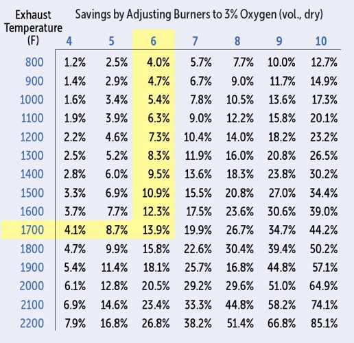
Saving money is the same as making money. Adjusting the oxygen levels of flue products measured with a handheld combustion analyzer to operate at an optimal percentage may yield more savings than you think. Reducing a non-recuperated burner from 6% oxygen to 3% oxygen garners $17,792 extra a year for the heat treater. A quick solution with a hefty payback rate.


Find heat treating products and services when you search on Heat Treat Buyers Guide.com


What Have You Learned from the Combustion Corner? Part 2 Read More »

What Have You Learned from the Combustion Corner? Part 1

OCSince February 2021, Heat Treat Today has had the privilege of publishing the Combustion Corner. In each of these columns, John Clarke, technical director at Helios Electric Corporation, shares his expertise on all things combustion. In this Technical Tuesday, we're taking a moment to review some of the key points from John's columns. As always, we hope this review helps you to be more well informed, and to make better decisions and be happier. Enjoy these seven summaries of the first half of the Combustion Corner columns. To view each installment, click the blue heading below. 


Natural Gas 101

In his inaugural column with us, John Clarke sets up the Combustion Corner column series with a look at the basics of natural gas. What do heat treaters need to know about natural gas supply and demand, availability, pricing, and consumption. Plus, the risks heat treaters should consider when making decisions about maintenance and equipment acquisition.


Excess Air: Its Role in Combustion and Heat Transfer

Contact us with your Reader Feedback!

Excess air is the percent of total air supplied that is more than what is required for stoichiometric or perfect combustion. In heat treating systems, excess air plays many roles, both positive and negative. The perfect mixture of oxygen and gas can be elusive. When it comes to saving money and improving safety, carefully monitoring excess air in fuel-fired systems pays dividends.


Moving Beyond Combustion Safety

Maintain regular inspection and maintenance schedules

Combustion safety is the number one priority for all heat treaters. But, what factors should be considered when all safety considerations are in place? After all, many fire protection standards are designed to protect life and property (as they should be), but not the bottom line. The next priorities for heat treaters are: reduce burner failure and therefore reduce downtime, consider component failure rates when designing or purchasing a system, and maintain regular inspection and maintenance schedules.

Moving Beyond Combustion Safety — Plan the Fix

Downtime is costly. In order to prevent downtime, heat treaters need to “plan the fix” before the fix is necessary.

Planning the fix entails more than an annual inspection. One way to address shut-down-causing errors before they happen is to carefully examine gas pressure switches; switch contact ratings, location, pressure ratings, and protection of the switch from “bad actors” in the fuel gas are all things to consider.


Moving Beyond Combustion Safety — Designing a Crystal Ball

Rapid switch response

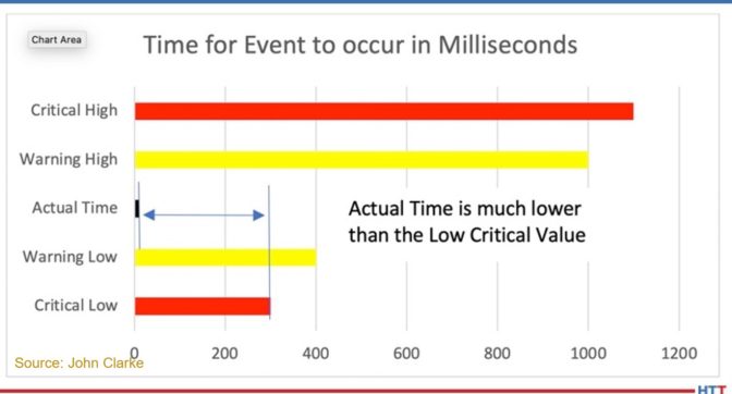
Pressure switches are either on or off. How can heat treaters use pressure switches to detect a possible failure before it occurs? The simple answer: the methods to analyzing time before shutdown is the heat treater’s crystal ball. Creating predetermined warning bands (time limits, which the pressure switch should not exceed or fall below) and monitoring switch response times within these predetermined times by PLC can give a glimpse into future shutdowns.


Nuts and Bolts of Combustion Systems — Safety Shutoff Valves

The NFPA allows for two arrangements of safety shutoff valves: the simple double block and the double block and vent. Both of these arrangements are appropriate as the last line of defense against a safety issue. How can heat treaters bring safety shutoff valves into compliance with NFPA 86? In this installment of the Combustion Corner, John Clarke clarifies how to comply with this common standard and lists some important considerations for choosing between a simple double block and a double block and vent arrangement.


Stop the Burn: 3 Tips to Cut Natural Gas Costs

In this column and the following columns in the series, John revisited the topic of natural gas. Reducing natural gas consumption is the best way to reduce cost. How can heat treaters do this? John suggests that we "optimize our processes, reduce unnecessary air, and contain heat within the furnace and/or capture the energy that leaves our system to preheat work or combustion air."


Find heat treating products and services when you search on Heat Treat Buyers Guide.com


What Have You Learned from the Combustion Corner? Part 1 Read More »

Nuts and Bolts of Combustion Systems – Safety Shutoff Valve

op-edSafety shutoff valves are the last line of defense against a potentially catastrophic incident. When conditions require, they interrupt the flow of fuel to the burner(s) and oven. There are many options when selecting fuel safety shutoff valves for your application. The construction and application of these devices is highly regulated by interlocking standards created by many different organizations. The goal of this article is to clarify how to comply with the most common standard affecting the reader: NFPA 86.

This column appeared in Heat Treat Today’s 2021 Trade Show September print editionJohn Clarke is the technical director at  Helios Electric Corporation and is writing about combustion related topics throughout 2021 for Heat Treat Today.


John B. Clarke
Technical Director
Helios Electric Corporation
Source: Helios Electric Corporation

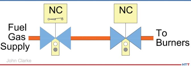
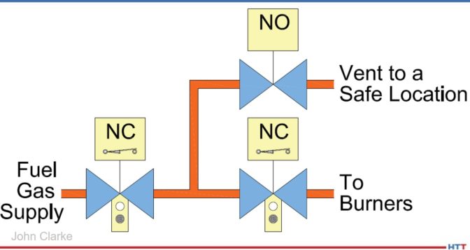
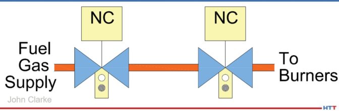
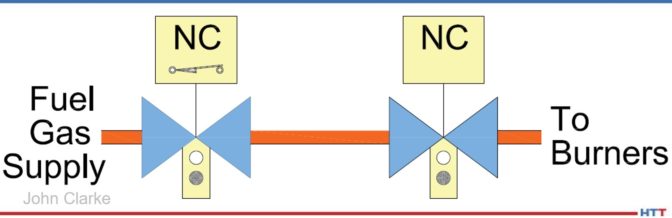
To start, we must define our terms. The 2019 edition of NFPA 86* defines a safety shutoff valve as a “normally closed valve installed in the piping that closes automatically to shut off the fuel, atmosphere gas, or oxygen in the event of abnormal conditions or during shutdown.”1 A valve is “normally closed” (NC) if it closes automatically when power is removed. A furnace or oven typically has as few as two or more safety shutoff valves. [Author’s note: If the system uses radiant tubes for heating, and all the criteria are met, it may be acceptable to use only one valve in series, but this exception is not recommended by the author and will not be covered in this article.] There are two common arrangements for safety shutoff valve arrays—the Simple Double Block (Illustration 1) and the Double Block and Vent (Illustration 2). While both arrangements are compliant with the current version of NFPA 86, the vent is NOT required. In other words, Illustration 1 and Illustration 2 below are both acceptable.

The simple double block arrangement consists of two automatic, normally closed (NC) valves piped in series. It provides redundancy—both valves must leak for fuel gas to pass to the burner system. A double block and vent has two automatic, NC valves piped in series with a third automatic normally open (NO) valve installed between the NC valves. The purpose of the NO valve is to provide a path for any fuel gas leaking past the first NC valve to move to a safe location. Whether one should deploy a double block and vent approach depends on several considerations: Is the NO valve supervised? Is the selected vent location safe? And how will the system be inspected?

Illustration 1

Illustration 2

To start with, if the NO vent valve’s coil or wiring fails, it will remain open even when the system is operating—venting fuel gas. This is not only expensive, but high concentrations of vented fuel gas are an environmental and safety hazard. The solution to this concern is installing a monitored vent valve that only opens the NC valves after the vent valve is proven to be closed. This is typically accomplished with a proof-of-closure position switch that only closes after the vent valve is fully closed.

The next concern is the location and maintenance of the vent. The vent must terminate at a safe location that can accept the entire flow of fuel gas in the event of a failure. Therefore, hazards such as fresh air intakes and sources of ignition must be avoided at all costs. It is also important to periodically inspect the vent piping to ensure it remains unobstructed—insects and rodents may find the vent line a comfortable place to nest and bring up their young.

The last challenge is the periodic inspection of the vent valve and the vent piping—it is generally a challenge to test whether a vent line meets the design criteria, and leaking fuel gas can be vented without excessive backpressure.

A simple double block provides redundancy without the complexity of the vent. Good design practice, with proper valve selection, combined with proper fuel filtration greatly improves the reliability and longevity of both systems.

Valves used for safety shutoff valve applications must be listed by an approval agency for the service intended.2 Furthermore, depending on the flow rate, the valves must be equipped with either a local indicator showing the valve position and a means to prove the valve is closed.

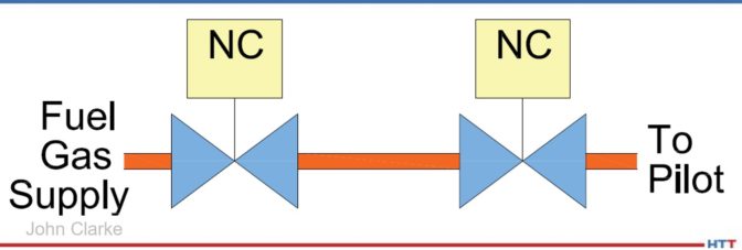
For fuel gas flows below or equal to 150,000 BTU/hour, two safety shutoff valves in series will suffice. See Illustration 3 below. This is very typical for pilot lines.

Illustration 3

For fuel gas flows greater than 150,000 BTU/hour and less than or equal to 400,000 BTU/hour, two safety shutoff valves in series with local position indication are required. Local indication is generally a window where an operator can see the actual position of the valve—open or closed—without relying on any electrical circuit or pilot light. See Illustration 4 below.

Illustration 4

For fuel gas flows greater than 400,000 BTU/hour, NFPA 86 requires two safety shutoff valves in series with local position indication. One valve must be equipped with a valve closed switch (VCS) that closes after the valve is fully closed, or a valve proving system (VPS) that runs a tightness check which must be utilized. The signal from either this VCS or VPS must be included in the burner management system’s (BMS) purge permissive string to ensure no fuel gas is flowing during the system preignition purge. The VCS must not actuate before the valve is fully closed. This is typically accomplished by using valve overtravel, where the valve closes first, then the mechanism continues to move until the VCS is actuated. This arrangement is depicted in Illustration 5 below.

Illustration 5

For the arrangement depicted in Illustration 5, NFPA only requires one valve be supervised with a VCS—the additional costs of supervising both valves are very low and will enhance safety.

Whatever the method used to shut off the fuel to burners or pilots, the array of valves must be inspected and tested annually or per the manufacturer’s recommendations, whichever period is the shortest. All systems must be designed to be tested—with provision provided to cycle valves in test mode and the ability to measure any potential leakage. We will explore how a fuel train should be “designed to be tested” in an upcoming article.

The one thing to always remember—safety shutoff valves are always deployed to provide redundancy, so that any one component failure will not prevent a safe interruption of fuel gas; but, as with all systems, there may be unforeseen events that can lead to complete failure. Only qualified people should design, operate, and maintain combustion systems.


References

[1] National Fire Protection Association – NFPA 86 Standard for Ovens and Furnaces 2019 Edition (NFPA, Quincy, Massachusetts, May 24, 2018) 3.3.82.2 pp 86-14.

[2] National Fire Protection Association – NFPA 86 Standard for Ovens and Furnaces 2019 Edition (NFPA, Quincy, Massachusetts, May 24, 2018) 13.5.11.1 pp 86-49.

About the Author:

John Clarke, with over 30 years in the heat processing area, is currently the technical director of Helios Electric Corporation. John’s work includes system efficiency analysis, burner design as well as burner management systems. John was a former president of the Industrial Heating Equipment Association and vice president at Maxon Corporation.

Nuts and Bolts of Combustion Systems – Safety Shutoff Valve Read More »