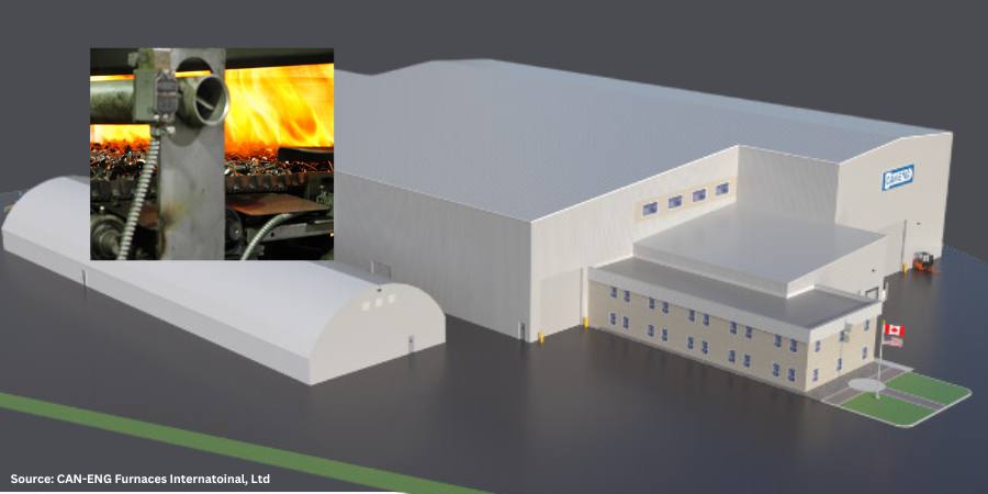
A North American furnace manufacturer recently announced plans to increase production capabilities by expanding its Ontario facility. The investment will consist of adding 45,000 square feet of modern manufacturing space as well as 18,000 square feet of office space. Construction is underway and is expected to be complete May of 2025.
CAN-ENG Furnaces International, Ltd., based in Niagara Falls, Ontario, CA, indicated the capacity expansion will be to their Plant #2 Operations in St. Catharines, Ontario. The manufacturing space will be outfitted with fabrication, assembly, and testing equipment to serve the changing needs of the industries they serve with thermal processing equipment, including stamping and fastener companies, electric vehicle and automotive component producers, the iron and steel industries, aluminum foundries, and agricultural, and construction manufacturers.
This expansion will double the current floor space and integrate enhanced overhead lifting capabilities to accommodate larger thermal processing systems being demanded by EV component and battery material processors. Upgrades include the addition of two 30-ton and two 20-ton overhead cranes to accompany the existing units presently in use. Future expansion plans that include foundation and utility upgrades have been considered during the design process.
The press release is available in its original form here.
IperionX, a U.S. titanium metal and critical materials company, recently delivered its first successful titanium furnace production run at the company’s Titanium Manufacturing Campus, based in Virginia. The furnace was installed in April 2024 with full run rate target capacity of at least 125 metric tons per year anticipated by the end of the year.
Anastasios (Taso) Arima CEO IperionX Source: IperionX
IperionX announced the commissioning of the Hydrogen Assisted Metallothermic Reduction (HAMRTM) furnace, noting that the titanium de-oxygenation production run represents a technological milestone for the company with a breakthrough +60x increase in titanium production capacity. The company’s titanium metal and critical minerals are processed for the consumer electronics, space, aerospace, defense, hydrogen, electric vehicles, and additive manufacturing industries.
“Over the last two years, we have successfully operated our pilot titanium production facility in Utah, producing high performance titanium products for customers and importantly – delivering first revenues for our company,” said Anastasios (Taso) Arima, CEO of IperionX.“Today, we demonstrated that our HAMR technology works at commercial scale. We successfully increased the furnace production capacity by ~60x times and produced high performance titanium that exceeds industry quality standards.”
The HAMR furnace is produced entirely from 100% scrap titanium (Ti-6Al-4V alloy, Grade 5 titanium), with a confirmed reduction in oxygen levels from 3.42% to below 0.07%, far exceeding the ASTM standard requirement of 0.2% for Grade 5 titanium. IperionX’s proprietary HAMR technologies offer a range of competitive advantages, including lower operating temperatures, reduced energy consumption, enhanced process efficiency, and accelerated production cycles.
The press release is available in its original form here.
An East Coast manufacturer has purchased six new vacuum sintering furnaces to replace the 1980s-era sintering furnaces it has used for heat treating components.
SECO/VACUUM received the commission to transition the production line from nine 40-yr-old SECO/WARWICK sintering furnaces to the six Vector sintering vacuum furnaces with 2-bar gas cooling. The furnace hot zones will be 26″ wide, 30″ high, and 62″ deep (660 x 760 x 1575 mm), which are the same size as the retiring furnaces, allowing them to continue using their existing heat treat fixtures.
Sintering is a critical process used to fuse metals together without reaching melting temperature. It is generally used for fixing the strands of wire mesh in place, consolidating powder metals, or any application where the objective is fusing metals together while remaining below melting temperatures.
The press release is available in its original form here.
The advent and increasing adoption of electric vehicles (EVs) has brought a wave of change to the automotive supply chain, including the heat treating industry. While the internal combustion engine (ICE) and all its related components may one day become a thing of the past, there are several key areas of every vehicle that aren’t going anywhere fast. In this Technical Tuesday article, Rob Simons, metallurgical engineering manager at Paulo, discusses the difference between EV and ICE vehicles and the latest heat treating trends to be aware of.
This informative piece was first released in Heat Treat Today’s August 2024 Automotive print edition.
ICE vs. EV Technology
The most apparent difference between EVs and ICE vehicles is that, with EVs, fuel and internal combustion engines are no longer needed. The two vehicle types rely on different sets of key components, and when it comes to making the cars run, EVs use fewer parts that require heat treatment.
Table 1. Existing ICE technology vs. EV technology
Without ICE systems, EVs require fewer fasteners, shafts, gears, and rods — all parts that are typically heat treated. But that doesn’t mean heat treatment is less critical for EVs. In fact, certain parts require additional attention on EVs when compared to ICE vehicles, and many safety-critical parts remain the same across both categories. Let’s begin our discussion with the differences in braking systems between the two technologies and what that means for heat treatment.
Latest Trends in Disc Brake Rotors
How EV Brake Systems Work
There’s no question that electric power innovations have completely revolutionized the way vehicles (and the automotive industry) operate. The regenerative braking system is just one aspect of this. Instead of relying on the conventional hydraulic system every time you press the brakes (which uses friction to decelerate), manufacturers have found a way to use the vehicle’s kinetic energy to put the electric motor into reverse, slowing down the vehicle and returning energy to the battery.
Although regenerative braking is more efficient, hydraulic braking still has one key advantage: stopping power. EVs today are equipped with conventional braking mechanisms for emergency purposes.
The Rust Conundrum
To address recurring rotor corrosion, heat treaters introduced ferritic nitrocarburizing (FNC). FNC is a thermal process traditionally used for case hardening, and for brake rotors, it’s used to achieve corrosion resistance.
The Solution: Corrosion-Resistant Rotors with FNC
To address recurring rotor corrosion, heat treaters introduced ferritic nitrocarburizing (FNC). FNC is a thermal process traditionally used for case hardening, and for brake rotors, it’s used to achieve corrosion resistance.
Figure 1 shows a perfect example of the difference that FNC makes. These are pictures of brake rotors from electric vehicles owned by two Paulo team members — one has brake rotors that were ferritic nitrocarburized and show no signs of rust, whereas the other did not go through the FNC process.
Figure 1a. EV brake rotor without FNC
Source: PauloFigure 1b. EV brake with FNC
Source: Paulo
Ferritic Nitrocarbonizing Process
FNC is a case hardening technique that uses heat, nitrogen, and carbon to toughen up the exterior of a steel part, improving its durability, decreasing the potential for corrosion, and enhancing its appearance. FNC is unique in that it offers case hardening without the need to heat metal parts into a phase change (it’s done between 975–1125°F). Within that temperature range, nitrogen atoms can diffuse into the steel, but the risk of distortion is decreased. Due to their shape and size, carbon atoms cannot diffuse into the part in this low-temperature process. However, carbon is necessary in the FNC process to generate desirable properties in the intermetallic layer.
Heat Treated Materials for Automotive Seating Components
Safety-Critical Components
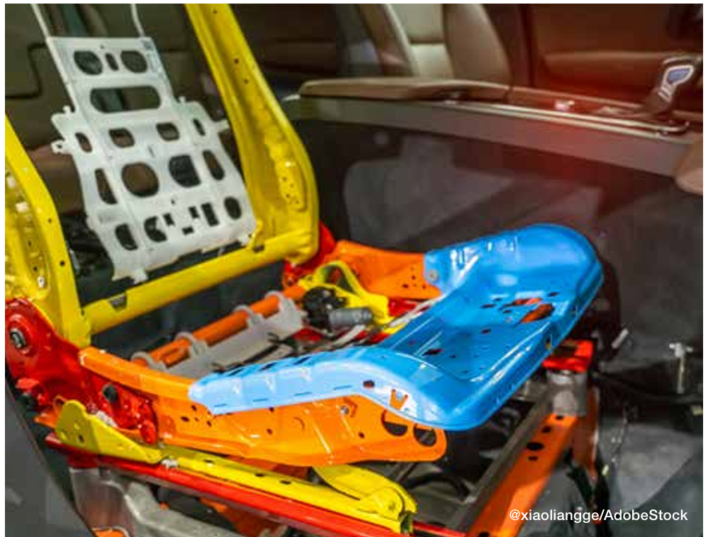
Like brake rotors, many automotive seating components (like mechanisms for seat recliners) are here to stay. Thermal processing is used to achieve stringent specifications that are put in place to keep drivers safe in the event of a collision. EV seat components and the thermal processes used to make them crash-ready are identical to those of ICE vehicle components.
Figure 2. To achieve the stringent specifications for components like seat recliners, identical
thermal processing is implemented for both EVs and ICE vehicles.
Seating Components
Generally, these components are case hardened (either carburized or carbonitrided), typically using one of the following materials:
1010 and 1020 carbon steel: These are plain carbon steel with 0.10% carbon content, fairly good formability, and relatively low strength.
1018 carbon steel: 1018 is a grade that’s often chosen for parts that require greater core hardness and better heat treatment response than 1010 or 1020.
10B21 boron steel: Boron steels are becoming more popular in the automotive industry due to their excellent heat treatment response.
4130 alloy steel and 8620 alloy steel: Alloy steels are more responsive to heat treatment than plain carbon steels, so the thermal processing specifications for parts made from these materials are often adjusted to account for the material’s innate strength properties.
Seat Belt Latches
High-strength seat belt latches are usually made from the following materials:
4140 and 4130 alloy steels: 4140 alloy steel is one of the most common engineering steels used in manufacturing. For seat latches and hooks, 4140 and 4130 will be neutral hardened to increase their strength and hardness throughout due to the high performance and precision required of these parts.
1050 carbon steel: 1050 is a medium carbon steel that contains 0.47–0.55% carbon content. Carbon steels are a less expensive choice when compared to alloy steels such as 4140 or 4130.
Seat Frames and Brackets
Seat frames (also known as seat brackets) give car seats their shape using slender pieces of steel joined together to form the skeleton of the seat. These components are often made from boron steels:
10B21 or 15B24 boron steel: These are a good choice for seat brackets because they are only marginally more expensive than other steels used in seating but have impressive toughness, have a good heat treat response, and are weldable.
A Closer Look: Case Hardening for Seating Components
Case hardening diffuses carbon or carbon and nitrogen into the surface of a metal from the atmosphere within a furnace at high temperatures. Adding carbon or carbon and nitrogen to the surface of steel hardens a metal object’s surface while allowing the metal deeper underneath to remain softer, creating a part that is hard and wear-resistant on the surface while retaining a degree of flexibility with a softer, more ductile core. This softness and ductility create toughness in parts, allowing them to respond to stress without failing. Case hardening is a general term for this heat treating method. Depending on the materials and specifications for the part, we apply various case hardening techniques, including carburizing and carbonitriding.
Figure 3. When it comes to heat treating, innovations are rarely exclusive to EVs.
Carbonitriding
During carbonitriding, parts are heated in a sealed chamber well into the austenitic range — around 1600°F — before nitrogen and carbon are added. Because the part is heated into the austenitic range, a phase change occurs, and carbon and nitrogen atoms can diffuse into the part. Carbonitriding is used to harden surfaces of parts made of relatively inexpensive and easily machined or formed steels, which we often see in automotive metal stampings. This process increases wear resistance, surface hardness, and fatigue strength. It is also good for parts that require retention of hardness at elevated temperatures.
Neutral Hardening
Also called through hardening, neutral hardening is a very old method for hardening steel. It involves heating the metal to a specified temperature and then quenching it, usually in oil, to achieve high hardness/strength. In this process, the primary concern is increasing hardness throughout the part, as opposed to generating specific properties between the surface and the core of the part.
All of the metal components of a seat belt, including seat belt loops, tongues, and buckles, are neutral hardened. Specifications typically dictate that these components are hardened to up to 200 thousand pounds per square inch (ksi).
Because seat belt components are visible to the end consumer, their cosmetics are important in addition to their mechanical properties. It’s important to keep the furnace free of soot and thoroughly clean the parts both before and after heat treatment. Proper cleaning readies the part for secondary processing, ensuring the success of activities like polishing and chrome plating.
The Convergence of EV and ICE Vehicles
To learn more about automotive heat treating, download the free Paulo Heat Treat Guide at paulo.com/AutoGuide.
The EV revolution has significantly transformed automotive manufacturing. Despite these changes, EV parts remain remarkably similar to those of their internal combustion engine (ICE) counterparts. Consequently, any advancements in materials or heat treating processes are swiftly adopted across the entire automotive sector. When it comes to heat treating, innovations are rarely exclusive to EVs.
About the Author:
Rob Simons Metallurgical Engineering Manager Paulo
Rob provides internal and external customer support on process design, material behavior, job development, reduction of variation, and physical analyses at Paulo. He holds a Bachelor of Science in Metallurgical Engineering from the Missouri University of Science & Technology (formerly known as the University of Mines and Metallurgy) and has worked at Paulo since 1987. Rob has analyzed several million hardness data points and/or process behaviors, leading him to develop many process innovations in the metallurgical field.
The Michigan expansion of a furnace manufacturer and heat treating company has advanced with the erection of the entire steel structure in one week. The new 20,000-sq-ft building for Solar Atmospheres of Michigan Inc. will not only house additional vacuum and air furnaces but will also serve as a new shipping and receiving space.
Solar Atmospheres, headquartered in Souderton, PA, relocated equipment to its Michigan facility in April, 2024, where the ten vacuum furnaces are fully operational. The expansion project, which began in July, 2024, will more than double the company’s current footprint in Chesterfield, MI, and is on track for completion by the end of 2024.
The press release is available in its original form here.
Follow the development of this story in the previous Heat TreatToday posts found here, here, and here.
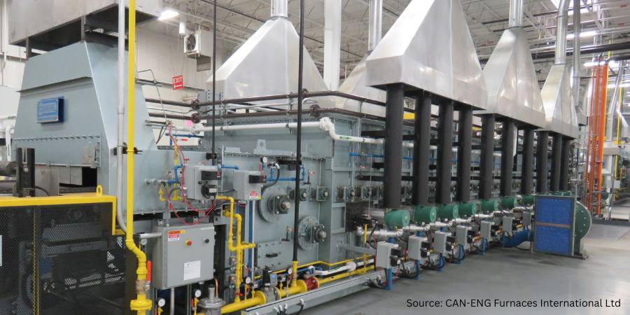
Two different specialty automotive components manufacturers have expanded their heat treating processing lines in order to meet the growing needs of their clients. The new furnace equipment will replace existing systems and bolster oil quench hardening and salt quench austempering capabilities.
CAN-ENG Furnaces International Ltd, based in Niagara Falls, ON, Canada, will supply mesh belt furnace systems, oil quench and salt quench systems, post quench wash systems, CAN-ENG PET™ SCADA system, and integrated controls. The automotive parts manufacturers chose designs that provide low energy consumption, reduced part mixing, reduce part damage and part distortion potential, and high uptime productivity.
The press release is available in its original form here.
In this episode of Heat TreatRadio,Doug Glenn discusses the hardenability of materials with guest Michael Mouilleseaux, general manager at Erie Steel LTD. Michael walks us through how to interpret hardenability charts and provides detailed insights on reading these charts, including addressing the importance of understanding the nuances of complicated part geometry.
Below, you can watch the video, listen to the podcast by clicking on the audio play button, or read an edited transcript.
The following transcript has been edited for your reading enjoyment.
Understanding a Hardenability Chart (01:59)
Doug Glenn: What I’d like to do is talk through this chart and learn how to read this a little bit better. And I’d like to ask questions about it because I’m not familiar with this, and I’m sure there are going to be some listeners and viewers who aren’t familiar with it. This will be just a quick tutorial on how to read these charts.
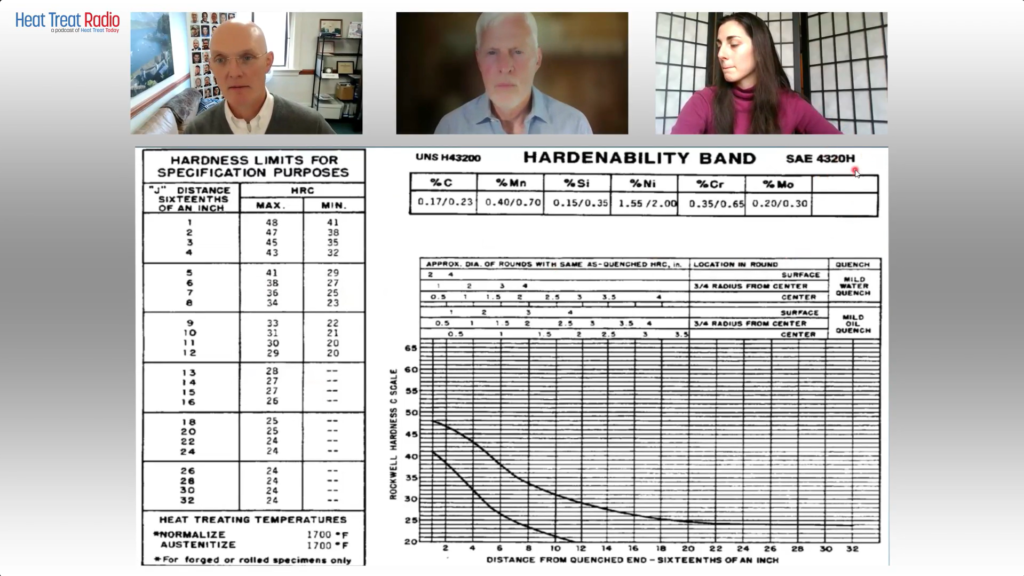
Go to the upper, right-hand corner. First off, SAE 4320H is the grade of the steel that we’re talking about?
The Heat Treat Lunch & Learn crew: Doug Glenn, Publisher of Heat Treat Today; Michael Mouilleseaux, General Manager at Erie Steel LTD.; Bethany Leone, Managing Editor of Heat Treat Today Use this chart to follow along with the conversation. Source of chart: Erie Steel, Ltd.
Michael Mouilleseaux: Correct.
Doug Glenn: Then the table right below that you’ve got percentage C (carbon). Is Mn manganese?
Michael Mouilleseaux: Manganese.
Doug Glenn: Thank you very much. Silicon, nickel, chrome, moly. My question is about those ranges. Is this basically saying the percentage carbon on the far left in 4320H goes anywhere from 0.17–0.23?
Michael Mouilleseaux: That is correct.
Doug Glenn: Okay. So that’s variability right there. All of those are basically telling you what the ranges are in those alloys in this grade of steel?
Michael Mouilleseaux: That is correct.
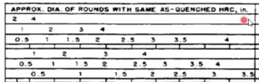
Doug Glenn: Then you go down to the top columns of this table below, and it says “Approximate diameter of rounds with same as quenched HRC in inches.” Right?
Approximate diameter of rounds with same as quenched HRC in inches Source: Erie Steel, Ltd.
Michael Mouilleseaux: Yeah. Essentially, the first three rows are for water quenching. And the bottom three are for oil quenching.
Doug Glenn: If you go over to the second major column called “Location in round,” what’s the size of the round we’re working on here?
Michael Mouilleseaux: It can vary. Go down to where it says, “Mild Oil Quench,” then left to “Surface,” then left then go to “2 inches.” Then, go straight down to the bottom, and that’s approximately J5. So, the “Distance from Quenched End — Sixteenths of an Inch” is Jominy position 5.
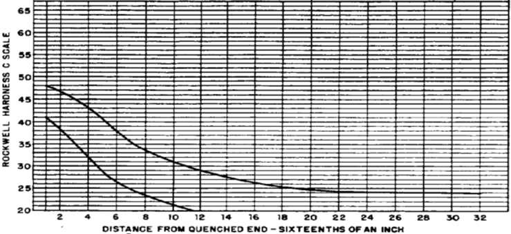
Michael Mouilleseaux: If you go to Jominy position 5 on the left-hand chart, you can see the hardness limits for that; the maximum is Rockwell C 41, and the minimum is Rockwell C 29. So, the chemistry can vary provided the hardenability at J5 is 29–41.
Doug Glenn: That’s the acceptable range?
Michael Mouilleseaux: That’s the acceptable range. That’s one way of looking at it. The chemistry would allow you to do that.
Now, go back to the chart on the right-hand side and to “Surface,” move down one row to “¾ radius from center,” and go left to two inches. Moving down from there you see that is Jominy position 8. So, the surface of a two-inch round is Jominy position 5, and the ¾ radius is Jominy position 8.
If you go to the hardness chart on the left-hand side, that says that if you had a two-inch round of 4320H, and it was oil quenched, and you check the hardness at ¾ radius, then the expectation is that it would be 23–34.
Now, go back to the same chart that we were just at, and go to the “Center” row of “Mild oil quench.” Continue left to two inches, and that’s J12. Go back to the left-hand chart, and J12 is 20–29 in the center of the part.
So, the surface of the part could be 41, ¾ radius, center of the part would be 34, and the center of the part would be 29.And that would all meet the criteria.
Doug Glenn: The maximum for J5 would be 41.But at J12 you could get a 20 in the middle.
Michael Mouilleseaux: Right. That is one way to look at this chart. But there is another way.
Notice that it says “rounds.”There are some nuances to having flats and rectangles because, if you think about it, for the cross-sectional area of a rectangle, the hardenability is going to be determined by the direction that it is thinnest, not by the direction that it is thickest.
Take a gear tooth, for example: in the chart that we just made up the gear teeth, the root of the gear was about a half inch, just slightly more; and if we go to this same chart, go to “Center” of “Mild oil quench,” and then go to a “0.5 inch,” and when you go straight down, that’s the J3.
Is a gear necessarily a round? Of course, the answer to that is no. So, in complex shapes you can use this data, but you have to interpolate it in order to understand it.
To some extent, the first time you run this, you’re going to say, “I have a gear, and the root is a half inch across. And I know that the J3 is 40. And I’ll run this part, and I’ll section it and I’ll measure it and it’s 40. And I’ll say that’s a good approximation of that.” And experientially, you build confidence in this, that is, it’s your operation, your quenching operation, and your components. It allows you to interpolate these, and they become extremely useful.
So, is it definitive? No. Is it useful? Yes.
Doug Glenn: It gives you a ballpark, right? I mean, it’s giving you something, maybe guardrails.
Michael Mouilleseaux: It gives you a ballpark; it gives you guardrails. And I can tell you that after having run gear product in the same equipment for ten years, I can say that it’s definitive. I can say that if I have this hardenability, and I get this hardenability number for this heat, and these gears are made from this heat of steel, and it has a J3 of 42. If I’m at 38, I know something is going on other than just hardenability. And, at that point, I would suspect my heat treat operation.
Doug Glenn: Yeah. I have one more question about this chart: On the bottom right part of the graph there are two plot lines on there. What do those represent? I was thinking one represented the water quench and the bottom one represents the oil quench.
Plot lines representing maximum hardenability and minimum hardenability Source: Erie Steel, Ltd.
Michael Mouilleseaux: The top one represents the maximum hardenability. And the lower the lower one represents the minimum hardenability.
Doug Glenn: That’s your band. Okay. Those are basically your values over on the left-hand side then. Very good.
I don’t know about you, but I found that helpful. I really didn’t ever know how to read these tables. So, maybe someone else will find that useful. Thanks, Michael. I appreciate your expertise.
Michael Mouilleseaux: It’s been my pleasure.
About The Guest
Michael Mouilleseaux General Manager at Erie Steel, Ltd. Sourced from the author
Michael Mouilleseaux is general manager at Erie Steel LTD. Mike has been at Erie Steel in Toledo, OH, since 2006 with previous metallurgical experience at New Process Gear in Syracuse, NY, and as the Director of Technology in Marketing at FPM Heat Treating LLC in Elk Grove, IL. Having graduated from the University of Michigan with a degree in Metallurgical Engineering, Mike has proved his expertise in the field of heat treat, co-presenting at the 2019 Heat Treat show and currently serving on the Board of Trustees at the Metal Treating Institute.
The SECO/WARWICK Group, the parent company of SECO/VACUUM Technologiesand SECO/WARWICK USA, has announced plans to bolster its production capacity in the U.S., increasing its footprint and workforce. The expansion will include relocating a portion of its manufacturing and a metallurgical lab for vacuum furnaces from its headquarters site in Poland to Crawford County, Pennsylvania.
The 120,000-sq ft facility located in Meadville, PA, will house equipment for furnace production and serve the company’s North American customers through the addition of parts, service, and training capacity, resulting in an increase in its heat treat manufacturing workforce. an international furnace manufacturer
SECO/WARWICK Group announced that this expansion received support from the Commonwealth of Pennsylvania through a $2 million package of matching fund grants from the Department of Community and Economic Development (DCED) through its Redevelopment Assistance Capital Program (RACP). The primary use and intent of RACP funds is for reimbursement of eligible construction costs which SECO/WARWICK Group companies will match on a 1:1 basis. The Commonwealth will also provide an additional $69 thousand in matching funds for job training through the Workforce & Economic Development Network (WEDnet).
Employees of SECO/VACUUM Technologies and SECO/WARWICK at the announcement of the Meadville, PA, site expansion, held jointly by The SECO/WARWICK Group and the Commonwealth of PA Department of Community and Economic Development Source: Heat Treat Today
State, county and local officials as well as representatives from the international and US-based offices of the SECO/WARWICK Group were present at an event marking the expansion.
“Governor Shapiro is committed to making Pennsylvania an economic leader by investing in the growth of businesses like SECO/VACUUM and SECO/WARWICK,” stated the Commonwealth in the grant award letter. “In addition to the financing package outlined above, the Governor’s Action Team is prepared to provide both companies with any assistance that may be required throughout the application process, as well as to coordinate the involvement of all other state agencies in the project.”
“We look forward to working with our local partners including the City of Meadville, the Economic Progress Alliance of Crawford County (EPACC), the Workforce and Economic Development Network (WEDnet), and the Pennsylvania Department of Community and Economic Development (DCED) to make this expansion happen!” said Piotr Zawistowski, president and managing director of SECO/VACUUM.
Pictured in feature image (L to R): Don Marteeny, vice president of engineering; Slawomir Wozniak, president and CEO, SECO/WARWICK Group; Piotr Zawistowski, president and managing director of SECO VACUUM Technologies
The press release is available in its original form here.
Three elements in the T6 aluminum heat treatment process — high temperature solution heat treatment, drastic temperature change in the water quench, and a long age hardening process — challenge accurate temperature monitoring. Thru-process technology gives in-house heat treaters the power to control these variables to overcome the unknowns. In the following Technical Tuesday article, Dr. Steve Offley, “Dr. O”, product marketing manager at PhoenixTM, examines the path forward through the challenges of aluminum heat treating.
This informative piece was first released in Heat Treat Today’s August 2024 Automotive print edition.
Aluminum Processing Growth
In today’s automotive and general manufacturing markets, aluminum is increasingly becoming the material of choice, being lighter, safer, and more sustainable. Manufacturers looking to replace existing materials with aluminum are needing new methodology to prove that thermal processing of aluminum parts and products is done to specification, efficiently and economically.
To add strength to pure aluminum, alloys are developed by the addition of elements dissolved into solid solutions employing the T6 heat treatment process (Figure 1). The alloy atoms create obstacles to dislocate movement of aluminum atoms through the aluminum matrix. This gives more structural integrity and strength.
FIgure 1. Critical temperature phase transitions of the T6 aluminum heat treatment process Source: PhoenixTM
Process temperature control and uniformity is critical to the success of T6 heat treat to maximize the solubility of hardening solutes such as copper, magnesium, silicon, and zinc without exceeding the eutectic melting temperature. With a temperature difference of typically 9–15°F, knowing the accurate temperature of the product is essential. Control of the later quench process (Figure 1, Phase 3) is also critical not only to facilitate the alloy element precipitation phase but also to prevent unwanted part distortion/warping and risk of quench cracking.
T6 Process Monitoring Challenges
The T6 solution reheat process comes with many technical challenges where temperature profiling is concerned. The need to monitor all three of the equally important phases — solution treatment, quench, and the age hardening process — makes the trailing thermocouple methodology impossible.
Figure 2. Thru-process temperature monitoring of the three T6 heat treatment phases Source: PhoenixTM
Even when considering applying thru-process temperature profiling technology, sending the data logger through the process, protected in a thermal barrier (Figure 2), the T6 heat treat process comes with significant challenges. A system will not only need to protect against heat (up to 1020°F) over a long process duration but also withstand the rigors of being plunged into a water quench. Rapid temperature transitions create elevated risk of distortion and warping which need to be addressed to give a reliable and robust monitoring solution.
Certain monitoring systems can provide protection to the data logger at 1022°F for up to 20 hours (Figure 3).
Figure 3. Thru-process temperature profiling system installed in the product cage monitoring the T6 heat treatment (solution treatment, quench, and age hardening) of aluminum engine blocks
Thermal Protection Technology
To meet the challenges of the T6 heat treat process, the conventional thermal barrier design employing microporous insulation is replaced with a water tank design, with thermal protection using an evaporative phase change temperature control principle. Evaporative technology uses boiling water to keep the high temperature data logger (maximum operating temperature of 230°F) at a stable operating temperature of 212°F as the water changes phase from liquid to steam. The advantage of evaporative technology is that a physically smaller barrier is often possible. It is estimated that with a like for like size (volume) and weight, an evaporative barrier will provide in the region of twice the thermal protection of a standard thermal barrier with microporous insulation and heat sink. The level of thermal protection can be adjusted by changing the capacity of the water tank and the volume of water. Increasing the volume of water increases the duration at which the T6 temperature barrier will maintain the data logger temperature of 212°F before it is depleted by evaporation losses.
The TS06 thermal barrier design (Figure 4) incorporates a further level of protection with an outer layer of insulation blanket contained within a structural outer metal cage. The key role of this material is to act as an insulative layer around the water tank to reduce the risk of structural distortion from rapid temperature changes both positive and negative in the T6 process.
Figure 4. TS06 thermal barrier design showing water tank, housing the data logger at its core, installed within structural frame containing the insulation blanket surface layer; water tank shown with traditional compression fitting face plate seal Source: PhoenixTM
Obviously, the evaporative loss rate of water is governed by the water tank geometry. A cube shaped tank will provide the best performance, but this may need to be adapted to meet process height restrictions. A TS06 thermal barrier with dimensions 8.5 x 18.6 x 25.2 inches (H x W x L) offering a water capacity of 3.5 US gallons provides 11 hours of protection at 1022°F. A larger TS06 with approximately twice the capacity 12.2 x 18.6 x 25.2 inches (H x W x L) and 7.7 US gallons gives approximately twice the protection (20 hours at 1022°F).
Innovative IP67 Sealing Design
Passing through the water quench, the data logger needs to be protected from water damage. This is achieved in the system design by combining a fully IP67 sealed data logger case and water tank front face plate through which the thermocouples exit. Traditionally in heat treatment applications, mineral insulated thermocouples are sealed using robust metal compression fittings. Although reliable, the compression seals are difficult to use, requiring long set-up times. The whole uncoiled straight cable length must be passed through the tight fitting which, for the 10 x 13 ft thermocouples, takes some patience. Thermocouples can be used and installed for multiple runs, if undamaged. Unfortunately, as the ferrule in the compression fitting bites into the MI cable, removal of the cable requires the thermocouple to be cut, preventing reuse.
To overcome the frustrations of compression fitting, an alternative innovative thermocouple sealing mechanism has been designed for use on the T6 thermal barrier (Figure 5).
Figure 5. TS06 thermal barrier IP67 bi-directional rubber gasket seal; installation of mineral-insulated (MI) thermocouples and RF antenna aerial
Thermocouples can be slotted easily and quickly, tool free, into a precision cut rubber gasket without any need to uncoil the thermocouple completely. The rubber gasket has a unique bi-directional seal, allowing both sealing of each thermocouple but also sealing of the clamp face plate to the data logger tray, which is then secured to the water tank with a further silicone gasket seal. The new seal design allows thermocouples to be uninstalled and reused, reducing operating costs significantly.
Accurate Process Data considerations
The T6 applications come with a series of monitoring challenges which need to be considered carefully to guarantee the quality of the data obtained. Although the complete process time of the three phases can reach up to 10 hours, it is necessary to use a rapid sample interval (seconds) to provide a sufficient resolution. The data logger is designed to facilitate this with a minimum sample interval of 0.2 seconds over 20 channels and memory size of 3.8 million data points, allowing complete monitoring of the entire process. A sample interval of 0.2 seconds provides sufficient data points on the rapid quench cooling curve. The high resolution allows full analysis and optimization of the quench rate to achieve required metallurgical transitions yet avoid distortion or quench cracking risks.
Employing the phased evaporation thermal barrier design, the high temperature data logger with maximum operating temperature of 230°F will operate safely at 212°F. During the profile run, the data logger internal temperature will increase from ambient temperature to 212°F. To allow the thermocouple to accurately record temperature, the data logger offers a sophisticated cold junction compensation method, correcting the thermocouple read out (hot junction) for anticipated internal data logger temperature changes.
Data logger and thermocouple calibration data covering the complete measurement range (not just a single designated temperature) can be used to create detailed correction factor files. Correction factors are calculated by interpolation between two known calibration points using the linear method as approved by CQI-9 and AMS2750G. This method ensures that all profile data is corrected to the highest possible accuracy.
Addressing Real-Time, Thru-Process Temperature Monitoring Challenges
For a process time as long as the T6, real-time monitoring capability is a significant benefit. The unique two-way RF telemetry system used on the PhoenixTM system helps address the technical challenges of the three separate stages of the process. The RF signal can be transmitted from the data logger through a series of routers linked back to the main coordinator connected to the monitoring PC. The wirelessly connected routers are located at convenient points in the process (solution treatment furnace, quench tank, aging furnace) to capture all live data without any inconvenience of routing communication cables.
A major challenge in the T6 process is the quench step from an RF telemetry perspective. An RF signal cannot escape from water in the quench tank. To overcome this limitation, a “catch up” feature is implemented. Once the system exits the quench and the RF signal is re-established, any previously missing data is retransmitted guaranteeing full process coverage.
Process Quality Assurance and Validation
In the automotive industry, many operations will be working to the CQI-9 special process heat treat system assessment accreditation. As defined by the pyrometry standard, operators need to validate the accuracy and uniformity of the furnace work zone by employing a temperature uniformity survey (TUS).
The thru-process monitoring principle allows for an efficient method by which the TUS can be performed employing a TUS frame to position a defined number of thermocouples over the specific working zone of the furnace (product basket). As defined in the standard with particular reference to application assessment process Table C (aluminum heat treating), the uniformity for both the solution heat treatment and aging furnace needs to be proven to satisfy ±10°F of the threshold temperature during the soak time.
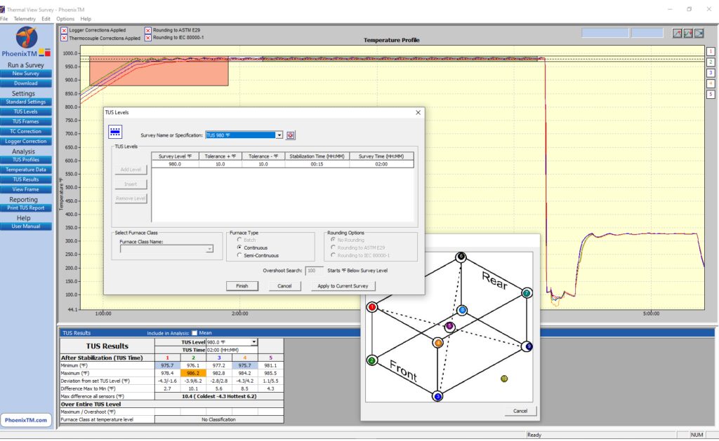
Complementing the TUS system, the Thermal View Survey software provides a means by which the full survey can be set up automatically allowing routine full analysis and reporting to the CQI-9 specification as shown in Figure 6.
Figure 6. View of TUS for T6 aluminum processing in Phase 1 Solution Re-heat Source: PhoenixTM
Interestingly, a significant further benefit of the thru-process principle is that by collecting process data for the whole process, many of the additional requirements of the process Table C can be achieved with reference to the quench. From the profile trace, key criteria such as quench media temperature, quench delay time, and quench cooling curve can be measured and reported with full traceability during the production run.
Summary
To fully understand, control, and optimize the T6 heat treat process, it is essential the entire process is monitored. Thru-process monitoring solutions, designed specifically, allow not only product temperature profiling of all the solution heat treatment, water quench, and age hardening phases, but also comprehensive temperature uniformity surveying to comply with CQI-9.
About the Author:
Dr Steve Offley (“Dr O”), Product Marketing Manager, PhoenixTM
Dr. Steve Offley, “Dr. O,” has been the product marketing manager at PhoenixTM for the last five years after a career of over 25 years in temperature monitoring focusing on the heat treatment, paint, and general manufacturing industries. A key aspect of his role is the product management of the innovative PhoenixTM range of thru-process temperature and optical profiling and TUS monitoring system solutions.
Asimco Shuanghuan Piston Ring Co., Ltd. has added a third nitriding system to its heat treating operations, enhancing piston ring production capabilities to serve a range of applications, including the automotive, commercial vehicle, construction machinery, and marine sectors. The compact furnace system was installed in line with two identical systems acquired in 2018 and 2021.
Nitrex installed the latest nitriding system in June, 2024, and Asimco began production in July with a goal to increase its annual production capacity of 180 million pieces and over 4,800 different varieties and specifications. Nitrex’s NITREG®-S stainless steel nitriding technology improves wear resistance, corrosion resistance, fatigue strength, surface hardness, and dimensional stability of piston rings, while reducing friction. These improvements result in better sealing, lower oil consumption, and overall enhanced engine efficiency and durability.
Nikola Dzepina Nitrex Regional Manager – Asia Source: NITREX
“The addition of the NXK-812 furnace aligns with Asimco Shuanghuan’s objectives to boost production volume and ensure precision and reliability in high-volume manufacturing,” said Tao Liu, sales manager at Nitrex China.
“By incorporating an additional Nitrex system into their operations, Asimco enhances its ability to produce stainless-steel piston rings with superior performance, durability, and reliability. This advanced treatment makes their products exceptionally suited for high-demand engine applications,” said Nikola Dzepina, account executive at Nitrex.
The press release is available in its original form here.