Avoid Costly Refractory Repairs with Proper Maintenance
Refractories, “the unsung hero of the manufacturing process,” can’t measure up to that moniker if their superpowers are worn down and not getting due maintenance. Guest columnist Pamela Gaul, director of marketing at Plibrico Company, LLC, examines the critical role the refractory lining plays in the success of manufacturing aluminum, why a refractory is susceptible to cracking under extreme conditions, and how to select and prepare refractory linings to achieve a longer service life.
Read more Maintenance columns in previous Heat Treat Today’s issues here.
As the old saying goes, “An ounce of prevention is worth a pound of cure.” This is certainly true when it comes to your refractories.
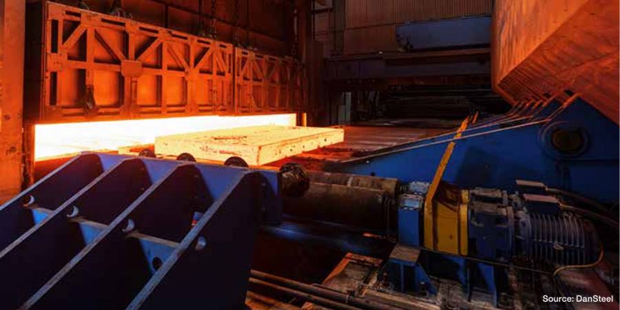
Manufacturers around the world rely on refractories to safeguard their multi-million dollar industrial-grade boilers, incinerators and furnaces from thermal damage and corrosion brought on by operating temperatures that can reach 3000°F (1650°C).
Without refractories — the unsung hero of the manufacturing process — it would be impossible to process the raw materials that go into automobiles, chemicals, power-generation equipment, buildings, roads and much more. As such, it only makes good financial and business sense to provide basic refractory maintenance for your machinery. By protecting your critical heat-processing equipment, you can minimize costly downtime, reduce energy losses, prevent employee injuries and, more importantly, avert a catastrophic equipment failure.
Given refractories’ importance to operations, it is important to remember that they are consumables and will wear out. This is significant because without proper maintenance your processing equipment may fail at the most inopportune time, and downtime for a furnace or dryer — even one day — can cost a company hundreds or thousands of dollars. The rewards of proper maintenance far outweigh the expense.
It is also important to remember that refractories are not commodities. Even within the general classification of refractories, there are significant variances in chemical compositions. As a result, refractories will have different maintenance schedules and repair practices.
Refractory maintenance has a cost. That is why maintenance needs must be factored in when evaluating which refractories to install in your application. For example, the upfront costs of engineered shapes may be 20-30% more than monolithic refractories. However, they require little to no dryout, are easy to install and in some cases last longer than some traditional castables. Also, if there are high-wear areas that may be difficult to reach due to their location or geometry, financially it is well worth going with the precast shapes to minimize future maintenance expense.
The Wear Factor
What causes refractories to wear? Time, temperature, corrosive gases, slag and operational practices will all take their toll, as will the overall engineering of the heat-processing equipment. Other culprits leading to the degradation of a refractory lining can be incorrect combustion controls, improper flame set-up, anchor failure or thermal shock resulting from severe temperature fluctuations. More times than not it is a combination of these or other factors that lead to refractory damage — not a single cause.
Not following the manufacturer’s recommended curing and dryout schedule can also lead to degradation. If an end-user is looking to accelerate the process due to production demands, quick dryout products might be a good option.
Some manufacturers offer refractory materials that provide reductions in dryout time and may offer nearly the same properties as their traditional, non-fast dryout counterparts. The benefit to these quick-cure/dryout products are that dryout times are cut about in half, which can represent a time savings of up to 40-50 hours. While they offer an easy, time-saving solution, however, there are limitations to their material properties as well as cautions on dryout.
It is a good idea to use the dryout time to check items such as the vessel pressurization, exhaust system, temperature monitor, thermocouple position and moisture wicking.
How You Can Help with Refractory Longevity
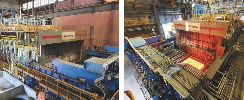
The goal of periodic inspection, maintenance and repair is to ensure the longevity and performance of refractories (Fig. 1). During maintenance, worn parts and areas of excessive wear are repaired before turning into bigger issues.

Depending on operational make-up, skills and budget, employing a permanent staff to perform these services might not make financial sense. Instead, working with an outside professional refractory contractor with extensive industry expertise who can provide maintenance services, emergency response and repair operations might be far more cost-efficient for the end-user.
Under either service structure, there are precautionary steps that can be taken in-house to extend refractory operation and increase longevity.
- Furnace heat up and cool down: Follow procedures established by the furnace manufacturer. Proper heating creates positive pressure in a furnace, ensuring an equal distribution of temperature. Expansion or contraction control is vital to avoid damage to the refractory.
- Dust removal: Keep the dust off the steel in roofs that have an exposed anchoring structure. This simple step keeps the stainless steel hardware from becoming too hot and fatiguing.
- “Good” cracks vs. “bad” cracks: Understand the important differences between good cracks and bad cracks. Good cracks in the refractory are created and visible as part of the natural cool-down process. These should be left alone because they will disappear during the heat-up process. If the end-user fills “good” cracks, they will have problems down the road with shell bulge because the refractory will naturally expand during heat-up and production.
An Ounce of Prevention

Develop a relationship with a reliable, knowledgeable and nimble professional refractory expert who has your best interests at heart. During the inspection process, your expert and their refractory team should provide you with a comprehensive condition assessment to help determine the need for repair. Assessments allow the refractory contractor to analyze the state of the refractory and select the proper solution to ensure durable repair.
Often, the first indication that there might be a problem with the refractory lining is the appearance of a “hot spot” on the shell. A hot spot is where an area of the shell is found to be operating at a higher temperature than the surrounding area. This can be due to cracking, spalling or other issues that result in deterioration of the refractory lining.
When hot spots are identified, the refractory professional will typically pack, grout, caulk or “stuff” the area if it is accessible from the outside. They may also “hot gun” from the inside.
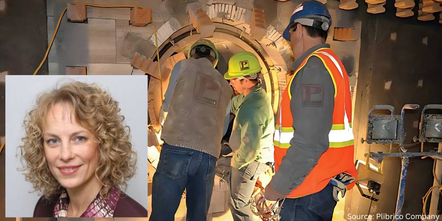
The number and severity of hot spots, usually found using an infrared camera and heat-flow analysis, can help the refractory professional or engineer determine the integrity of the refractory lining. Depending on the results, the manager/engineer should perform a full cost-benefit analysis to help evaluate which is the best option — repair or complete lining replacement (Fig. 2).

When faced with any type of refractory repair, best practice will come down to scope and timetable. A quick repair may be addressed using a gunning (cold/hot) or shotcrete refractory technique. Another possibility might be ramming plastic refractory just to fill a hole/spall or resurface the lining.
A more time-consuming and sometimes better option would be a full lining repair. These repairs are done to a more thorough degree, which allows for proper cure, dryout and anchoring.
A Pound of Cure – Premature Failure
Without proper refractory maintenance, you run the risk of premature failure of the refractory lining. The funny, or not so funny, thing about refractory failures is that you will usually not receive a notice on that day telling you that one of your critical systems will be failing. And once a failure occurs, it is all-hands-on-deck to address the issue and bring your operation back online as quickly as possible.
During the process, you or your refractory expert should collect samples of the existing refractory material to help identify the causes of failure. For example, glazing and excessive shrinking indicate exposure to excessive temperatures. Shearing away of the top refractory service can be evidence of thermal shock.
In addition, calculating a base-to-acid ratio will show if the type of refractory installed should have been selected in the first place. Refractory materials are manufactured to operate in different environments. A properly selected and installed refractory lasts longer, helps minimize shutdowns and leads to better fuel efficiency.
Lastly, fuel should be checked to determine if it is contributing to the degradation of the refractories. For instance, moisture content in fuel may be too high or contain chemicals that damage the lining.
Financial Implications of Non-Compliance
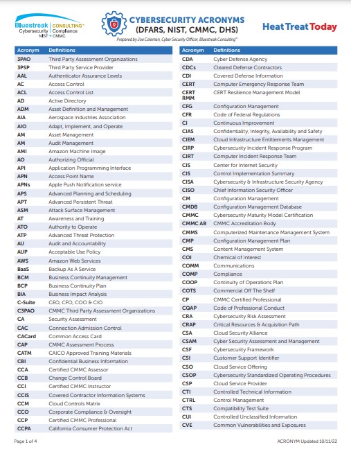
Compliance with CMMC 2.0 can be financially burdensome. Implementing measures such as multi-factor authentication, encryption and continuous monitoring can be costly, especially for businesses with limited resources. The lack of in-house cybersecurity expertise compounds this issue, requiring companies to hire or train specialized personnel, further increasing costs.
Failing to comply with CMMC 2.0 could result in losing valuable DoD contracts, which can be a significant portion of SMB revenue. Such losses could lead to layoffs, revenue declines or even business closures.
Drama-Free Refractory Removal and Replacement
In some cases, the maintenance needed for heat-processing equipment is more than repairs can handle. This leaves complete refractory lining replacement as the only option. This is highly specialized work requiring the skills of an experienced refractory installer.
To ensure drama-free refractory removal and replacement, follow these five key tips:
- Enlist the support of a seasoned, knowledgeable and professional refractory contractor. Not all contractors are experts in refractory work. Make sure the contractor has quick access to refractory material.
- Obtain a complete scope of work (SOW) and a solid plan. Some of the items that should appear in a good SOW include:
- Amount of material needed and on hand
- List of equipment supplied
- Schedule and details for the tear-out plan
- Proper curing/dryout plan
- Prepare for the unforeseen. Often, problems do not reveal themselves until the unit has cooled and the tear-out begins. This reality necessitates contingency plans to be in place. Further, it underscores the importance of working with a fully stocked professional refractory contractor who has access to a refractory manufacturer that uses just-in-time manufacturing principles.
- Where applicable, install and use precast shapes. These shapes are ready to install and require little to no dryout.
- Discuss with your refractory expert if fast-dryout refractory material may be an option for you. Incorporating quick-dryout materials like Plibrico’s FastTrack® can cut traditional dryout time in half.
When working with your refractory installer, it is important to focus on your specific application to drive refractory material requirements. It is easy to get caught up in flashy new refractory compositions and features. The application should determine the refractory material, not the other way around.
Good for Your Equipment, Good for Your Wallet
Proper refractory maintenance is not only good for your critical heat-processing equipment, but also for your wallet. The reality is that the life of your refractory can be reduced by as much as 50% (or more) without proper maintenance. In fact, failing to provide basic refractory maintenance for an aluminum furnace, for example, can leave the end-user with an unbudgeted and unexpected bill for $150,000 or more to fully replace the roof. This is an expense that might have been put off many years with properly maintained refractory. It could then have been scheduled, budgeted and drama-free.
Worse yet, in the event of catastrophic refractory failure where the anchor tile system or full wall is snapped, the repair bill can easily top $200,000. Keep in mind these figures only address repairs. Add on the large cost of lost production and the total skyrockets quickly!
As Benjamin Franklin would agree, take care of your refractory — the unsung hero of the manufacturing process — and it will take care of you with a safe and efficient work environment, minimized downtime, reductions in energy losses and, more importantly, avoidance of catastrophic critical heat-processing equipment failure.
About the Author

Director of Marketing
Plibrico Company
Pamela Gaul is the director of marketing at Plibrico Company LLC.
For more information: Visit www.plibrico.com.
This article was initially published in Industrial Heating. All content here presented is original from the author.
Find Heat Treating Products And Services When You Search On Heat Treat Buyers Guide.Com
Avoid Costly Refractory Repairs with Proper Maintenance Read More »