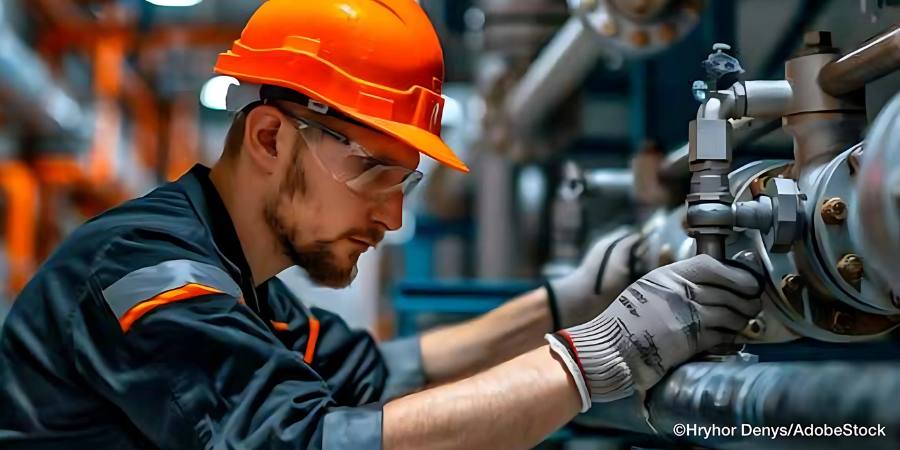
In each installment of Combustion Corner, Jim Roberts, president of U.S. Ignition, reinforces the goal of the series: providing informative content to “furnace guys” about the world of combustion. The previous column examined the air supply inlet — the inhale, and this month, Jim is examining the exhaust system — the exhale, and how to inspect it, maintain it, and manage it.
This informative piece was first released in Heat Treat Today’sMarch 2025 Aerospace print edition.
A guy walks into a room full of furnace guys and says, “Is it just me, or is it a tad stuffy in here?”
We have all been able to imagine that it is hard to focus and do your job in an environment where it seems like it’s hard to breathe. Well, our hard workin’ buddy, the furnace, is continually stuck in a cycle of trying to breathe in, breathe out — and then somewhere in between, the magic of combustion and heat happens! We talked last month about the “breathe in” part of the combustion process. This month, we are going to remind you that if you take a really good, productive, inhaled, life giving breath, you are probably going to want to exhale at some point, too!
Tip 2: Ensure Exhaust Systems Are Properly Functioning and Clean
Inhale, exhale. It makes sense that if we were earlier having issues with the air supply inlet, the exhaust should also be checked. Today’s combustion equipment is sophisticated and sensitive to pressure fluctuations. If the exhaust is restricted, the burners will struggle to get the proper input to the process. I used to use the example of trying to spit into a soda bottle. Try it. It’s tough to do and invariably will not leave you happy. Clean exhaust also minimizes any chance of fire. Read on for three examples.
A. Check the Flues and Exhausts for Soot
If you are responsible for burners that are delivering indirect heat (in other words, radiant tubes), you have a relatively easy task ahead to check the flues/exhausts. Each burner usually has its own exhaust, and one can see if the burners are running with fuel-rich condition (soot/carbon). Soot is not a sign of properly running burners and will signal trouble ahead. Soot can degrade the alloys at a chemical level. Soot can catch fire and create a hot spot in the tubes. Soot obviously signals you are using more fuel than needed (or your combustion blower is blocked, see the first column in this series).
As a furnace operator or floor person, it should be normal operating procedure to look for leakage around door seals.
Here’s a sub tip: If you cannot see the exhaust outlets directly, look around the floor and on the roof of the furnace up by the exhaust outlets. Light chunks of black stuff is what is being ejected into the room when it breaks free from the burner guts (if it can). That will tell you it’s time to tune those burners. If you do not have a good oxygen/flue gas analyzer, get one. It can be pricey, but it will pay for itself in a matter of months in both maintenance and fuel savings.
B. Seriously … Check the Flues and Leakage Around Door Seals
If you are running direct-fired furnace equipment, or furnaces that have the flue gases mixed from multiple burners, it gets a little trickier. All the same rules apply for not wanting soot. Only now, it can actually get exposure to your product, it can saturate your refractory, and it can clog a flue to the point that furnace pressure is affected. An increase in furnace pressure can test the integrity of your door seals. It can back up into the burners and put undue and untimely wear and tear on burner nozzles, ignitors, flame safety equipment, etc. As a furnace operator or floor person, it should be normal operating procedure to look for leakage around door seals.
C. Utilize Combustion Service Companies
Ask the wizards. Combustion service companies can usually help you diagnose and verify flue issues if you suspect they exist. It’s always a great idea to set a baseline for your combustion settings. Service companies can help you establish the optimum running conditions. Again, money well spent to optimize the performance of your furnaces. I’m sure you already have a combustion service team; some are listed in this publication. Otherwise, consult the trade groups like MTI and IHEA for recommended suppliers of that valuable service.
Check flues monthly. It should be a regular walk around maintenance check.
Don’t let the next headline be your plant. See you next issue.
About The Author:
Jim Roberts President US Ignition
Jim Roberts, president at US Ignition, began his 45-year career in the burner and heat recovery industry directed for heat treating specifically in 1979. He worked for and helped start up WB Combustion in Hales Corners, Wisconsin. In 1985 he joined Eclipse Engineering in Rockford, IL, specializing in heat treating-related combustion equipment/burners. Inducted into the American Gas Association’s Hall of Flame for service in training gas company field managers, Jim is a former president of MTI and has contributed to countless seminars on fuel reduction and combustion-related practices.
Jim Roberts, president of U.S. Ignition, joins us in the renewal of the Combustion Corner column. In this installment, Jim establishes that the goal of the series is to provide informative content to “furnace guys” about the world of combustion, furthering the spirit of the Heat Treat Today motto: “We believe people are happier and make better decisions when they are well informed.”
This informative piece was first released in Heat Treat Today’sFebruary 2025 Air/Atmosphere Furnace Systems print edition.
Contact us with your Reader Feedback!
So … A guy walks into a room full of furnace guys …
And the story (or joke) begins again. I used to be one of the furnace guys. It’s a really niche group of strange, unique, and sometimes knowing people, who, by the way, are not gender specific. To me, “a guy” is a moniker as specific as saying that person over there is a swimmer.
But as furnace guys, those same individuals have a peek at the stuff that normal planet walkers don’t. They — or rather WE — know how to almost tame the beast. We have learned what it means to control temperatures that can crack stone. We can bend metal and make it do what we want at temperatures that the human eye cannot gaze upon without safety filters between us and the beast.
And what is this beast? It’s called combustion. It’s a phenomenon that allows the very air around us and anciently sourced resources to burn like hellfire and yet still do our bidding. But there are fewer and fewer guys who manage the beast these days. And that is how a column like this takes launch.
This publication, and its talented editorial staff, have always been driven to provide information that, in their own words, will allow the greater masses this privilege: “We believe people are happier and make better decisions when they are well informed.”
It was not lost on the staff that with dwindling numbers of longtime combustion people some of the benefits of being “well informed” were needed. They felt information could be presented in such a fashion that old-timers like me could share some of the tried-and-true techniques that we have used over the years. The hope is to not only make the workplace safer, but also to increase efficiency and performance in the processes that utilize combustion.
When we walk into almost any facility and go over to the underperforming furnaces, we can bet part of the problem will be inlet air source or exhaust outlet issues.
To some, this will seem like remedial information. That is GREAT. Because that means that you already understand a fair portion of the pathway to combustion performance. You can be the lead in your facility on combustion safety and understanding. Yay!
We are going to start with a visit to an article I wrote some time ago that then later became a pamphlet called “10 Combustion Tips.” It was written with plant maintenance guys in mind as they traveled the factories and facilities that they had responsibility for. We’ll turn this into a series of tips that are really intended for those less experienced to start. We’ll continue in upcoming editions of Heat Treat Today, and hopefully, everyone will feel like this was beneficial when cruising the aisles of your factories.
Tip 1: Keep the Process Air Filters Clean
I know, this seems so obvious, doesn’t it? Utilities tell us over and over to keep your home furnace filters clean. But I would be willing to bet that almost 30% of all furnace issues that we see in the field start at the blower supplying our combustion air. It’s the lungs for your burners! Any filter blockage will result in serious problems. As the system impedes under a clogged filter, your process may not get the required input. Clogged filters put undue strain on the combustion air blowers over time, so your electrical and motor maintenance costs may escalate. Additionally, the burners may go fuel rich. This wastes fuel and can create carbon, which at its best is an insulator. At its worst, it is a fire hazard.
Tip Solutions
A. Check the filters monthly: It is pretty easy to see if a filter is dirty. Your production folks may have even told you the furnace is slowing down. Less air, less heat. Take a peek … you will know. If it’s a fiber-based filter, replace it. Better yet, make it a habit to check filters every month.
B. Clean the screen: If not a replaceable filter, clean the metallic/plastic screen type with some solvent that will cut the machine/quench oil that’s probably the clog culprit. DO NOT put the filter back on dripping wet with solvent. I apologize to furnace guys out there for having to explain that, but it’s the new world, right? If you didn’t understand why, please refer to the movie “Back Draft.”
C. Get outside: Consider ducting an outside air source to the combustion air blower. Fresh air delivered at a stable temp will always help with furnace and burner performance.
So there, was that so hard? Nope, almost simple. And yet when we walk into almost any facility and go over to the underperforming furnaces, we can bet part of the problem will be inlet air source or exhaust outlet issues.
Don’t let it be your plant. See you next issue.
About the Author
Jim Roberts President US Ignition
Jim Roberts, president at US Ignition, began his 45-year career in the burner and heat recovery industry directed for heat treating specifically in 1979. He worked for and helped start up WB Combustion in Hales Corners, Wisconsin. In 1985 he joined Eclipse Engineering in Rockford, IL, specializing in heat treating-related combustion equipment/burners. Inducted into the American Gas Association’s Hall of Flame for service in training gas company field managers, Jim is a former president of MTI and has contributed to countless seminars on fuel reduction and combustion-related practices.
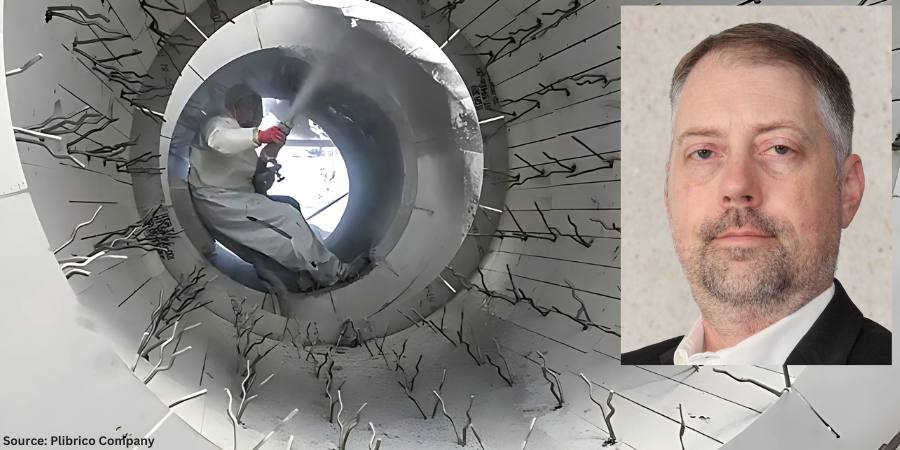
The faster the refractory installation, maintenance or repair, the more efficient and, by extension, profitable it is to the company, as savings fall to the bottom line. In this Technical Tuesday installment, Roger Smith, director of technical services at Plibrico Company, LLC, examines the challenges of insulation systems, taking a closer look at ultra-lightweight refractory gunite as a fast, flexible solution to controlling heat.
This informative piece was first released inHeat Treat Today’sFebruary 2025 Air/Atmosphere Furnace Systems print edition.
Manufacturers that rely on industrial grade furnaces, boilers and incinerators to produce their quality products are always looking for ways to improve. It is how they stay relevant and, more importantly, profitable. But you don’t get better just by desiring it. You need to identify better ways to get things done and introduce risk-neutral change to current operational processes. By some estimates, inefficient processes can reduce a company’s profitability by as much as one third.
Given refractories’ importance in safeguarding an operation’s multimillion-dollar thermal-processing equipment, and to avoid unscheduled downtime, it is smart business to have a sustainable maintenance and repair process in place. When a refractory situation does arise, the more proficient the process solution the better.
Controlling the Heat
Click the image above to read Roger Smith’s column on extending the life of refractory linings.
Furnace design is largely about controlling heat to maximize energy efficiency. An energy source — whether that is gas, coal, wood or electricity — is used to heat the furnace, and the furnace lining is designed to keep that heat inside the furnace. There are other factors to be considered, such as the environment inside the furnace, whether there is any abrasion or chemical interactions, or whether the furnace maintains a steady state temperature or undergoes temperature cycles. Regardless of what considerations have to be made for the hot-face lining, an insulation package must be used to reduce fuel consumption and control the cold-face temperature.
There are a large variety of insulation packages and materials that can be used in furnace design. Insulation comes in the form of board, fiber, brick and castables. Each type of insulation comes with its own sets of considerations, such as insulation value, installation method and cost. When considering the insulation package for the vertical wall of a furnace, support must also be considered because the insulation is expected to stay where it is placed and not slump over time. There also must be a means of connecting the hot-face working lining to the furnace structure to provide support. This is accomplished with an anchoring system that connects to the furnace shell and penetrates some distance into the dense hot-face working lining.
Anchoring Systems Challenge Insulation Installations
Anchors are considered to be the bones of a refractory installation and have several functions. They hold the refractory to the wall to keep it from falling in. They also prevent wall buckling due to the internal thermal stresses created by high temperatures. And, to a lesser degree, anchors can also help support the load of the refractory weight.
The anchoring system, however, can present big challenges when installing or maintaining the insulation. In most furnace applications, anchors are first welded directly to the furnace shell. Next, the insulation package is installed and finally the working lining. With anchors sticking off the furnace shell, installing insulation can become a challenge.
Fiber insulation in the form of blanket can be pressed into the gaps between the anchors, but it is important that the insulation remains in place during the life of the furnace. Industrial furnaces tend to vibrate, either from use of combustion or exhaust blowers or other process equipment. This constant vibration can cause fiber insulation to slump and lead to hot spots in the furnace wall due to the lack of insulation.
Figure 1. Anchoring systems are installed before refractory insulation and can pose challenges.
Insulation board is rigid enough to support itself on its end and can be found in a variety of densities and thicknesses to obtain the required insulation value. However, insulation board typically comes in sheets that will have to be cut to fit around the anchors. This can result in a significant amount of manpower and a significant amount of time in a furnace installation. The downtime of an industrial furnace can be costly, which often results in tens of thousands of dollars per hour in lost profits. For this reason, companies try to minimize the time spent rebuilding a furnace. Fewer man hours on a rebuild also tends to reduce the overall cost of the project.
Ultra-lightweight refractory gunites offer a means of installing a large amount of insulation in a relatively short period of time. A gunite is a monolithic refractory castable that is pumped dry through a hose under pressure and is mixed with water at the nozzle. Once the wet castable impacts the surface, it stiffens quickly to avoid slumping and hardens as it dries. This means that the gunite could be installed over the anchors with minimal time. The installer only needs to wrap the end anchors with masking tape to keep them clean for the working lining.
Figure 2. Cold-face and heat storage/loss graph for a production furnace
Distinct Differences in Refractory Gunites
Ultra-lightweight castables are a sub-set of the lightweight castables category but with a very important difference: density. For example, the average lightweight castable with a maximum service limit of 2400°F typically has a density of about 80–90 pcf (pounds per cubic foot). By comparison, ultra-lightweight castables with a maximum service limit of 2400°F will have a density of about 25–30 pcf.
This important distinction comes into play when looking at insulation thickness and calculating cold-face temperature. At the stated densities in a furnace operating at 2000°F, it would take nearly three times more lightweight castable than an ultra lightweight castable to achieve the same cold-face temperature — making many ultra-lightweight castables perfect for insulation and most lightweight castable refractories impractical to use as part of the total insulation package.
Ultra-lightweight castables that achieve final densities of 25–30 pcf while offering service temperatures above 2400°F are available through various refractory manufacturers. One such product, Plicast Airlite 25 C/G (aka Liquid Board) from the Plibrico Company, is designed to be installed via casting or gunite using conventional gunite equipment. With low thermal conductivity and thermal-shock resistance, this material is durable and quick to install. It also has advantages over insulation board, which has a labor intensive installation process of cutting around all the welded anchors, and fiber insulation, which can experience frequent hot spots due to slumping insulation. With an ultra-lightweight, Liquid Board-type of castable, it is possible to attain required insulation values and extended lining life with the installation speed of a refractory gunite.
Working With, Not Against, the Anchoring System
Let’s consider a real-life production furnace operating at 2000°F with a simple 9-inch refractory lining consisting of six inches of dense refractory and three inches of insulation. For comparison, we will assume an ambient air temperature of 81°F and eliminate any effects of exterior wind velocity. The dense refractory working lining for these examples is Pligun Fast Track 50, a 50% alumina, 3000°F-rated refractory gunite.
As seen in Figure 2:
Using three inches of ceramic fiber blanket at a density of 6 pcf, a cold face temperature of 252°F can be achieved.
Using three inches of insulation board at a density of 26 pcf, a cold face temperature of 247°F can be achieved.
Using three inches of an ultra lightweight gunite such as Plicast Airlite 25 C/G with a maximum service temperature of 2500°F and assumed density of 25 pcf, a cold-face temperature of 262°F is expected.
The calculated difference in cold-face temperature between insulation board and the ultra-lightweight gunite is 15°F, but the difference in installation time savings could be multiple shifts.
Figure 3. Ultra-lightweight gunite is quickly applied over anchors with standard equipment.
The cost of downtime can be incredibly high for any manufacturer, especially since downtime can result in a series of costs and losses (both tangible and intangible), including production, labor, replacement costs, product losses and, if unexpected, reputation damage. Industry resources estimate downtime can cost thermal processing companies between $250,000 and $1 million per hour. When multiplied over several shifts, this could mean millions of dollars in downtime costs. Not to mention that labor is a major contributor to the overall cost of a refractory project. The quicker the refractory installation, the less downtime and the more profitable the company.
For example, in an approximately 750-square-foot round duct application (cylinder) with anchors already installed, on average, installation of four inches of the different insulation types can be estimated at:
Fiber Insulation — 137 total labor hours, or ~5.5 square feet/hour
Insulation board — 288 total labor hours, or ~2.6 square feet/hour
Ultra-light gunite/Liquid Board — 80 total labor hours, or ~9.4 square feet/hour
The quick and easy installation of the ultra-light gunite/Liquid Board represents an average estimated financial savings in downtime of between $35 million and $130 million — savings that drops directly to a company’s bottom line. The time compression of installing gunite also holds an added advantage for the insulation installer because labor hours can come with a premium price tag and can sometimes be in short supply. All of this makes the ultra-lightweight gunite solutions an excellent choice to minimize downtime and rebuild costs while meeting the furnace design criteria.
Conclusion
Manufacturers that rely on industrial-grade furnaces, boilers and incinerators to produce their quality products are constantly looking for ways to reduce costs, increase profits and improve efficiencies by looking at and introducing risk-neutral change to current processes. Maintaining efficiency and avoiding unscheduled shutdowns of heat processing equipment requires maintenance. Selecting quality materials and risk neutral installation processes that minimizes maintenance completion times can help companies become more efficient.
About the Author:
Roger M. Smith Director of Technical Services Plibrico Company, LLC
Roger M. Smith, a seasoned professional in the refractory industry, is the director of technical services at Plibrico Company, LLC. With a master’s degree in Ceramic Engineering from the University of Missouri — Rolla, Roger has over 15 years of experience in the processing, development and quality assurance of both traditional and advanced ceramics. He has a proven track record in developing innovative ceramic formulations, scaling up processes for commercial production, and optimizing manufacturing operations.
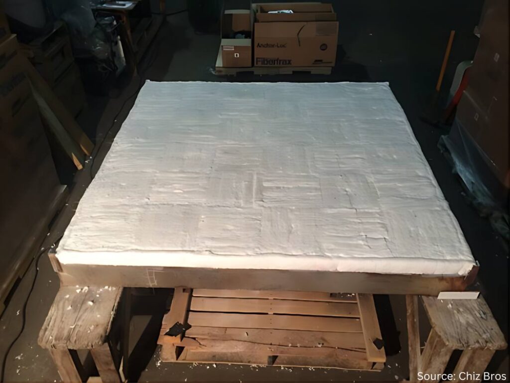
In this Heat TreatRadioepisode, Mark Rhoa, Jr. from Chiz Bros, a company specializing in ceramic fiber products, discusses insulation with host Doug Glenn. Mark focuses on the benefits of ceramic fiber in industrial applications. The conversation covers decarbonization, the importance of insulation and thermal shock resistance, the shift to electrically heated modules, and practical maintenance tips for ceramic fiber-insulated furnaces.
Below, you can watch the video, listen to the podcast by clicking on the audio play button, or read an edited transcript.
Doug Glenn:I want to welcome our guest today: Mark Rhoa Jr. from Elizabeth, Pennsylvania, near Pittsburgh. Mark’s been involved with the industry for quite a while with Chiz Bros, our sponsor for today. Mark is also aHeat TreatToday40 Under 40honoree from the Class of 2021. And, Mark, could you tell me who started your company — your dad or your dad and his brother? I don’t know the history that well.
Mark Rhoa: My dad actually joined the company in ‘97, but when he joined, Chiz Bros. had been around for a good 30 years or so. It was started by the Chiz brothers originally: Al, Ray, and John Chiz. As they got older and some of them moved on from the company to retire, my dad took over the company in 2014, and that’s when I came on board.
I’ve been here about ten years. And Ray Chiz Jr. just recently retired; he is one of the original owners’ sons who was working here running our warehouse. He’s the last with the Chiz name to work here. We say that the Chiz haircut is kind of what I’ve got going on. You can know by the haircut there’s a lot of Chiz’s still working here, and you might even be an honorary.
Doug Glenn: I can be an honorary, for sure. I don’t have enough on the side.
Chiz has been around for 50 some years doing specialty solutions for refractory applications in the metals, power, glass, and ceramics industries. And you guys deal with multinational companies as well as the small Ma and Pa shop furnace manufacturers or heat treaters/thermal processors, a pretty good mix. You’ve got great customer service, reasonable pricing, and quick delivery. And I know you and I have talked about how you guys pride yourselves on having a lot of stuff in stock. And finally, you guys have your Pittsburgh location and are also in Detroit, which is a relatively new addition, right?
Mark Rhoa: Yeah, about two years ago we opened up a Detroit warehouse. We’ve always had some good clients up that way. You’ve got to have some boots on the ground to be super effective. I say to get the easy orders you’ve got to have the stuff on the ground to get the hard orders, which are the phone calls at 5 o’clock on a Friday saying, “Hey, we need to pick this up because the furnace is down.” And we didn’t have that opportunity to improve our customer service up there before opening that location.
We try to punch above our weight to compete with the big guys on pricing. We make sure we’re always still answering the phone.
Doug Glenn: It makes a huge difference when you’ve actually got people answering the phone.
My understanding is that you provide castables, fibers, brick, etc. But today we want to hone in a little bit on ceramic fiber.
Mark Rhoa: Ceramic fiber is the big portion of our business. We’re one of the biggest Unifrax (Alkegen) ceramic fiber distributors in the country. So, a lot of what we do is being driven by ceramic fiber products we supply. We still can supply castables, bricks, and everything in between. But ceramic fiber drives the ship for us.
What Is Ceramic Fiber? (04:58)
Doug Glenn: Let’s talk about that. Most of our listeners are folks with their own in-house heat treat. But let’s assume we’ve got some people watching that don’t know some basics.
Tell us about ceramic fiber: What is it? How is it made? What are we using it for?
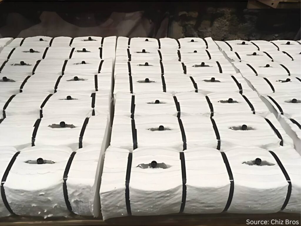
Mark Rhoa: I describe it to people who may not know much about it by comparing it to the Pink Panther insulation that people may recognize up in their roof or in their walls. Ceramic fiber is white, but picture that insulation for 2300°F. That’s what ceramic fiber is, and it’s a form that we sell the most of right now.
Ceramic fiber
You can take that and cut gaskets out of it. You can form it into hard boards through a vacuum forming process. You can take it folded into what we call ceramic fiber modules; your furnace probably has modules in it if it’s a traditional gas-fired or electric furnace. Ceramic fiber products typically aren’t used on the vacuum side of things. People with all vacuum furnaces are probably not going to be using ceramic fiber. There are cloths that are ceramic fiber based as well. There’s a bunch of other ways it’s used.
Ceramic fiber is made of a blown, spun glass. Essentially what you’re doing is dropping the liquid aluminum silica mixture, and it gets blown or blown and spun at super high temperatures. I’m not going to get into the details of the differences there, but whether the stream is blown or is spun on wheels will determine the tensile strength of blanket.
In the grand scheme of things, what you’re doing is collecting all that fiber and getting it onto a mechanism that’s moving along a conveyor belt. Then it’s getting needled from each side to interlock the fibers to make a 26” wide blanket. It’s going to be trimmed off an inch when it goes through, and at the end you have a 24” wide x 1” thick, 8-pound density roll coming out.
Those densities can vary based on how much fiber is going into it. It’s pounds per cubic foot. But when you’re using a 1” thick piece, it’s divided by twelve from a weight standpoint. The fiber you’re needling in there determines the density.
And there are slightly different chemistries for 2300°F, 2600°F, and the most expensive would be 3000°F polycrystalline. The process to make that is a little bit different, too.
But most people are probably more interested in what we’re doing with it. What’s the Chris Farley line in Tommy Boy? We’ll keep it PG, but “take a butcher’s word for it” — take our word for it; it’s made the right way.
Now we can get into how it’s actually used.
Doug Glenn: It’s basically like insulation in your house, like you said. That’s probably the best description of it for people that need to know. But it can obviously go to a much higher temperature.
In an industrial setting, why would you use fiber versus a castable or brick?
Why Fiber? (08:28)
Mark Rhoa: Ceramic fiber is a great insulator. We’ll probably get into why a better insulator is important for decarbonization efforts and things like that.
It’s certainly a better insulator than castables, easy to install, and easy to use. The main reason it’s preferred is for its insulating value and ability to have varying temperature ranges, which you can certainly do with castables and brick.
But to put brick in a wall 12” thick, for argument’s sake, you will need four layers of 3” brick on there. With ceramic fiber, you can take one 12” x 12” module, shoot it onto the shell, attach it, and be good to go from there.
The main thing would be longevity and stuff like thermal shock value. One of the things you have to worry about with castables and brick — maybe not as much with IFB but standard brick — is the heat cycling. Heat treat furnaces are a great example of that.
That door is opening up a lot, so the air is coming in there. People probably see it in their furnaces. The castable is going to want to crack because it’s not designed for thermal shock like ceramic fiber is.
There are certainly applications that you wouldn’t want to use ceramic fiber for. If you’re looking at a traditional heat treat furnace, it depends on how the load is supported: If the floor is the refractory, it is actually supporting the load, and you’re going to want some sort of brick, some sort of castable. Fiber is going to be soft, compressed, and get beat up. You can’t necessarily put it everywhere, but there are areas where it may be up for debate on.
You can use a brick or you can use fiber in the wall. Traditionally, you’re going to use fiber for the insulated value, thermal shock value, installation, and weight; it’s a lot lighter.
A lot of heat treating furnaces are small compared to the massive furnaces in steel melting. They’re going to ship heat treating furnaces. With ceramic fiber, a 12” x 12” fiber module, 12” thick, weighing roughly 12–14 lbs. is 5–10x lighter than brick or castable.
Repairability (10:51)
Doug Glenn: How about addressing the repairability issues between castable and brick and fiber?
Mark Rhoa: Fiber, especially if you’re getting into higher temperatures, can have some shrinkage to it. But you’re able to repair fiber a lot easier. If you wreck a little bit of fiber, you can get in there and get it repaired quickly. With a brick or castable everything’s tied together as either a monolithic piece or a bunch of bricks that are connected, it can start to become a house of cards scenario where you pull and one goes down then everything goes down.
Doug Glenn: It’s like a Jenga game. You pull that brick out on the bottom and what happens?
Figure 2. “You don’t want to pull out the wrong brick.”
Mark Rhoa: Yeah, you don’t want to pull the wrong brick.
Doug Glenn: You already mentioned the temperature ranges we’re talking about. The standard bottom temperature is 2300°F; the fibers are good up to 2300°F. Then you’ve got 2600°F and then 3000°F. Is that roughly the breakdown when you’re looking at fibers?
Mark Rhoa: I don’t know why they ended up doing this, but for 2300°F ceramic fiber, realistically you only want to use it to 2150°F. That goes along with the shrinkage curve of it. I forget the exact number, but I think it’s like in 24 hours, you get less than 3% shrinkage. Typically, the rule of thumb is that you don’t want to use that full temperature range; you want to give yourself 150°F of cushion to be safe. It will still have shrinkage after that up to that temperature.
I don’t know who ever thought of that; it was probably some genius marketing guy to get a little extra.
Fiber Shrinkage (12:57)
Doug Glenn: You’ve mentioned shrinkage a couple different times. Why does that happen with ceramic fiber? And how does that impact installation?
Mark Rhoa: When ceramic fiber hits its operating temperatures, it shrinks up. On the chemistry side, I don’t have an answer there. But we factor in compression to help alleviate when something shrinks. It’s already pushing out against something. It still keeps its resiliency (it wants to pop back out), and that’s factored into every design.
If you’re doing 12” modules, you’ll have a batten strip between them. That makes up for some of the shrinkage that may come where there’s not compression. Any sort of design we would do, or probably anyone would do, is going to factor in shrinkage. You don’t want to just put something in there, and when it shrinks, it leaves a gap. You want to make sure you have something in there that’s going to fill that gap; and that’s typically for modules.
Now if you’re getting to a low temperature, we’re talking about a furnace at 1200°F, you’re not going to have to worry about shrinkage. Even in some of those furnaces, you’ll see designs we call wallpaper — a pin’s exposed and you’re layering on top of it. You’re just kind of overlapping gaps, but you’re not going to have any shrinkage there, so you don’t really have to worry.
Figure 3. Avoiding gaps when shrinkage occurs
Doug Glenn: There is one question I did want to ask you when we were talking about the different temperature ranges of 2300°F, 2600°F, and 3000°F. Are the chemistries between those different?
Mark Rhoa: They’re all alumina silica based. 2300°F is like 50% alumina and 40% silica. They’ll typically inject some zirconia in it, maybe around 15% zirconia. That gives it the extra boost. Alumina is what drops down.
We don’t want to get into every example, but it does have a lower aluminum content. Sometimes in aluminum melting you can get some flexing because there’s zirconia in there, so you need to know the exact application.
And then the polycrystalline, what people call the 3000°F, would be 72% alumina. And that’s made in a calcined process. The 72% alumina is the key factor.
You can also have super high aluminum blankets. Saffil® is the typical brand name. And that’s a 95% plus alumina. That’s for high hydrogen atmospheres, stuff where there’s bad attacking, bad off gassing. The alumina is usually more resilient to that. Some aerospace applications have that stuff spected in for effectiveness and also because they probably have government money. Why not pay for the highest quality, most expensive thing, right?
Electric Element Modules (18:32)
Doug Glenn: You mentioned modules before, but I want to take a little bit of a different angle. The modules you were talking about have no type of heating element in them. They’re just simply the insulating modules that you put on the side of the wall, side by side, maybe alternating the orientation. But what I want to talk about are electric element modules. Can you describe what those are and why you are using them? And maybe hit on the decarbonization or electrification element of those?
Mark Rhoa: Traditional fiber modules are used in a gas furnace, even an electric furnace that may be heated by glow bars or radiant tubes or something like that. That’s going to have a similar penetration there.
One of the systems we call our ELE system. I’d say in the last two years we’ve probably had as many inquiries or conversations about going to these electrically heated modules than we have in the past 5–10 years combined. A lot of that has to do with companies wanting to get away from gas, or they’ve got pressures for different environmental or cost saving reasons.
What we’re doing with that is hanging the elements on the ceramic fiber module. And when they show the pictures of this one, there’ll be one in there. But that allows us to do a modular system where they can get a lot of power on those walls, and it lets us keep a lot of the same insulating value from using modules without having to use brick or a super heavy element in the sidewalls for support.
Electric Element Modules
When someone says we’re putting this many BTUs of gas; here’s the load, size, weight. We do the electric calculations to see how many kilowatts of power we need to pump into this furnace and elements in order to heat something up just like you would do with gas.
And rest assured, someone a lot smarter than me does those calculations. I’m just a pretty face that gets to sell them. But this is something that we’re seeing a lot of. There’s a big push coming from the government and boards of directors.
Doug Glenn: It’s going to help companies reduce their carbon footprint if that is their desire.
I have a question for you about those and specifically about installation. If every module needs a power source, do you have to punch a hole in the furnace wall for every module, or can you interlink them and only have one power source at the end of the chain?
Mark Rhoa: Good question. I didn’t do a good job describing that, but the modules will still go in just like a regular module. They actually have an extra set of ceramic tubes in them. When we do our design, we know where the elements are going to be hung.
If you have a 10-foot wall, you’re not going to have ten 1-foot pieces of element. You’re going to have an eight foot string of elements along that wall, and they will be hooked into the loops. One end of the hook will go on a loop, the other end will go on the ceramic tube that’s inside the module.
If you have a 12’ x 12’ high wall, and you may have a 10’ element in there, you’re probably only going to have four penetrations, maybe more. It’s not going to look like Swiss cheese. They’re going to be linked together.
These are all based on the number of zones in a furnace, too. Some super high aerospace applications are going to have everything super fine tuned just like it is with burners. If you think about how certain applications require way more precision and control over burners, the same thing can be true for these elements, too. The more precision and control you need, the more complicated it’s going to be just like it is with burners.
Before you hang the elements, you could look in that furnace and it would look just the same as a regular gas-fired furnace without the burners. Then you start hooking the elements on the walls. And the pictures of it are helpful.
If anyone has seen Home Alone, he goes into his basement and his furnace is shooting out all the flames. If you walk into a plant and can see that, getting that to seal will prevent heat from leaving.
Mark Rhoa
Furnace Doors (23:52)
Doug Glenn: When I think about ceramic fiber (which you don’t often see it inside a furnace if the door is closed), but a lot of times you’ll see it jammed in around the doors. To me it doesn’t look like that’s the way it’s supposed to be. So, doors are an issue, right? Can ceramics help with that?
Mark Rhoa: In heat treating furnaces, the temperatures aren’t totally crazy like forging furnaces where there’s a lot of shrinkage so they’re replacing it all the time. In heat treat, the temperature is lower. The main wear and tear items we see when we’re working on a repair with a client are around the doors because they’re getting the mechanical abuse of constantly changing. In some of the decarbonization talks I’ve attended and given at trade shows, we’re really looking at ways to save heat. Just making sure your door is sealed properly can do wonders.
If anyone has seen Home Alone, he goes into his basement and his furnace is shooting out all the flames. If you walk into a plant and can see that, getting that to seal will prevent heat from leaving.
You hear all these decarbonization talks, you see all these millions of dollars being thrown around, and, really, you can make a huge difference on a shoestring budget by simply making sure your door is sealing the way it’s supposed to seal.
If you can see the heat coming out, it’s like dollars flying out of your furnace on a game show. You’d have people lined up for that every day of the week.
So you hit the nail right on the head there. A really small, easy way to make a calculated decarbonization effort is making sure you have a door plan or you’re changing it.
It’s the same thing with tuning burners. Little tunes to a burner can save tons of gas and tons of CO2.
Figure 5. Heat leakage from doors needing maintenance
Doug Glenn: Making sure you’re maintaining good flame curtains on a continuous furnace, all that stuff just keeps the heat from coming out.
Did I see correctly that you guys do door repairs?
Mark Rhoa: We’ll do door repairs in our own shop. If someone ships a door to us, we’ll do the realigns there. About 20 years ago, we stopped having our outside contracting arm. Now we’re not doing any of the fieldwork. But we do realign doors in our shop.
Fiber is pretty easy to work with. Door perimeters are something that can easily be done by someone’s own maintenance crew. Maybe they’ll need one of our sales guys there making sure they do it right the first couple times. But it’s not a hard thing to do. If you have a 12 inch module perimeter, switch those 40 modules out once a year and you’ve got fresh gas savings.
Ceramic Maintenance (27:07)
Doug Glenn: Let’s shift gears a bit and talk about typical maintenance of ceramic-insulated furnace. What do we need to be careful about? Any tips you can offer?
Mark Rhoa: There’s another really affordable thing you can do. You can probably sometimes see this if you have a hot spot where paint’s chipping off or melting or if you have a temperature gun you can find those hot spots. If you see heat on the outside, then you’re typically going to see some sort of crack or gap on the inside. Make sure you have scheduled maintenance downtime with your furnace and stuff in any of those cracks.
If you’ve got a really big furnace or a continuous furnace, roller hearth, furnace type thing, the roll seals are some of the areas where you’re going to end up losing a lot of heat because there’s more wear and tear there. There’s just more opportunity for expansion and contraction.
We do have ceramic pumpable products. We call it liquid ceramic fiber for when there’s a hot spot on a furnace, it’s a big one, and you can’t get in there, you can drill a little hole on it, pump it in from the backside, and fill that up. You don’t want to start making your furnace Swiss cheese and poking holes.
It can be a quick stopgap. If you can’t get inside the furnace, fill it in from the backside, too. Because you don’t want those hot spots to grow and cause problems. You don’t want them to get to the hardware.
Then you may have a module where the hardware gets too hot in the backside and the module ends up falling in. That’s one scenario. You can get out ahead of it by filling some of those gaps.
For a refractory on the hearth, too, if you don’t want to replace a hearth you can find a refractory contractor to come in and (if you have a big furnace) spray gunite over the hearth to fix any gaps or cracks.
Doug Glenn: That’s more for castable, though?
Mark Rhoa: Yeah. On the fiber side of things, you’re looking for hot spots.
Doug Glenn: The takeaway is to make sure you’re taking regular thermal imaging of your shell of the furnace. If you’re noticing some hot spots, it’s time to investigate.
Mark Rhoa: If you have a lot of furnaces, you can get a thermal imaging gun for a couple hundred bucks and really [keep an eye out].
An even bigger deal are the doors. It will blow your mind if you look at the temperatures on a fresh door seal versus an old one. Have a temperature gun to justify to your bosses. “Hey, we realigned this, and it is 150°F. This time last year it was 250°F–350°F degrees.” Common sense can tell you we’re losing more heat when it’s like that.
Concerns with Free Floating Fiber (30:20)
Doug Glenn: Can you address the concern that some furnace users have regarding free floating fiber, especially in furnaces where there’s high velocity airflow?
Mark Rhoa: Talking about the benefits of fiber versus brick and castable, one of the benefits of the hard refractory is it does better with high velocities. Patriot furnaces may have a fan in there. Typically, they’re not getting high enough where we need to worry. You can put coatings on the fiber or rigid dyes or things like that to harden them.
But from a health and safety perspective, anytime you’re working with fiber you want to make sure you’re wearing a mask. They have warning labels on them. It’s not like it was back in the day. I’m not allowed to say the “a” word [asbestos]. So there are not worries like that anymore, either. But refractory ceramic fiber still does have a warning label on it.
We do have body size soluble fiber. Alkaline earth silica (AES), non RCF fiber, a bunch of fancy names, are more prevalent in Europe because of their rules. California’s got a lot of rules, too….
But we do supply that as well. It doesn’t have any sort of warning labels on it.
Obviously, when you’re working with it, you want to wear a mask because dust in general isn’t good. But it’s naturally soluble for your body.
It’s not quite as strong. It can have more shrinkage at lower temperatures. But it’s best to talk with somebody and understand what the right product is to use. Things can be a little worse, but there is a slight move in the direction of body soluble fiber because there are no warning labels on it. But it’s not drastic.
Some of the similar concerns foundries have is with sand and airborne silica now. Technically, I guess going to the beach we’d have airborne silica, too. There’s justification to taking those precautions, but it’s certainly not all doom and gloom.
The ceramic fiber is essentially little glass beads, like a tadpole head and then there’s a fiber tail that interlocks.
Mark Rhoa
Doug Glenn: What I heard wasn’t so much a human safety issue. It was the use of ceramic blankets inside of an aluminum annealing furnace: If the fibers got airborne, they would come to rest on the coils and mess up the strip going through. And then you have contaminated coil or it’s marked.
Mark Rhoa: The issue with that is the shot on the fibers. The ceramic fiber is essentially little glass beads, like a tadpole head and then there’s a fiber tail that interlocks.
Fiber has come a long way. The shot content is way lower than it used to be. But it’s certainly a concern if that gets on a coil and then it goes through the rolling mill and you make a small dent in all the glass … yeah.
A lot of different things can be done for that. People put up cladding; people rigidize it to lock the fiber in.
There are definitely concerns for all the applications. Big aluminum homogenizing furnaces may have that. Traditional, smaller batch annealing furnaces may not.
It would be the same thing if a little piece of brick chipped off onto [indiscernible]. The worry with some of the fiber stuff is it’s obviously a lot smaller so you don’t get to see it.
Doug Glenn: It’s a lot more conducive. You can imagine the difference between a brick being hit with high velocity air and a fiber, you would just see the degradation of the fiber. A fiber ceramic blanket would go down quicker.
Induction at Chiz (35:20)
I have one other question for you about Chiz. Your company was one of our sponsors at our recent Heat TreatBoot Camp, and I was surprised when you had an induction coil on your table. If you don’t mind, address what it is Chiz is doing in the induction area?
Mark Rhoa: We were using the company down the road from us, Advanced Materials Science (AMS), to machine some of our fiber boards and bricks that were a little too complicated for what we had in-house at the time. They have some really good CNC equipment up there. The guy who owned AMS was looking to sell off that branch of his business. We had been one of his bigger clients, and we came to an agreement to it; it’s still out of the same building, same equipment, same guys that are doing all the good work.
We started getting in there and saw a lot of the induction heating equipment on the client list — a lot of those electrical plastics, high temperature plastics, electrical marinite and transite boards, which we got into a little bit in the Chiz Brothers world but didn’t fully dive into it because the temperatures are a little bit lower than what we’re dealing with on the ceramic fiber side of things.
It’s been really good for us. They’ve got great machining capabilities down there to machine some of these complex parts out of NEMA G10 and marinite and transite and all these terms that were relatively new to me when we bought them.
It’s really helped us at some of these trade shows because three types of furnace guys walk by: the gas-fired guy, he’s my best friend; the induction guy used to be like, “There’s not that much we can do with you.” Now, we can do a lot with them.
And then I’m still trying to figure out how I can be happy when the vacuum furnace guy walks by. That will be a different battle for a different day. I’m not trying to get into the graphite felt world. I probably just can’t be friends with everybody.
But it’s been good to get into the induction industry. It’s something that we’ve been growing over the last year or two because we hadn’t been engaged with people quite as much as we had.
Doug Glenn: Well, we’ll look for opportunities for you to be friends with the vacuum people. One thing I know from experience, Mark, you could be friends with anybody. I’m sure you can work it.
Mark Rhoa: I’ll try my best.
Doug Glenn: You’re doing good.
Thanks so much. I appreciate your time and appreciate you being here.
Mark Rhoa: Look forward to seeing you at the next event. For anyone watching, Heat TreatBoot Campwas great. Whether you’re a supplier or heat treater, it’s a good group of people bouncing ideas. It’s a crash course on a hundred different things in two days. I was there to sell stuff, but I learned stuff, too, which was an added bonus. I’d recommend it to anyone watching. It’s a good way to force yourself to get out of the office. I will definitely be back.
Attendees of the 2024 Heat Treat Boot Camp with the Heat Treat Today team Heat Treat Boot Camp Completion Ceremony: (L to R) Doug Glenn, Mark Rhoa, Thomas Wingens
About The Guest
Mark Rhoa Vice President Chiz Bros Eleanor Rhoa, daughter
In the heat treat industry, Mark handles Chiz Bros‘ relationships with various end-use customers as well as furnace manufacturers. Given the critical need for energy efficiency and uniform temperature throughout the heating process, Mark has been able to develop custom refractory and insulation solutions for customers to meet their complex needs. Through participation in the ASM’s Heat Treat Show, MTI’s Furnaces North America,Heat TreatToday’sHeat TreatBoot Camp, and IHEA’s Decarbonization SUMMIT, Mark has been supportive of the industry, but more importantly, has helped countless customers improve their thermal efficiency and profitability. Mark was recognized inHeat TreatToday40 Under 40 Class of 2021.
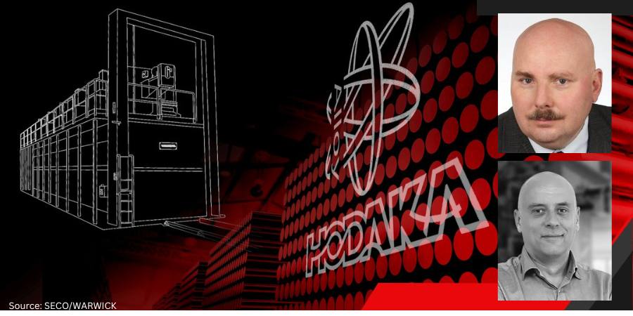
Taiwan Hodaka Technology, an aerospace and automotive manufacturer, extends its market reach by adding an aluminum aging furnace to its heat treatment capabilities. The furnace, which is designed for aging using T77 technology, will allow the company to meet the highest safety and strength standards.
This is the first transaction between Taiwan Hodaka Technology, which is involved in the design and processing of parts made of aluminum alloys, and SECO/WARWICK. The furnace operates in the temperature range from 176° to 428°F (80° to 220°C) with a temperature uniformity in the last heating phase, of ±47.4°F (3°C) in accordance with the AMS 2750 standard.
“The solution supplied by SECO/WARWICK will allow us to enter a new market segment. We are a partner for many key players in the aviation industry. The T77 aluminum aging furnace will enable us to serve customer requirements even better. At the same time, the new technology will support our commitment to reducing our impact on the environment,” said Dr. Sam Chiang, vice president for R&D at Taiwan Hodaka Technology Co. Ltd.
Tomasz Kaczmarczyk, Sales Manager of the Aluminum Process and CAB Furnaces Teams, SECO/WARWICK
For heat treated alloys (2xxx, 6xxx and 7xxx series), the letter T and one or more digits are used after the alloy series symbol. The first digit is the most important, as it indicates the type of heat treatment applied to the alloy, while the remaining digits (if provided) indicate heat treatment variants or their modifications. The 7000 series of aluminum alloys have the highest strength of all other aluminum alloy series and are commonly used in aviation since they are held to the highest safety and strength standards.
“T7 denotes the process of solution heat treatment and artificial aging to an overaged state to obtain specific properties, e.g. increased corrosion resistance,” said Tomasz Kaczmarczyk, sales manager of the Aluminum Process and CAB Furnaces Team at SECO/WARWICK. “Sometimes, in addition to the digit denoting the standard heat treatment, an additional digit is used to denote modifications to the given treatment or stress relief procedures. For example, for 7xxx alloys, the symbol T77 denotes retrogression and re-aging. The use of this process improves the alloy’s corrosion resistance, which is so crucial in the production of aircraft parts. The applied technology will allow Taiwan Hodaka Technology to produce high-quality profiles used in the aviation industry in accordance with the AMS standard.”
Piotr Skarbiński Vice President of Aluminum and CAB Products Segment SECO/WARWICK
“The furnace on order equipped with electric heating will process 1500 kg of aluminum profiles with a maximum length of 5500 mm. This is a two-zone solution with a total heating power of 420 kW. The solution for aluminum aging, powered by electric heaters, eliminates the problem of CO2 emissions and is in line with the ecological trend increasingly common in heavy industry,” said Piotr Skarbiński, vice president of the CAB and aluminum products segment at SECO/WARWICK.
The furnace will be used at the company’s newly built plant in Taiwan.
The project partner was PEERENERGY, which offers thermal process consulting, project management, and equipment supply for the aerospace, military equipment, and semiconductor industries.
The press release is available in its original form here.
We’re celebrating getting to the “fringe” of the weekend with a Heat Treat Fringe Friday covering news about a Class A safety batch furnace delivered to a supplier to the medical industry. The components manufacturer needed equipment that would accommodate the doorway dimensions of its facility and found a Pennsylvania-based international industrial and laboratory furnace manufacturer able to design one to fit the specs.
While not exactly heat treat, “Fringe Friday” deals with interesting developments in one of our key markets: aerospace, automotive, medical, energy, or general manufacturing.
A supplier to the medical industry recently purchased a Class A safety oven from an international industrial and laboratory furnace manufacturer. The Pennsylvania-based provider designed the batch furnace for ease of move-in and installation, modified to an overall height of 79 inches and width of 45” to accommodate the ceiling height and doorway dimensions at the client’s facility.
Blue M® manufactured the furnace with a temperature range of 15°C (59°F) above ambient to 316°C (601°F). The temperature is controlled by a Watlow EZ Zone PM controller with advanced PID control algorithm. The controller offers TRU-TUNE™ adaptive control for tight control and auto-tune for a quick, efficient start up.
“Blue M offers customers the flexibility to request engineered-to-order modifications to our standard oven designs,” said Jonathan Young, product manager at Blue M. “This Class A oven features custom exterior dimensions to accommodate the customer’s facility ceiling height and doorways. This is the second unit with these special dimensions that this customer has ordered.”
The interior chamber has dimensions of a 48″ W x 24″ D x 48″ and is constructed with 304 stainless steel. All of the seams and ports of the interior chamber are Heli-Arc welded vapor tight to prevent fume infiltration and buildup of flammable materials between the chamber walls. The unit includes five (5) 304 stainless steel slotted shelves with rolled fronts for ease of product loading. Each shelf is capable of holding a 75lb product load.
Blue M is located in New Columbia, PA, owned by Thermal Product Solutions.
The press release is available in its original form here.
Many heat treat processes require protective or process gases. These gases often require careful monitoring. One of the protective and/or process gases used in many heat treat applications is an endothermic atmosphere which is made up largely of CO, CO2, H2, and N2. This article is about the creation and proper monitoring of endothermic atmospheres.
In an atmosphere furnace, the proper mix of these gases can help facilitate changes in the metal such as proper hardness and strength, resistance to temperature, or improved tensile strength to mention a few. Without careful control of temperature, time and atmosphere, metals can experience unwanted changes in properties such as hydrogen embrittlement, surface bluing, soot formation, oxidation, and decarburization. With such critical outcomes in the balance, it is necessary to control the endothermic gas.
An excerpt:
“In order for the required metal treatment to be a success, you must control and monitor the gas composition with extreme care. The concentrations of gases, CO₂, H₂O, CH₄, N₂, H₂ and CO, that make up the endothermic gas atmosphere should be measured in order to aid the prevention of unwanted reactions and ensure that the endogas generator and the furnace are operating normally.”
During the day-to-day operation of heat treat departments, many habits are formed and procedures followed that sometimes are done simply because that’s the way they’ve always been done. One of the great benefits of having a community of heat treaters is to challenge those habits and look at new ways of doing things. Heat TreatToday‘s 101 Heat TreatTips, tips and tricks that come from some of the industry’s foremost experts, were initially published in the FNA 2018 Special Print Edition, as a way to make the benefits of that community available to as many people as possible. This special edition is available in a digital format here.
Today, we begin an intermittent series of Technical Tuesday posts of the 101 tips by category, starting with Atmosphere Control.
Atmosphere Control
Heat TreatTip 5
Out of Control Carburizing? Try This 11-Step Test
When your carburizing atmosphere cannot be controlled, perform this test:
Empty the furnace of all work.
Heat to 1700°F (926°C).
Allow endo gas to continue.
Disable the CP setpoint control loop.
Set generator DP to +35°F (1.7°C).
Run a shim test.
The CP should settle out near 0.4% CP.
If CP settles out substantially lower and the CO2 and DP higher, there’s an oxidation leak, either air, water or CO2 from a leaking radiant tube.
If the leak is small the CP loop will compensate, resulting in more enriching gas usage than normal.
Sometimes but not always a leaking radiant tube can be found by isolating each tube.
To try and find a leaking radiant tube, not only the gas must be shut off but combustion air as well.
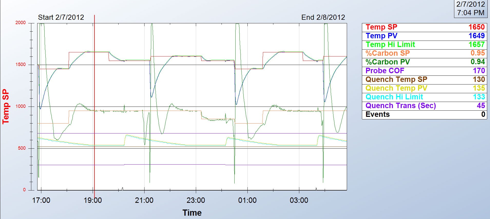
So you just ran a batch and the parts are bad. Now what? According to Jim Oakes at Super Systems Inc., here is a good checklist to use to start isolating the problem. While not exhaustive, this list can at least take you through a progression of steps to help start identifying the culprit.
Step 1: Review the process data for abnormalities. Did the setpoint for temperature and atmosphere get set properly? Does the process chart show good control of the temperature and atmosphere? Was the time at heat correct? Was the quench and temper processes run properly?
Step 2: Check the generator to make sure it was pumping out the right atmosphere.
Step 3: Check the furnace atmosphere. Even if the generator is working, there may be leaks in the furnace.
Step 4: Check carbon controller to make sure it matches furnace atmosphere reading. Verify probe accuracy and adjust carbon controller.
Step 5: Do probe troubleshooting. And if all else fails . . .
Step 6: Replace the probe or call Super Systems for help.
Many factors can contribute to why parts are not meeting the correct hardness readings. According to Super Systems Inc., here is a quick checklist of how to start narrowing down the culprit:
Review process data for abnormalities: The first thing to do is make sure the parts were exposed to the right recipe. Check the recorders to make sure the temperature profile and atmosphere composition were correct. Make sure all fans and baffles were working correctly. Determine if any zones were out of scope and that quench times were acceptable. If any red flags appear, hunt down the culprit to see if it may have contributed to soft parts.
Check the generator. Next, check the generator to make sure it is producing the gas composition desired for the process. If available, check the recorders to make sure the gas composition was on target. If not, check the generator inputs and then the internal workings of the generator.
Check the furnace atmosphere. If the generator appears to be working correctly, the next step would be to check the furnace itself for atmosphere leaks. Depending on what type of furnace you have, common leak points will vary; for continuous furnaces, common leak points are a door, fan, T/C, or atmosphere inlet seals. Other sources of atmosphere contamination may be leaking water cooling lines in water-cooled jackets or water-cooled bearings. More than likely, if the generator is providing the correct atmosphere but parts are still soft, there is a leak into the furnace. This will often be accompanied by discolored parts.
Check carbon controller to make sure it matches furnace atmosphere reading (verify probe accuracy and adjust carbon controller). This can be done using a number of different methods: dew point, shim stock, carbon bar, 3 gas analysis, coil (resistance), etc. Each of these methods provides a verification of the furnace atmosphere which can be compared to the reading on the carbon controller. If the atmosphere on the carbon controller is higher than the reading on the alternate atmosphere check, that would indicate the amount of carbon available to the parts is not as perceived. The COF/PF on the carbon controller should be modified to adjust the carbon controller reading to the appropriate carbon atmosphere. If the reading is way off, it may require the probe to be replaced.
Configuring your atmosphere controller to ensure the correct carbon potential readings can sometimes be tricky. We suggest you double check your atmosphere control settings to make sure they are set up correctly. Before making a change to the carbon controller, make sure the atmosphere that the carbon probe and carbon controller are reading is matching up to an alternate method of atmosphere. This can be done using a number of different methods: dew point, shim stock, carbon bar, 3 gas analysis, coil (resistance), etc. Each of these methods provides a verification of the furnace atmosphere which can be compared to the reading on the carbon controller. The COF/PF on the carbon controller should be modified to adjust the carbon controller reading to the appropriate carbon atmosphere.
It is important to make sure that the alternate method of verifying atmosphere is done properly (sampling ports, time for atmosphere exposure, sample prep, etc).
The calculation of carbon in the atmosphere using a carbon/oxygen probe is based on the output millivolts — created based on the partial pressure of oxygen in the reference air versus partial pressure of oxygen in the furnace, the temperature of the furnace, and a calculation factor referred to as COF (CO Factor), PF (Process Factor), or Gas Factor.
The carbon controller can be modified so the COF/PF value can be changed to match up with the alternate reading. A furnace calculator on the SSI website or mobile app can help determine what these settings should be. It is important to note that you should not change these values to the point where you are masking another issue such as a bad probe or a furnace/generator issue.
Again, if the reading is way off (a setting of a COF below 130, for example), it may require the probe to be replaced.
If you’re having atmosphere problems with a furnace that has been operating normally for some time, avoid the temptation to remove the carbon probe. There are several tests you can run on nearly all carbon probes while the probe is still in the furnace, at temperature, in a reducing atmosphere. Super Systems Inc. provides an 11-step diagnostic procedure in a white paper on their website, in a paper titled, “Carbon Sensor Troubleshooting” by Stephen Thompson.
Atmosphere furnace pressure should be only slightly above ambient. The range should be between 0.25 – 0.35 inches water column. Higher pressures in multiple zone pusher furnaces will cause carbon control issues. High pressures in batch furnaces will cause high swings when doors and elevators move.
Wisdom dictates a trust-but-verify approach to your endothermic generator. Although your generator is supposed to crank out a consistent endo atmosphere, we suggest periodically verifying the integrity of that atmosphere with a dewpoint analyzer or a 3-gas analyzer. Generator control systems provide control of air gas ratio and possibly a trim system, used to maintain a dew point that could be rich (too much gas) or lean (too much air). The dew point range could typically be between 30°F and 50°F. Flowmeters are provided to maintain a base ratio (2.7 : 1) for the air/gas mixture supplied to a retort filled with nickel-coated catalyst. The gas is then passed through an air cooler (some older systems used water) to freeze the reaction so the gas can be transported through a header system to furnaces. The ratio at which the gas is generated offers a dew point that can be measured. The makeup of the endothermic gas provided by a generator is typically 40% hydrogen, 40% nitrogen, and 20% carbon monoxide. Maintaining these percentages will result in a carburizing atmosphere that is conducive to best carburizing practices.
Non-dispersive infrared analyzer (NDIR) systems are invaluable when trying to troubleshoot generator issues. The analyzer will typically measure CO, CO2, and CH4. As mentioned earlier, if we know that 20% CO is being generated, we can cross check the air/gas ratio and sticking flow meters, or determine that an adjustment of the air and/or gas ratio is required. The measurement for indication of sooted or nickel depleted catalyst can also be achieved by using an analyzer. If the indicated measurement of CH4 is higher than .5%, a burnout of the catalyst is required, using the manufacturer’s required procedures. If after a burnout the CH4 level is still high, the catalyst may need to be replaced altogether.
If you have any questions, feel free to contact the expert who submitted the Tip or contact Heat TreatToday directly. If you have a heat treat tip that you’d like to share, please send to the editor, and we’ll put it in the queue for our next Heat TreatTips issue.