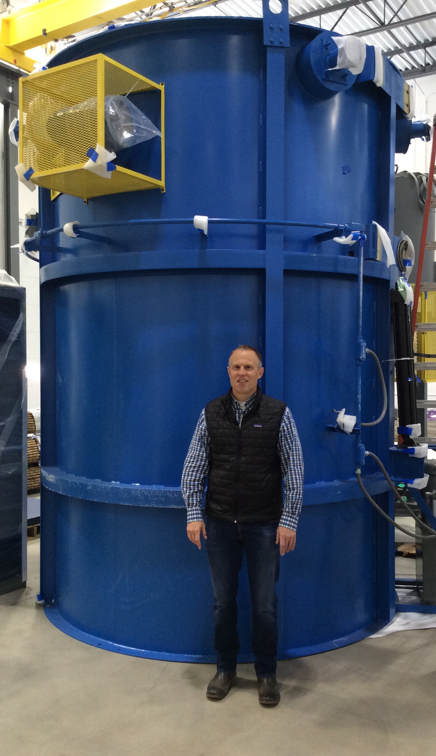
A heat treating services and metallurgical solutions company recently announced the arrival of three new gas nitride units at its corporate headquarters, doubling the gas nitriding capacity at this location and allowing the company to expand its UltraGlow® gas nitriding and UltraOx® surface treatment solutions.
The three new gas nitride units at Advanced Heat Treat Corp’s Waterloo, Iowa, corporate facility vary in size, allowing for the accommodation of various industries and applications including, but not limited to: aerospace, automotive, oil and energy, agriculture, construction, and firearms.
AHT President Mikel Woods with new gas nitriding unit.
One nitride unit will be operational this month, and the additional two units will be running in February. AHT also has plans to design and build an additional unit later in 2019.
“I’m excited on many accounts,” said AHT President, Mikel Woods. “One, we’re adding capacity/back-up to an already growing agriculture/construction market. Two, we have plans to add a new Nadcap process in order to expand further into the aerospace market and meet our customer requirements/requests. And three, we’re gearing up to go even bigger in 2019 with additional equipment.”
The new units will house AHT’s UltraGlow Gas Nitriding and UltraOx services, commonly used in manufacturing to prevent corrosion and improve wear resistance.
“UltraOx is rapidly replacing processes like QPQ/salt bath, chrome plating, and nickel plating; therefore, it was pivotal for us to invest in more equipment so that we can accommodate the growing demand and continue to provide our customers with the quality and service they have come to expect from AHT,” said Woods.
AHT is currently Nadcap accredited for ion nitriding at their corporate location, but with the additional capacity, AHT plans to gain accreditation in gas nitriding by this summer as well. The additional Nadcap accreditation will help AHT to accommodate additional aerospace needs and grow their UltraGlow gas nitriding service.
Photo caption (main): John Ludeman, AHT Quality and Continuous Improvement Manager; Dan Sager, Assistant Operations Manager; Jill Manning, AHT accountant; Carlos Urzagaste, AHT maintenance supervisor
Induction Hardening Tips: Equipment Selection for Scan Hardening, Part 3
This is the third installment of a multi-part column on equipment selection for induction heat treatment. Part 1, Dr. Valery Rudnev On . . . Induction Hardening Tips: Equipment Selection for Scan Hardening, covered types of scanners, scan hardening system setup, quenching challenges, maximizing process flexibility, and computer modeling. In Part 2, Dr. Valery Rudnev discussed another critical aspect of induction scan hardening: inductor design subtleties and a comparison of different fabrication techniques (brazing vs. CNC
machining vs. 3D printing).
In this installation, Dr. Rudnev focuses on Moveable Inductor versus Moveable Part.
Moveable Inductor versus Moveable Part
As stated in one of the previous installments of this column, when a scan processing mode is chosen, either the inductor or the part or both may be moved during the heating and quenching. This installment discusses the applicability of those approaches (movable inductor vs. movable part), as well as pros and cons associated with both techniques.
Figure 1. An example of scan hardening of track shoes for earth-moving machines that often specify deep hardness case depths (up to the 24 mm).
The choice to move the inductor or to move the part is primarily based on required production rate as well as on the size, weight, and geometry of the component compared to the size, weight, and geometry of the inductor: in other words, it depends on which of the two is easier to move.
Weight is an important factor because the movement can occur several hundred times each day and, in some cases of high production, even several thousand times per day. For example, during induction surface hardening of track shoes for earth-moving machines that often specify deep hardness case depths (up to 24 mm), it is much easier to move the inductor around the workpiece instead of moving the track shoes, the weight of which can exceed several thousand pounds. (Figure 1)
When moving the inductor, both flexible cables and hoses are used or the inductor is hard-bused to the transformer and the transformer or heat station moves with the inductor. In some cases, the power supply itself may be moved at a moderate rate to scan a stationary workpiece [1]. Another example of moving the inductor is surface hardening of trailer axles. (Figure 2)
Figure 2. (Left image) Horizontal scanner to induction harden both ends of a trailer axle. A walking beam system was incorporated into the machine for part transfer. At the heating station, the axle is lifted off the beam and the power supply and inductor are indexed to position for scan hardening. After the completion of surface hardening of one end, the axle is then lifted off the transfer mechanism and rotated 180° to induction harden the opposite end. Heavy-duty precision shafting and bearings are used for stability and consistency. (Right image) shows a close-up of a movable inductor to scan harden trailer axle ends. Heating time is less than 8 s per axle end.
The length of the part to be heated is also an important consideration When a component is of moderate weight, it is obviously preferable to move the part rather than the inductor. For example, it is much easier and more cost-effective to design a hardening system that anticipates moving a workpiece that weighs less than 0.25 kg (<0.5 lb) rather than moving an entire power supply, as it is shown in Figure 3.
Figure 3. Horizontal scanner that provides a maximum scan rate up to 200 mm/s (8 in./s). (Courtesy of Inductoheat Inc., an Inductotherm Group company.)
In other cases, it may not be practical to move very large and elongated components. It would consume too much floor space to move the part through a stationary inductor. In the case of low production rates, the best choice might be to move the inductor, but the length of the high-frequency power leads could become a problem with respect to voltage drop and power loss. In this case, it is preferable to move the inductor with the power supply attached. Then, the moving cables are operating at a low frequency (50–60 Hz) with lower voltage drop and power loss. In the case of high production, continuous horizontal systems may be more suitable.
The consideration of the length of the leads (e.g., cables or buses) from the power source to the inductor is important. They should be as short as possible to conserve energy and to allow the power source to operate properly without reaching any limits (for example, voltage limit). If these leads are too long, the inductance increase can be so significant that it may result in a substantial power loss and voltage drop. The voltage drop in the leads may even exceed the voltage at inductor’s terminals. Long leads could net an excessive total needed power, a measurable reduction in energy efficiency, and potential concerns regarding the process repeatability owing to the possibility of an appreciable inductance change of the flexible leads during their motion, that in some cases may negatively impact process repeatability.
Whether moving the inductor or moving the part, the induction system can be designed to be efficient and robust in order to ensure smooth and consistent operation and the production of quality parts.
I recommend Reference #1 to readers interested in further reading on this subject.
References
V. Rudnev, D. Loveless, R. Cook, Handbook of Induction Heating, 2nd Edition, CRC Press, 2017.
Dr. Valery Rudnev, FASM, IFHTSE Fellow, is the Director of Science & Technology, Inductoheat Inc., and a co-author of Handbook of Induction Heating (2nd ed.), along with Don Loveless and Raymond L. Cook. The Handbook of Induction Heating, 2nd ed., is published by CRC Press. For more information click here.
A thermal processing equipment manufacturer based in Maumee, Ohio, recently supplied a batch integral quench furnace for a metal treating company in Raleigh, North Carolina, that services the automotive, aerospace and defense sectors, as well as general manufacturing.
East Carolina Metal Treating’s (ECMT) purchase of the Allcase® Batch Integral Quench Furnace from Surface® Combustion Inc. is a repeat order. Identical to the previously commissioned Allcase furnace, the new equipment is configured to process 36” wide by 48” long by 36” high workloads that weigh up to 4,000 lbs. In addition, Surface has supplied two air cool stations, a scissors lift table, and two stationary load tables that integrate with an existing IQ line.
The new Allcase works seamlessly with ECMT’s existing charge car, tempers, and washer, following the incorporation of a purchaser specified controls system to match the existing UPC controls on the initial order, and features a Vertical Radiant Tube Heating System with direct spark ignition and flame monitoring, recuperated burners and plunge cooling. A maintenance platform with access stairs allows for fast and easy maintenance. An integrated Top Cool Chamber was provided to further expand process applications, a hallmark of the Allcase furnace which was invented for the greatest range of thermal processing; all case-hardening and non-case hardening applications under controlled atmospheres.
“As always our team did a great job but a special shout out to the Surface Combustion and UPC Teams involved in this project. This was our first project with Surface and their reputation holds true as expected,” said Jamie Ramm, president of ECMT.
Heat TreatToday Technical Tuesday contributor, Dr. Valery Rudnev, FASM, IFHTSE Fellow, “Professor Induction”, and Director of Science and Technology at Inductoheat, Inc, is the featured speaker of an ASM International Materials Solutions webinar titled “Simple Solutions for Common Induction Heating Challenges: Lessons Learned”.
Dr. Rudnev will present this webinar on Thursday, January 24, 2019, 2 pm, and address:
Induction hardening of powertrain transmission and engine components
Failure analysis
How to avoid cracking in induction hardening
Subtleties of heating parts with holes, fillets, and other geometrical irregularities
Re-hardening (re-austenitization) of previously hardened parts
Novel inverters that allow instant and independent adjustment of both frequency and power
Selected challenges when applying induction tempering
Reducing process sensitivity and improving robustness and flexibility of induction systems.
Note: Attendees will earn a professional development hour for attending the webinar.
This webinar is sponsored by Inductoheat, Inc. For more information and to register, click here.
Heat TreatToday offers News Chatter, a feature highlighting representative moves, transactions, and kudos from around the industry.
Personnel and Company Chatter
Julien Noel has been named Vice President / General Manager of the Buehler worldwide division. ITW Test and Measurement Group President, Yahya Gharagozlou, made the announcement. Buehler is an ITW Company which manufactures scientific equipment and consumables for materials analysis.
A fourth vacuum aluminum brazing (VAB) furnace has been purchased by California Brazing, a Newark, California, heat treating company in order to expand the capability to service the aerospace sector.
Solar Atmospheres recently awarded the title of CEO Emeritus to Roger A. Jones, FASM. The honorary title was conferred by the company and announces his semi-retirement as Solar Atmospheres’ CEO, the culmination of 45 years of leadership and service to the vacuum heat treating industry.
A refractories supplier’s recently established partnership will result in the full-service distribution of the company’s products and services throughout several European countries. The Plibrico Company and Pli Group Europe GmbH, a highly experienced refractory distributor contractor based in Vienna, Austria, have entered into a new value-added distribution partnership will cover Austria, France, Germany, Switzerland, Italy, Hungary, Czech Republic, Slovakia, Slovenia, Croatia, Serbia, and Bulgaria.
The world’s largest aerospace company, the Boeing Company recently acquired Embraer SA, the commercial aircraft arm of a Brazilian aircraft manufacturer, in a new $4.75 billion joint venture.
Equipment Chatter
Seven Gruenberg Glassware drying ovens were recently shipped to a university in the U.S. Midwest by Thermal Product Solutions, a manufacturer of thermal-processing equipment based in New Columbia, Pennsylvania.
A furnace equipment company based in Erie, Pennsylvania, recently designed and manufactured a front-loading forge furnace for a leading North American forging company. The furnace built by Onex, Inc., is one of the largest of its kind in North America with workspace dimensions measuring 26ft (W) x 20ft (D) x 14ft (H).
A heat treating services provider in the U.S. Northwest recently purchased a Meg-HIP hot isostatic press for heat treating and metal processing. Västerås, Sweden-based, Quintus Technologies installed the system at Stack Metallurgical Group in Albany, Oregon.
Kudos Chatter
Thermal-Vac Technology, Inc. has been awarded a 2018 Top Workplaces honor by The Orange County Register. The list is based solely on employee feedback gathered through a third-party survey administered by research partner. The anonymous survey measures several aspects of workplace culture, including alignment, execution, and connection, just to name a few.
AK Steel recently announced that it has accepted an award of up to $1.2 million from U.S. Department of Energy (DOE) under the Office of Energy Efficiency and Renewable Energy’s (EERE) Advanced Manufacturing Office program to investigate novel low-density steels in the laboratory, which could ultimately be used in automotive structural applications. The three-year project will be conducted in collaboration with DOE, Oak Ridge National Laboratory Materials Science and Technology Division, and the Advanced Steel Processing and Products Research Center in the Department of Metallurgical & Materials Engineering at the Colorado School of Mines. The objective of the project is to conduct alloy design, laboratory validation, and testing of low-density steels that are alternatives to currently available advanced high strength steels and other lightweight metals.
Heat Treat Today is pleased to join in the announcements of growth and achievement throughout the industry by highlighting them here on our News Chatter page. Please send any information you feel may be of interest to manufacturers with in-house heat treat departments especially in the aerospace, automotive, medical, and energy sectors to the editor at editor@heattreattoday.com.
Open any garage today and the vehicle you’ll find inside is likely to contain components achieved by lightweighting methods. In fact, it’s a practice that goes back to the days of removing backseats from the cars we inherited from older siblings because the drive for speed and basic economics together has always propelled designers, engineers, and backyard gearheads to find a way to produce a lighter vehicle.
Industry Week recently took a look at the technology and materials that mark the road to development of today’s parts made from ultra-high-strength blends of steel, aluminum, magnesium, and carbon fiber, relying on next-gen design software and techniques such as additive manufacturing and resulting in lighter and stronger vehicles and vehicle components.
Gregory E. Peterson, principal materials engineer for the Michigan Manufacturing Technology Center, a consulting organization that helps manufacturers improve profits and performance, “points to the lightweighting rule that a 10% weight reduction leads to a 6% to 7% increase in fuel economy.”
The Michigan Manufacturing Technology Center helped develop an aftermarket Corvette (C2) frame that is lighter and stronger than the original.
Carmakers are responding with forwarding thinking business changes that include workforce, design, and footprint. For example, GM is focusing on electric or fuel-cell powered vehicles, which will require a paradigm shift in part production — in just about every aspect of its current manufacturing protocol. How does this look on the ground, in the lab, where the decisions are matter?
Why does a seat belt bracket look the way it does? Because of machining requirements. But what if machining was replaced by additive manufacturing?
“You unhinge yourself from those constraints with generative design. It opens up a whole new set of lightweighting opportunities that we have based on designs we can’t make any other way,” said Kevin Quinn, GM Director of Additive Design and Manufacturing.
Photo credit and caption: The Michigan Manufacturing Technology Center helped develop an aftermarket Corvette (C2) frame that is lighter and stronger than the original.
During the day-to-day operation of heat treat departments, many habits are formed and procedures followed that sometimes are done simply because that’s the way they’ve always been done. One of the great benefits of having a community of heat treaters is to challenge those habits and look at new ways of doing things. Heat TreatToday‘s 101 Heat TreatTips, tips and tricks that come from some of the industry’s foremost experts, were initially published in the FNA 2018 Special Print Edition, as a way to make the benefits of that community available to as many people as possible. This special edition is available in a digital format here.
Today we offer one of the 101 tips, which was provided by AeroSPC and originally published under Miscellaneous Tips.
Heat TreatTip #42
Burn Out vs. Bake Out: What’s the Diff?
Many organizations use the term burn out and bake out to be the same event. Others have burn out understood to be 50°F above prior maximum temperature after the braze process for a short period. Bake out then is a “close to max” temperature of the oven maintained for over an hour. If your organization is using these terms, ensure that they are internally defined and in alignment with the terms used in your customer specifications.
If you have any questions, feel free to contact the expert who submitted the Tip or contact Heat TreatTodaydirectly. If you have a heat treat tip that you’d like to share, please send to the editor, and we’ll put it in the queue for our next Heat TreatTipsissue.
A North American steel and steel products manufacturer recently announced plans to build a state-of-the-art plate mill with heat treating included in its range of processing.
Leon Topalian, Nucor’s Executive Vice President of Beam and Plate products
Nucor Corporation, based in Charlotte, North Carolina, will invest $1.35 billion to build the mill, which will be based in the U.S. Midwest and produce cut-to-length, coiled, heat-treated, and discrete plate ranging from 60 to 160 inches wide, and in gauges from 3/16 of an inch to 14 inches in thickness, enabling Nucor to supply plate products that the Company does not currently offer.
“By building this state-of-the-art plate mill in the Midwest – the largest plate-consuming area in the United States – we will enhance our ability to serve our customers in the region while also furthering our goal of meeting all the steel needs of our customers around the country,” said Leon Topalian, Nucor’s Executive Vice President of Beam and Plate products. “We expect to select a site for the new mill early this year. Our team is poised and ready to take the next step in advancing our position in steel plate products.”
Nucor’s Board of Directors has approved an investment of $1.35 billion to build the mill, which is expected to be fully operational in 2022 and will be capable of producing 1.2 million tons per year of steel plate products.
John Ferriola, Chairman, CEO & President of Nucor
“This investment is consistent with our drive to continue delivering sustainable, profitable growth and superior returns for shareholders,” said John Ferriola, Chairman, CEO & President of Nucor. “Together with the significant share repurchases completed in 2018, the Board’s decision to fund this high-return opportunity demonstrates our commitment to balanced capital allocation. We have a strong foundation to build upon as we advance our goal of leading in every market in which we compete.”
Nucor currently operates plate mills in North Carolina, Alabama, and Texas.
This is the first in a 4-part series by Dr. Steve Offley (“Dr. O”), Product Marketing Manager at PhoenixTM, on the technical challenges of monitoring low-pressure carburizing (LPC) furnaces. This introductory article explains the LPC process and general monitoring needs and challenges.
Carburizing Process
Dr. Steve Offley (“Dr. O”), Product Marketing Manager PhoenixTM
Carburizing has rapidly become one of the most critical heat treatment processes employed in the manufacture of automotive components. Also referred to as case hardening, it provides necessary surface resistance to wear while maintaining toughness and core strength essential for hardworking automotive parts.
The carburizing heat treatment process is commonly applied to low carbon steel parts after machining, as well as high alloy steel bearings, gears, and other components. Being critical to product performance, monitoring and controlling the product temperature in the heat treatment process is essential.
The carburizing process is achieved by heat treating the product in a carbon-rich environment, typically at a temperature of 900 – 1050 °C / 1652 – 1922 °F. The temperature and process time significantly influences the depth of carbon diffusion and associated surface characteristics. It is critical to the process that, following diffusion, a rapid quenching of the product is performed in which the temperature is rapidly decreased. This generates the microstructure giving the enhanced surface hardness while maintaining a soft and tough product core.
Increasing in popularity in the carburizing market is the use of batch or semi-continuous batch low-pressure carburizing furnaces. New furnace technology employs the dissociation of acetylene (or propane) to produce carbon in an oxygen-free low-pressure vacuum environment, which diffuses to a controlled depth in the steel surface. Following the diffusion, the product is transferred to a high-pressure gas quench chamber where it is rapidly gas cooled using typical N2 or Helium up to 20 bar.
An alternative to gas quenching is the use of an oil quench, used commonly in continuous carburizing furnaces where the products are plunged into an oil bath.
Fig 1: Schematics of the LPC Carburizing process showing the Temperature and Pressure steps
Temperature Monitoring Challenges in Low-Pressure Carburizing
As already stated, the success of the carburizing process is governed by careful control of both the process temperature and duration in the heating and quench stages. Obviously, when considering temperature, we are interested in the product temperature, not the furnace. Measuring product temperature through a carburizing process, although possible using trailing thermocouples, as performed historically, is neither easy nor safe, and it disrupts production for lengthy periods.
PhoenixTM provides a superior solution with the use of a “thru-process” temperature monitoring system. As the name suggests, the PhoenixTM temperature profiling system is designed to travel through the thermal process, measuring the product and or furnace environment from start to finish. The system can be incorporated into a standard production run so does not compromise productivity. A high accuracy, multi-channel data logger records temperature from thermocouple inputs, located at points of interest on, in, or around the product being thermally treated. To protect the data logger as it travels through the hostile furnace, a thermal barrier is employed to keep the logger at a safe working temperature to prevent damage and ensure accuracy of measurement. The barrier also obviously needs to protect during the quench, whether that be against high pressure or oil ingress if the quench can’t be avoided.
Employing the PhoenixTM system a complete thermal record of the product throughout the entire process can be collected. A popular enhancement to the system is the use of 2-way RF telemetry, providing real-time process monitoring directly from the furnace, useful for either profiling or performing a live Temperature Uniformity Survey (TUS). The product temperature can be viewed live and downloaded at any point in the furnace. Raw temperature data collected from the process can be converted into useful information using one of the custom-designed PhoenixTM Thermal View Software packages available. The thermal graph can be reviewed and analyzed to give a traceable, certified record of the process performance. Such information is critical to satisfying CQI-9, AMS2750, and other regulatory demands. Fully TUS-compliant reports can be produced in moments from the simple and intuitive software, making accurate TUS a simple and quick task. Information can be used to not only prove product quality but provide the means to confidently change process characteristics to improve productivity and process efficiency (Optimize Diffusion, Soak and Quench).
The world’s largest first-tier aerostructures manufacturer recently announced that the company plans to expand operations at its Tulsa, Oklahoma, site by investing more than $80 million in capital projects to support fuselage manufacturing and assembly work.
Spirit AeroSystems, Inc., based in Wichita, Kansas, will be hiring about 250 employees as part of this expansion. The new Tulsa project will support increases in 737 production rates by freeing up required space in Spirit’s Wichita factory site. The work expansion in Tulsa is part of a larger effort to maximize operational efficiencies across Spirit’s sites. As the production rates increase, the Wichita site will continue to hire additional workers to meet the increasing demand.
Spirit AeroSystems President and CEO Tom Gentile
The first phase of the Tulsa work expansion will begin with infrastructure set-up and employee training beginning in 2019. Full rate production is expected to be complete by the end of 2021. Additional investment in equipment, tooling and facilities upgrades will take place through 2022.
“This expansion would not have been possible without the strong collaboration among Spirit, the UAW, and Oklahoma state and local officials,” said Spirit AeroSystems President and CEO Tom Gentile. “The Spirit team in Tulsa has made great strides in improving the site’s efficiency and demonstrating the capability to bring in additional work. The Tulsa site has a critical role in helping Spirit meet rising airplane production rates and pursue growth opportunities.”
In addition, Spirit announced that it executed a Memorandum of Agreement (MOA) with The Boeing Company, extending its partnership with the aerospace giant and leading manufacturer of airplanes, rotorcraft, rockets, satellites, and missiles worldwide. Spirit builds several important pieces of Boeing aircraft, including the fuselage of the 737, portions of the 787 fuselage, and the cockpit section of the fuselage of nearly all of its airliners.
“This agreement further strengthens the long-standing partnership between Boeing and Spirit as it removes uncertainty well into the next decade. The agreement establishes pricing and capital investment for a range of potential production rate increases on the 737 program. With the new agreement, we expect price to exceed cost eventually on the 787 program. We are excited to continue to build on our relationship and look forward to future opportunities with our largest customer,” said Gentile. “With this agreement, we maintain our target of 7 to 9 percent conversion of revenue to free cash flow.”
Photo caption: Spirit AeroSystems president and CEO Tom Gentile announces Tulsa expansion (Twitter).